SICK Flexi Soft Operating Instructions Manual
Hide thumbs
Also See for Flexi Soft:
- Operating instructions manual (196 pages) ,
- Operating instructions manual (200 pages)
Table of Contents
Advertisement
Advertisement
Table of Contents
Troubleshooting

Related Manuals for SICK Flexi Soft


Summary of Contents for SICK Flexi Soft
- Page 1 O P E R A T I N G I N S T R U C T I O N S Flexi Soft Gateways...
- Page 2 This document is protected by the law of copyright, whereby all rights established therein remain with the com- pany SICK AG. Reproduction of this document or parts of this document is only permissible within the limits of the legal determination of Copyright Law. Alteration or abridgement of the document is not permitted without the explicit written approval of the company SICK AG.
-
Page 3: Table Of Contents
Configuration of the gateways............29 4.3.3 Transfer of a configuration ...............30 4.3.4 Verification of a configuration ............30 4.3.5 Upload of a configuration ..............31 8012664/XB29/2013-06-11 © SICK AG • Industrial Safety Systems • Germany • All rights reserved Subject to change without notice... - Page 4 Ethernet over EtherCAT (EoE) ............110 5.5.8 TCP/IP configuration interface............110 5.5.9 CoE (CAN application layer over EtherCAT) ........111 5.5.10 Diagnostics and troubleshooting ...........114 © SICK AG • Industrial Safety Systems • Germany • All rights reserved 8012664/XB29/2013-06-11 Subject to change without notice...
- Page 5 7.3.7 Saving and loading a configuration..........181 7.3.8 Importing and exporting a configuration........181 Monitoring the operational data online ............182 8012664/XB29/2013-06-11 © SICK AG • Industrial Safety Systems • Germany • All rights reserved Subject to change without notice...
- Page 6 Dimensional drawing FX0-GPRO, FX0-GCAN and FX0-GDEV ..188 Ordering information Flexi Soft gateways ............188 Annex..........................189 EC declaration of conformity................189 List of tables .....................191 List of illustrations ....................195 © SICK AG • Industrial Safety Systems • Germany • All rights reserved 8012664/XB29/2013-06-11 Subject to change without notice...
-
Page 7: About This Document
Flexi Soft modular safety controller is integrated and who want to exchange data with a fieldbus (a controller) via a gateway. They are also addressed to people who are placing a Flexi Soft gateway in operation for the first time or maintaining it. -
Page 8: Information Depth
Warning! Pay attention to the safety notes and safety measures on the Flexi Soft gateways! WARNING We also refer you to our homepage on the Internet at Note www.sick.com... -
Page 9: Symbols Used
Beckhoff Automation GmbH, Germany.” Other product names and company names referenced in this manual are trademarks or registered trademarks of their respective companies. 8012664/XB29/2013-06-11 © SICK AG • Industrial Safety Systems • Germany • All rights reserved Subject to change without notice... -
Page 10: On Safety
Correct use The Flexi Soft gateways can only be operated with a Flexi Soft system. The firmware ver- sion of the connected FX3-CPUx must be at least V1.11.0, the version of the Flexi Soft Designer configuration software must be at least 1.3.0. -
Page 11: Environmental Protection
The operating instructions must be made available to the operator of the machine where a Flexi Soft system is used. The machine operator is to be instructed in the use of the device by qualified safety personnel and must be instructed to read the operating instructions. -
Page 12: Product Description Flexi Soft Gateways
A Flexi Soft gateway can only be operated on a Flexi Soft system. It does not have a dedi- cated voltage supply. It is possible to use two Flexi Soft gateways per system. -
Page 13: Device Variants
The Ethernet gateways FX0-GENT, FX0-GMOD and FX0-GPNT are available with different firmware versions. To add a gateway to a Flexi Soft system in the Flexi Soft Designer’s hardware configuration window, you must select the appropriate step from the drop down list under the respective gateway. -
Page 14: Data Transmitted Into The Network (Input Data Sets)
Data set 1 (max. 50 bytes) contains the operational data. It can be compiled using the Flexi Soft Designer tool. Upon delivery there is a default selection for the content of data set 1 which can be freely modified. For details see Tab. 5 on page 16. - Page 15 CANopen gateway please refer to chapter 6.2 “CANopen gateway” on page 130. 8012664/XB29/2013-06-11 © SICK AG • Industrial Safety Systems • Germany • All rights reserved Subject to change without notice...
- Page 16 Byte 57 Module 13 and 14 are Byte 58 always the gateways. Byte 59 Length 50 bytes 32 bytes 60 bytes © SICK AG • Industrial Safety Systems • Germany • All rights reserved 8012664/XB29/2013-06-11 Subject to change without notice...
-
Page 17: Logic Results
Module status and EFI status as well as input and output values The Flexi Soft gateways can transmit the status and all input and output states of all Flexi Soft modules and EFI devices connected to the Flexi Soft system into the network. Data set 1 containing the input and output values and the EFI information can be customized. - Page 18 (e.g. C4000, S3000). transfer commands to the safety devices. The Flexi Soft gateways allow these EFI devices connected to the FX3-CPU1 or FX3-CPU2 to transmit their data into the network. It is only possible to select the EFI data in byte arrays. 4 byte arrays for each connected EFI Note device are available.
-
Page 19: Routing Of Data From A Second Network
3.3.4 Routing of data from a second network If your Flexi Soft system contains two gateways, it is possible to rout information received by the first gateway from one network (e.g. from a Modbus PLC) into a second network via the second gateway (e.g. - Page 20 Tab. 11: Module status bits of the I/O modules FX0-STIO The module status bits for the FX3-XTIO and FX3-XTDI are fully supported only with firmware version 1.2.x and higher. © SICK AG • Industrial Safety Systems • Germany • All rights reserved 8012664/XB29/2013-06-11 Subject to change without notice...
- Page 21 Tab. 13: Module status bits of the gateways Example Module 2 (Flexi Soft XTIO) has a stuck-at-high error (24 V) on output 3. The following module status will be transferred into the network (only the first 12 of 60 bytes are shown): Tab.
- Page 22 (byte 3, bit 4 in Tab. 9). You will find an example process image in section 5.1.3 “TCP/IP process image example” on page 46. © SICK AG • Industrial Safety Systems • Germany • All rights reserved 8012664/XB29/2013-06-11 Subject to change without notice...
-
Page 23: Data Received From The Network (Network Output Data Sets)
10 bytes The contents of the output data blocks can be used within the FX3-CPUx logic editor and can also be made available to another network via a second Flexi Soft gateway in the Flexi Soft system. In order to make the data from the network available in the logic editor or as input to Notes another network, you must define a tag name for each bit that shall be used. -
Page 24: Mounting And Basic Configuration Of The Gateways
Flexi Soft gateway. 4.1.1 Steps for mounting the modules The Flexi Soft system is only suitable for mounting in a control cabinet with at least IP 54 enclosure rating. WARNING While supply voltage is applied, modules must not be plugged to nor be removed from the Flexi Soft system. - Page 25 Fig. 1: Mounting the module onto the DIN mounting rail Make sure that the voltage supply of the Flexi Soft system is switched off. Hang the device onto the DIN mounting rail ( ). Connect the gateways directly onto the right side of the FX3-CPUx module of the Flexi Soft system.
-
Page 26: Steps For Dismantling The Modules
Press the module downwards at the rear ( ) and remove it from the DIN mounting rail in the direction of the arrow while keeping it pressed down ( ). © SICK AG • Industrial Safety Systems • Germany • All rights reserved 8012664/XB29/2013-06-11... -
Page 27: Electrical Installation
To ensure full electromagnetic compatibility (EMC), the DIN mounting rail must be connected to functional earth (FE). The control cabinet or assembly casing of the Flexi Soft system must comply at least with enclosure rating IP 54. Mounting in accordance with EN 50 274. -
Page 28: Establishing A Connection Between Gateway And Pc
Modify the settings if required and click OK. Click OK. The dialog closes. Click on Connect to physical device. The Flexi Soft Designer will search for connected Flexi Soft devices and load the hardware configuration into the hardware configuration dialog. Once all modules have been identified correctly, the Flexi Soft Designer will ask whether the configuration shall be uploaded. -
Page 29: Configuration Of The Gateways
For the configuration of the operational data (data transfer from and to the network), please refer to chapter 7 “Layout and content of the process image” on page 173. More information can be found in the Flexi Soft Designer operating instructions (SICK part no. 8012998). -
Page 30: Transfer Of A Configuration
“Auto Start mode” is active in the configuration of the main module. If the configu- ration is not set to verified, the system stays in Idle mode (CV LED on the FX3-CPUx module flashing) after power-up and needs to be set to Run state using the Flexi Soft Designer. -
Page 31: Upload Of A Configuration
When in online mode, you can upload a configuration from the connected Flexi Soft system: Click on Upload. The current configuration of the Flexi Soft system will be loaded into the Flexi Soft Designer and can be edited after going offline. -
Page 32: Ethernet Gateways
Flexi Soft system over Ethernet TCP/IP. This runs parallel to the Ethernet TCP/IP or other Ethernet protocols. Do not connect to the Flexi Soft system via the RS-232 and the Ethernet interface at the same time! The Flexi Soft system can only communicate with one instance of the Flexi Soft Designer at WARNING one time. - Page 33 On the left side of the dialog you will find the area for the gateway’s IP configuration. If desired, enter a Device name for the Flexi Soft gateway. Enter a valid IP address, for the Flexi Soft gateway, and if required a valid Subnet mask and a valid IP address for a Default gateway.
- Page 34 IP address settings of your PC or the IP address set- tings of the gateway to match the other device’s IP setup. Open the Flexi Soft Designer configuration tool installed on the PC and upload the hard- ware configuration including the gateway.
- Page 35 Fig. 12: Create new TCP/IP profile dialog after scan has been performed Flexi Soft Designer with version O 1.4.0 performs an UDP scan. This means that all Flexi Notes Soft Ethernet gateways with firmware version O V2.00.0 (FX0-GMOD, FX0-GPNT and FX0-GENT) in the network will be detected, even if they are in a different subnet.
- Page 36 TCP/IP profile activated Click OK. All communication to the Flexi Soft system will now happen via TCP/IP. In order to use the profile via the serial interface again, you will have to re-activate it. The port number for the TCP/IP configuration interface is pre-set to port 9000 and can not Note be changed.
-
Page 37: Ethernet Tcp/Ip Socket Interface
Click on the Set device config button to transfer the new settings to the device. Note If the Flexi Soft Designer identifies a Flexi Classic series gateway in the network, this will be displayed in the list as well. These gateways are equipped with an internal web server and can be addressed using the Open web browser button. - Page 38 In that case, the last message overrides data received earlier. The gateway processes the data of a Flexi Soft system and makes it available in different compilations, the data sets. These data sets are available over the TCP/IP interface. For a detailed description of the data sets please refer to section 3.3 “Data transmitted into the...
- Page 39 Chapter 5 Flexi Soft Gateways Configuration of the TCP/IP interface — Who establishes the connection If the Flexi Soft gateway shall connect to external applications, perform the following configuration steps: Activate the Connect to radio button. Set IP address to the IP address of the computer the application is running on.
- Page 40 Bit 15 of received command will be set (i.e. command of 00F2h would become 80F2h) Following Length Unchanged. Returned as it was received data determined by command © SICK AG • Industrial Safety Systems • Germany • All rights reserved 8012664/XB29/2013-06-11 Subject to change without notice...
- Page 41 0 = Data set not returned in data set(s) data field length Non-zero = Length of data set Data set(s) Array of Data set(s) information data bytes 8012664/XB29/2013-06-11 © SICK AG • Industrial Safety Systems • Germany • All rights reserved Subject to change without notice...
- Page 42 0 = Success. Output data sets written correctly 1 = Error — Can not write output data sets due to either: Loss of backplane communication Incorrect routing information © SICK AG • Industrial Safety Systems • Germany • All rights reserved 8012664/XB29/2013-06-11 Subject to change without notice...
- Page 43 In order to configure the Application requests (Polling) mode of the gateway via the Flexi Soft Designer tool, perform the following steps: Open the Flexi Soft Designer and load the hardware configuration including the gateway. Click on the Gateways button above the main window and select the desired gateway or double click the desired gateway in the hardware configuration view to open the gateway configuration dialog.
- Page 44 The configuration settings are available via the Flexi Soft Designer configuration tool or via the TCP/IP interface itself. Using one interface does not disable the other: The auto update mode could be enabled via Flexi Soft Designer and disabled via TCP/IP command, for example.
- Page 45 In order to configure the Gateway writes to Address/Port (Auto update) mode of the gateway via the Flexi Soft Designer tool, perform the following steps: Open the Flexi Soft Designer and load the hardware configuration including the gateway. Click on the Gateways button above the main window and select the desired gateway or double click the desired gateway in the hardware configuration view to open the gateway configuration dialog.
-
Page 46: Tcp/Ip Process Image Example
00 00 00 00 00 00 00 00 00 00 00 00 Not assigned 00 00 00 00 00 00 00 00 00 00 © SICK AG • Industrial Safety Systems • Germany • All rights reserved 8012664/XB29/2013-06-11 Subject to change without notice... - Page 47 00 00 00 00 00 00 00 00 00 00 00 00 00 00 00 00 00 00 00 00 00 00 00 00 8012664/XB29/2013-06-11 © SICK AG • Industrial Safety Systems • Germany • All rights reserved Subject to change without notice...
-
Page 48: Tcp/Ip Socket Monitor
TCP/IP, issue commands to the gateway and to write data to the gate- way’s output data sets. The TCP/IP socket monitor is a separate program that is installed with the Flexi Soft Designer. You will find the TCP/IP socket monitor in the Windows Start menu under “Programs/SICK/Flexi Soft Designer/Tools/TCPIP socket monitor”. - Page 49 Select the network adapter that is connected to the gateway. The MAC address and the IP address of the selected network adapter are displayed beneath the dropdown list. Enter the Flexi Soft IP address of the gateway and the Port number of the enabled socket.
- Page 50 Activate all data sets that you want to send and edit the data in the input field for the respective data set. The command that will be sent is shown in the log window below. © SICK AG • Industrial Safety Systems • Germany • All rights reserved 8012664/XB29/2013-06-11...
- Page 51 The changes you make to the input data sets configuration here will not be stored in your project but will change the behaviour of the gateway temporarily, i.e. until it receives another 00E1h command or until the Flexi Soft system is restarted. 8012664/XB29/2013-06-11 ©...
-
Page 52: Ethernet/Ip Gateway
You will find the EDS files and the device icon for PLC interfacing … in the Internet on the FX0-GENT product page on www.sick.com. in the Flexi Soft Designer program folder on your hard disk (default installation folder is “C:\programs\SICK\FlexiSoft\DeviceDescriptions\...”). -
Page 53: Interfaces And Operation
STATUS LED Green for 0.25 s STATUS LED On older versions of the FX0-GENT, the STATUS LED is called MS LED. 8012664/XB29/2013-06-11 © SICK AG • Industrial Safety Systems • Germany • All rights reserved Subject to change without notice... -
Page 54: Basic Configuration - Assigning A Device Name And Ip Address
If desired, change the Device name for the Flexi Soft gateway. Enter a valid IP address for the Flexi Soft gateway, and if required a valid Subnet mask and a valid IP address for a Default gateway. Click Connect to go online and download the configuration to the Flexi Soft system. -
Page 55: Ethernet/Ip Class 1 Communication - Implicit Messaging
Flexi Soft Gateways 5.2.3 EtherNet/IP Class 1 communication — Implicit messaging Only Flexi Soft EtherNet/IP gateways with firmware O V2.00.0 support both EtherNet/IP Note implicit messaging and explicit messaging (Class 1 and Class 3). If your gateway has an older firmware version, please refer to section 5.2.6 “Ethernet/IP Class 3 communica- tion —... - Page 56 Class 1 communication exceeds 200 messages per second, the RS-232 interface and the Ethernet TCP/IP interface will slow down. © SICK AG • Industrial Safety Systems • Germany • All rights reserved 8012664/XB29/2013-06-11 Subject to change without notice...
- Page 57 The start of the output data is defined by the assembly instance number. Each output instance number corresponds to the start of an output data set. 8012664/XB29/2013-06-11 © SICK AG • Industrial Safety Systems • Germany • All rights reserved Subject to change without notice...
- Page 58 Vendor Specific objects to a standard interface which the EtherNet/IP PLC uses to communicate with the device. For the Flexi Soft EtherNet/IP gateway, the assembly object corresponds to the Full Data Set Transfer object (72h), which provides access to the input and output data sets (see page 65).
- Page 59 10 = Set 4 20 = Sets 4-5 Write output data BYTE[10] 0-255 Get/Set set 5 data Valid write lengths: 10 = Set 5 8012664/XB29/2013-06-11 © SICK AG • Industrial Safety Systems • Germany • All rights reserved Subject to change without notice...
-
Page 60: Example Configuration Of Implicit Messaging With Rockwell Rslogix 5000
You will find a description of the configuration of a class 1 connection using an OMRON PLC in the brochure “Flexi Soft Ethernet IP: Implicit Messaging with an Omron PLC” (SICK part no. 8015341). This brochure is available for download in PDF format at www.sick.com. - Page 61 Both methods can be mixed. E.g. it is possible to configure the gateway as master for the Flexi Soft to Network direction (option Gateway writes to tag/file activated) while it ope- rates at the same time as slave for the Network to Flexi Soft direction (option PLC writes activated).
- Page 62 Within the Gateway configuration dialog, select the transfer method by activating Gate- way writes to tag/file for the Flexi Soft to Network direction and Gateway reads from tag/file for the Network to Flexi Soft direction. Select which data shall be written to/read from the PLC by checking the checkbox for the required data set.
- Page 63 The configuration is considered faulty, if the PLC IP address is zero and either Gateway Note writes to tag/file for the Flexi Soft to Network direction and/or Gateway reads from tag/file for the Network to Flexi Soft direction is activated.
- Page 64 Within the Gateway configuration dialog, select the transfer method by activating PLC requests for the Flexi Soft to Network direction, PLC writes for the Network to Flexi Soft direction. Select which data shall be requested or written by the PLC by checking the checkboxes for the required data sets.
- Page 65 Write the output data Array of UINT 0-255 set 4 specific data Write the output data Array of UINT 0-255 set 5 specific data 8012664/XB29/2013-06-11 © SICK AG • Industrial Safety Systems • Germany • All rights reserved Subject to change without notice...
- Page 66 © SICK AG • Industrial Safety Systems • Germany • All rights reserved 8012664/XB29/2013-06-11...
- Page 67 Data set parameter Size Data Set Transfer object Reserved UINT[2] (73h) instance 4 attribute definitions Reserved UINT[2] … … … Reserved UINT[2] 8012664/XB29/2013-06-11 © SICK AG • Industrial Safety Systems • Germany • All rights reserved Subject to change without notice...
- Page 68 Unsolicited — Write to File Receive Method When it is determined that data received on the Flexi Soft gateway’s FLEXBUS+ inter- face is to be sent to the PLC, the data is immediately written to a file location on the PLC.
- Page 69 SLC: 226 SINTs (113 INTs) Both the PLC-5 and SLC Typed Read message can be used to retrieve all input data sets. Note 8012664/XB29/2013-06-11 © SICK AG • Industrial Safety Systems • Germany • All rights reserved Subject to change without notice...
- Page 70 10 words (20 bytes) must be written. If all output data sets are enabled, then 25 words (50 bytes) must be written. © SICK AG • Industrial Safety Systems • Germany • All rights reserved 8012664/XB29/2013-06-11 Subject to change without notice...
- Page 71 PLC-5 write types PLC-5 read SLC 500 protected read with 3 address fields SLC 500 protected write with 3 address fields 8012664/XB29/2013-06-11 © SICK AG • Industrial Safety Systems • Germany • All rights reserved Subject to change without notice...
-
Page 72: Example For The Configuration Of Explicit Messaging
Example for the configuration of explicit messaging This section gives an example how to configure explicit messaging using RSLogix. Required gateway settings In the Gateway configuration dialog of the Flexi Soft Designer, the following settings have to be activated: PLC requests... -
Page 73: Tcp/Ip Configuration Interface
See section 5.1.1 “TCP/IP configuration interface” on page 32. 5.2.9 Ethernet TCP/IP socket interface See section 5.1.2 “Ethernet TCP/IP socket interface” on page 37. 8012664/XB29/2013-06-11 © SICK AG • Industrial Safety Systems • Germany • All rights reserved Subject to change without notice... -
Page 74: Diagnostics And Troubleshooting
Operating Instructions Flexi Soft Gateways 5.2.10 Diagnostics and troubleshooting For information how to perform diagnostics on the Flexi Soft system please refer to the operating instructions for the Flexi Soft Designer software (SICK part no. 8012998). Tab. 57: Troubleshooting for Error... -
Page 75: Modbus Tcp Gateway
Red/green Executing, but Ethernet communication not established or faulty Error elimination is described in section 5.3.6 “Diagnostics and troubleshooting” on Note page 83. 8012664/XB29/2013-06-11 © SICK AG • Industrial Safety Systems • Germany • All rights reserved Subject to change without notice... -
Page 76: Basic Configuration - Assigning An Ip Address
Enter a valid IP address, Subnet mask and if required a valid IP address for a Default gateway. Click OK. Click Connect to go online and download the configuration to the Flexi Soft system. © SICK AG • Industrial Safety Systems • Germany • All rights reserved 8012664/XB29/2013-06-11... -
Page 77: Configuration Of The Modbus Tcp Interface To The Plc - How The Data Are Transferred
Tx (From PLC) transfer mode: Master Tx: 1 Rx (To PLC) transfer mode: Slave Rx and Tx: 32 Tx (From PLC) transfer mode: Slave 8012664/XB29/2013-06-11 © SICK AG • Industrial Safety Systems • Germany • All rights reserved Subject to change without notice... - Page 78 Define where the data shall be read from/written to in the Modbus TCP network: Enter the IP address and – controller slot number of the PLC. © SICK AG • Industrial Safety Systems • Germany • All rights reserved 8012664/XB29/2013-06-11 Subject to change without notice...
- Page 79 Within the Gateway configuration dialog, select the transfer method by checking Gateway writes to tag/file for the Flexi Soft to Network direction and Gateway reads from register for the Network to Flexi Soft direction. Select which data shall be written to/read from the PLC by checking the checkbox for the required data set.
- Page 80 The following restrictions apply when the gateway is master and writes the input data sets Note to the PLC: The input data set address (set via Flexi Soft Designer Tool) must be the same as that defined on the PLC. The variable to receive the data on the PLC must be: –...
- Page 81 Within the Gateway configuration dialog, select the transfer method by checking PLC requests for the Flexi Soft to Network direction and PLC writes for the Network to Flexi Soft direction. Select which data shall be written/read to/from the PLC by checking the checkbox for the required data set.
- Page 82 10 words (20 bytes) must be written. If all output data sets are enabled, then 25 words (50 bytes) must be written. © SICK AG • Industrial Safety Systems • Germany • All rights reserved 8012664/XB29/2013-06-11 Subject to change without notice...
-
Page 83: Tcp/Ip Configuration Interface
See section 5.1.2 “Ethernet TCP/IP socket interface” on page 37. 5.3.6 Diagnostics and troubleshooting For information how to perform diagnostics on the Flexi Soft system please refer to the operating instructions for the Flexi Soft Designer software (SICK part no. 8012998). Tab. 65: Troubleshooting for... -
Page 84: Profinet Io Gateway
You will find the GSDML file and device icon for PLC interfacing with PROFIBUS support … in the Internet on the FX0-GPNT product page on www.sick.com. in the Flexi Soft Designer program folder on your hard disk (default installation folder is “C:\programs\SICK\FlexiSoft\DeviceDescriptions\...”). -
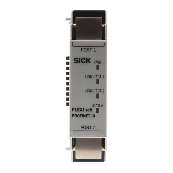
Page 85: Interfaces And Operation
(can be switched off, see below) Error elimination is described in section 5.4.7 “Diagnostics and troubleshooting” on Note page 100. 8012664/XB29/2013-06-11 © SICK AG • Industrial Safety Systems • Germany • All rights reserved Subject to change without notice... -
Page 86: Basic Configuration - Assigning A Device Name And Ip Address
LED of the FX0-GPNT Activate the checkbox. After downloading the configuration, the LED will light up Green permanently, even if no PROFINET communication is established. This feature is only available with firmware O V2.00.0 and Flexi Soft Designer version Note O 1.4.0. - Page 87 Assign a unique plant specific name to the gateway by using either the network configu- ration tool, e.g. SIEMENS SIMATIC Manager or the Flexi Soft Designer tool. Using the plant specific (unique) name, the I/O controller (i.e. PLC) can now assign the IP address to the gateway before system boot.
-
Page 88: Profinet Configuration Of The Gateway - How The Data Are Transferred
Usually the IP address will be assigned by the PROFINET IO controller (e.g. PLC). However, the FX0-GPNT allows configuration of the entire Flexi Soft system over Ethernet TCP/IP. In this case, it may be necessary to assign an IP address to the gateway even before the PROFINET IO network has been setup. - Page 89 Flexi Soft Gateways Step 2: Add the gateway to the project In order to have the Flexi Soft system data available in the PLC process image, the gate- way must be added to the hardware configuration first. The procedure associated with this depends on the hardware configuration program of the PLC being used.
- Page 90 IO cycle tab and select the desired rate from the Update time pull-down menu. Fig. 43: Configuration of the update time of the FX0-GPNT © SICK AG • Industrial Safety Systems • Germany • All rights reserved 8012664/XB29/2013-06-11 Subject to change without notice...
- Page 91 Assign the device name to the gateway. Select PLC > Ethernet > Assign device name. The Assign device name dialog opens. From the Assign device name dialog, find and select the SICK gateway that you wish to assign the device name to in the list.
-
Page 92: Profinet Configuration Of The Gateway - Which Data Are Transferred
PROFINET configuration of the gateway — Which data are transferred Cyclic data The physical Flexi Soft I/O modules are not represented as typical hardware modules in the PROFINET IO hardware catalogue. Instead, the data available from the Flexi Soft sys- tem has been organized into data blocks. - Page 93 There are five (5) output data blocks, 10 bytes each. The content of these data blocks can be used as input in the Flexi Soft logic editor or can be routed via a second gateway into another network. In order to have the desired bits available for routing or in the logic editor, tag names have to be defined for each bit that shall be used.
- Page 94 Byte 57 Module 13 and 14 are always Byte 58 the gateways. Byte 59 Length 32 bytes 60 bytes 60 bytes © SICK AG • Industrial Safety Systems • Germany • All rights reserved 8012664/XB29/2013-06-11 Subject to change without notice...
- Page 95 Alarms can be read acyclically through the PROFINET IO alarms infrastructure. Once an error occurs on any Flexi Soft module, the PROFINET IO gateway raises the appropriate diagnostic alarm to the network. This will trigger the fault LED on the PLC, and make the specifics (text and help) of the diagnostic alarm available through the SIMATIC PLC inter- face.
- Page 96 0304 Configuration of this module is valid 0305 Communication from the network 0306 Communication to the network 0307 … 0331 Reserved © SICK AG • Industrial Safety Systems • Germany • All rights reserved 8012664/XB29/2013-06-11 Subject to change without notice...
- Page 97 0F04 Configuration of this module is valid 0F05 Communication from the network 0F06 Communication to the network 0F07 … 0F31 Reserved 8012664/XB29/2013-06-11 © SICK AG • Industrial Safety Systems • Germany • All rights reserved Subject to change without notice...
- Page 98 The status of this bit can be defined to suit the specific application in the MOCx logic, e.g. to indicate inadmissible movements of an axis that have been detected by an MOCx function block. © SICK AG • Industrial Safety Systems • Germany • All rights reserved 8012664/XB29/2013-06-11...
-
Page 99: Tcp/Ip Configuration Interface
See section 5.1.1 “TCP/IP configuration interface” on page 32. 5.4.6 Ethernet TCP/IP socket interface See section 5.1.2 “Ethernet TCP/IP socket interface” on page 37. 8012664/XB29/2013-06-11 © SICK AG • Industrial Safety Systems • Germany • All rights reserved Subject to change without notice... -
Page 100: Diagnostics And Troubleshooting
10). If the error remains, replace the gateway. With firmware O V2.00.0 the red/green flashing of the STATUS LED can be disabled in the Flexi Soft Designer. In this case, the STATUS LED is Green permanently, if the configuration is valid. -
Page 101: Ethercat Gateway
You will find the ESI file and the device icon for PLC interfacing with EtherCAT support … in the Internet on the FX0-GETC product page on www.sick.com. in the Flexi Soft Designer program folder on your hard disk (default installation folder is “C:\programs\SICK\FlexiSoft\DeviceDescriptions\...”). - Page 102 Ethernet cable, max. length 100 m according to DIN EN 50 173 use of core pairs 1/2 and 3/6 screened cables are recommended © SICK AG • Industrial Safety Systems • Germany • All rights reserved 8012664/XB29/2013-06-11 Subject to change without notice...
-
Page 103: Installation Of The Gateway In The Flexi Soft System
5.5.2 Installation of the gateway in the Flexi Soft system This section outlines the basic steps to install the gateway in the Flexi Soft system. More detailed information will be given in the following sections. Add the gateway to a Flexi Soft system Mount the gateway as described in section 4.1.1 “Steps for mounting the modules”... -
Page 104: Ethercat Configuration Of The Gateway
EtherCAT network configuration tool (e.g. TwinCAT) for the first time, the ESI file of the gateway must be installed into the hardware catalogue of the tool. You will find the ESI file in the Flexi Soft Designer program folder (default folder is “C:\programs\SICK\FlexiSoft\DeviceDescriptions\FX0-GETC_ESI”). - Page 105 I.e. only one of these five input PDOs can be active at any time. There is one input PDO for 10 byte input data (1 data set used in the Flexi Soft Designer), one for 20 byte data (2 data sets used) etc. up to the maximum of 50 byte.
- Page 106 PDO configuration is predefined and can not be changed. Fig. 50: PDO configuration in the EtherCAT network confi- guration tool © SICK AG • Industrial Safety Systems • Germany • All rights reserved 8012664/XB29/2013-06-11 Subject to change without notice...
-
Page 107: Input Data - Flexi Soft To Ethercat
Similar to the input data, the output data are divided into five data sets. Each output data set contains 10 bytes. Notes The contents of the output data sets can be configured in the Flexi Soft Designer confi- guration software. See section 7.3.6 “Output data configuration (Network to Flexi Soft)” on page 180. -
Page 108: Tag Name Export
5.5.6 Tag name export The Flexi Soft Designer allows you to export the names of the bits used in the input and output data sets. Before exporting you can also edit the start addresses for the used data sets in the PLC. The exported tag names and start addresses can then be imported as variables to the application program in the EtherCAT network configuration tool (e.g. - Page 109 Flexi Soft Gateways How to change the start address for the data sets: Open the Flexi Soft Designer and load the hardware configuration including the EtherCAT gateway. Ensure your project is offline. Click on the Gateways button above the main window and select the FX0-GETC or double click the FX0-GETC in the hardware configuration view to open the gateway configuration dialog.
-
Page 110: Ethernet Over Ethercat (Eoe)
Follow the instructions in the online help or in the user manual of your EtherCAT network configuration tool for assigning an IP address and a subnet mask. If the EtherCAT master and the Flexi Soft Designer are running on different PCs, then TCP/IP routing must be enabled in the Flexi Soft Designer. -
Page 111: Coe (Can Application Layer Over Ethercat)
The CoE objects can only be read, i.e. it is not possible to change the input or output process data or other CoE objects via SDO commands. 8012664/XB29/2013-06-11 © SICK AG • Industrial Safety Systems • Germany • All rights reserved Subject to change without notice... - Page 112 Flexi Soft Gateways Input process data (2000h) This object contains the input process data from the Flexi Soft system to an EtherCAT PLC and makes them available for acyclic usage. It corresponds to the EtherCAT input PDO data of the FX0-GETC.
- Page 113 The ASCII string is “module xx +” or “module xx -”, where xx stands for the position in the Flexi Soft system of the module that has generated the diagnosis message. Coming diag- nosis messages are marked with a “+”, going diagnosis messages are marked with a “-”.
-
Page 114: Diagnostics And Troubleshooting
Operating Instructions Flexi Soft Gateways 5.5.10 Diagnostics and troubleshooting The FX0-GETC provides the following module status bits in the Flexi Soft system for diag- nostic purposes. The module number of the FX0-GETC is 16. Tab. 81: Module status bits Error message... - Page 115 Ethernet gateways Operating Instructions Chapter 5 Flexi Soft Gateways For information how to perform diagnostics on the Flexi Soft system please refer to the operating instructions for the Flexi Soft Designer software (SICK part no. 8012998). Tab. 82: Troubleshooting for Error...
-
Page 116: Fieldbus Gateways
Fieldbus gateways Chapter 6 Operating Instructions Flexi Soft Gateways Fieldbus gateways PROFIBUS DP gateway The following Flexi Soft gateway can be used for PROFIBUS DP: FX0-GPRO. 6.1.1 Interfaces and operation Controls and status indicators Fig. 56: Controls and status indicators FX0-GPRO... - Page 117 The address that can be set via the hardware address switch ranges from 1 … 99. Notes The address that can be set via the Flexi Soft Designer software ranges from 3 … 125. The PROFIBUS master cannot overwrite the address.
- Page 118 Capacitance per unit length < 30 pF/m Loop resistance a 110 `/km Core diameter > 0.64 mm Core cross-section > 0.34 mm © SICK AG • Industrial Safety Systems • Germany • All rights reserved 8012664/XB29/2013-06-11 Subject to change without notice...
-
Page 119: Planning
On loading configurations that have been prepared using a version of Flexi Soft Designer < 1.3.1 the check box is cleared. In the case of configurations that have been prepared using Flexi Soft Designer 1.3.1 or higher, the check box is selected. - Page 120 The data blocks 1-4 contain 12 bytes each, data block 5 contains 2 bytes. The contents of the data blocks are freely selectable, but are preconfigured in the Flexi Soft Designer configuration software: © SICK AG • Industrial Safety Systems • Germany • All rights reserved 8012664/XB29/2013-06-11 Subject to change without notice...
- Page 121 “Data transmitted into the network (input data sets)” on page 14. How to set the start address for the data blocks: Open the Flexi Soft Designer and load the hardware configuration including the PROFIBUS DP gateway. Ensure your project is offline.
-
Page 122: Profibus Configuration Of The Gateway - How The Data Are Transferred
Click OK to accept the new start address. For further information on how to configure the process image, see chapter 7 “Layout and content of the process image” on page 173 and the Flexi Soft Designer operating instruc- tions (SICK part no. 8012998). - Page 123 Flexi Soft. Step 2: Add the gateway to the project In order to have the Flexi Soft system data available in the PLC process image, the gate- way must be added to the hardware configuration first. The procedure associated with this depends on the hardware configuration program of the PLC being used.
- Page 124 (6 bytes) device related diagnostics: status messages or manufacturer specific messages Each Flexi Soft module supports a unique module ID. Based on this ID the gateway deter- mines the manufacturer specific diagnostics number. This way it is possible to retrieve module specific diagnostics texts from the GSD file.
- Page 125 12.4 Configuration of this module is valid 12.5 Communication from the network 12.6 Communication to the network 12.7 … 15.7 Reserved 8012664/XB29/2013-06-11 © SICK AG • Industrial Safety Systems • Germany • All rights reserved Subject to change without notice...
- Page 126 12.4 Configuration of this module is valid 12.5 Communication from the network 12.6 Communication to the network 12.7 … 15.7 Reserved © SICK AG • Industrial Safety Systems • Germany • All rights reserved 8012664/XB29/2013-06-11 Subject to change without notice...
- Page 127 The status of this bit can be defined to suit the specific application in the MOCx logic, e.g. to indicate inadmissible movements of an axis that have been detected by an MOCx function block. 8012664/XB29/2013-06-11 © SICK AG • Industrial Safety Systems • Germany • All rights reserved Subject to change without notice...
- Page 128 Summary of bits 12.5 to 12.7 23 … 3F Other module 12.3 Reserved 12.4 Configuration of this module is valid 12.5 … 15.7 Reserved © SICK AG • Industrial Safety Systems • Germany • All rights reserved 8012664/XB29/2013-06-11 Subject to change without notice...
-
Page 129: Diagnostics And Troubleshooting
Chapter 6 Flexi Soft Gateways 6.1.4 Diagnostics and troubleshooting For information how to perform diagnostics on the Flexi Soft system please refer to the operating instructions for the Flexi Soft Designer software (SICK part no. 8012998). Tab. 93: Troubleshooting for Error... -
Page 130: Canopen Gateway
Configuration required or in progress Red (2 Hz) Critical fault, caused by gateway itself For diagnostics see section 6.2.14 “Diagnostics and troubleshooting” on page 159. © SICK AG • Industrial Safety Systems • Germany • All rights reserved 8012664/XB29/2013-06-11 Subject to change without notice... - Page 131 10 position rotary switch for setting the module address (ones) How to set the baud rate via hardware DIP switches: Set the baud rate using the DIP switches on the device. Then switch the Flexi Soft system off and back on again.
- Page 132 The address that can be set via the hardware address switch ranges from 1 … 99. Notes The address that can be set via the Flexi Soft Designer software ranges from 1 … 127. The CANopen master cannot overwrite the address.
-
Page 133: Canopen Configuration Of The Gateway - How The Data Are Transferred
You will find the EDS file and device icon for PLC interfacing … in the Internet on the FX0-GCAN product page. in the Flexi Soft Designer program folder on your hard disk (default installation folder is “C:\programs\SICK\FlexiSoft\DeviceDescriptions\...”). 6.2.2 CANopen configuration of the gateway —... - Page 134 Select the EDS file for the FX0-GCAN and click on the Open button. Step 2: Add the gateway to the controller In order to have the Flexi Soft system data available in the PLC process image, the gate- way must be added to the hardware configuration first. The procedure associated with this depends on the hardware configuration program of the PLC being used.
- Page 135 149 and to the manual for your CANopen system confi- guration software. Repeat this for the other Send-PDOs as well as for the Receive-PDOs. 8012664/XB29/2013-06-11 © SICK AG • Industrial Safety Systems • Germany • All rights reserved Subject to change without notice...
-
Page 136: Canopen Configuration Of The Gateway - Which Data Are Transferred
Request), followed by the Data Length Code (DLC), followed by 0 to 8 data bytes. The DLC (4 bits) indicates the number of data bytes. © SICK AG • Industrial Safety Systems • Germany • All rights reserved 8012664/XB29/2013-06-11 Subject to change without notice... -
Page 137: Nmt - Network Management
CANopen network (address = 0): Tab. 102: Example NMT CAN ID DATA object for resetting all communication 8012664/XB29/2013-06-11 © SICK AG • Industrial Safety Systems • Germany • All rights reserved Subject to change without notice... -
Page 138: Sync
Module number of the module causing the error (see Tab. 105) 4 bytes module specific status bits (see Tab. 105). Active bits are M2 … M5 high (=“1”) © SICK AG • Industrial Safety Systems • Germany • All rights reserved 8012664/XB29/2013-06-11 Subject to change without notice... - Page 139 Summary of bits 05 to 07 Reserved Configuration of this module is valid Communication from the network Communication to the network 8012664/XB29/2013-06-11 © SICK AG • Industrial Safety Systems • Germany • All rights reserved Subject to change without notice...
- Page 140 Reserved EtherCAT gateway Configuration of this module is valid Communication from the network Communication to the network 07 … 31 Reserved © SICK AG • Industrial Safety Systems • Germany • All rights reserved 8012664/XB29/2013-06-11 Subject to change without notice...
- Page 141 The status of this bit can be defined to suit the specific application in the MOCx logic, e.g. to indicate inadmissible movements of an axis that have been detected by an MOCx function block. 8012664/XB29/2013-06-11 © SICK AG • Industrial Safety Systems • Germany • All rights reserved Subject to change without notice...
-
Page 142: Node Guarding
Tab. 119 “Supported SDOs” on page 146), at least one node guarding message must be received within the configured consumer heartbeat time (typically from an NMT master). © SICK AG • Industrial Safety Systems • Germany • All rights reserved 8012664/XB29/2013-06-11 Subject to change without notice... -
Page 143: Pdo Communication
“Data transmitted into the network (input data sets)” on page 14. For further information on how to configure the process image, see chapter 7 “Layout and content of the process image” on page 173 and the Flexi Soft Designer operating instruc- tions (SICK part no. 8012998). - Page 144 281-2FF 381-3FF 481-4FF B1…B32: CAN telegram bytes as mapped into the network input data using the Flexi Soft Designer software (see 7.3 “Customizing the operational data (Flexi Soft to Network)” on page 175). The gateway sends one or more TxPDOs if at least one of the following occurs: At least one input or output byte has changed its value and the transmission type for the TxPDO containing this byte has the value 255.
-
Page 145: Sdo Communication
This applies also to the SDO index in data byte 2 and 3 which has the data type UINT. I.e. Note the low byte is transferred in data byte 2 and the high byte is transferred in data byte 3. 8012664/XB29/2013-06-11 © SICK AG • Industrial Safety Systems • Germany • All rights reserved Subject to change without notice... -
Page 146: Sdo Object Directory
Process data output objects You can find more detailed information on these SDOs in the CANopen draft standard DS 301 V4.02 (DSP 301 V4.1). © SICK AG • Industrial Safety Systems • Germany • All rights reserved 8012664/XB29/2013-06-11 Subject to change without notice... - Page 147 0. If after activation of the life guarding the guard time or the life time factor is set to 0, life guarding is deactivated. See also section 6.2.11 “Guarding protocols” on page 153. 8012664/XB29/2013-06-11 © SICK AG • Industrial Safety Systems • Germany • All rights reserved Subject to change without notice...
- Page 148 Software version of the device Serial number UDINT Serial number of the device SDO 1027: Module list The module list contains the module type and the module ID of all Flexi Soft modules in the system. Tab. 121: SDO 1027 Subindex Module...
- Page 149 0609 0030h, invalid parameter value). SDO 1600…1603: RxPDO mapping parameters This SDO can not be used since the RxPDO mapping is done using the Flexi Soft Designer. See also Tab. 110 and Tab. 112. SDO 1800…1803: TxPDO communication parameters Using SDO 1800 to 1803 the communication parameters for the TxPDOs 1 to 4 are configured.
- Page 150 Operating Instructions Flexi Soft Gateways SDO 1A00…1A03: TxPDO mapping parameters This SDO can not be used since the TxPDO mapping is done using the Flexi Soft Designer. See also Tab. 110 and Tab. 111. SDO 3100: Module status bits SDO 3100 contains the module status bits from the Flexi Soft system (see Tab. 105).
- Page 151 Flexi Soft Gateways SDO 3300: Module type code array SDO 3300 contains the type codes of the max. 15 modules in the Flexi Soft system in SINT format (8 bytes per module = 120 bytes). See the following table for details.
- Page 152 RxPDO 1, Byte 8 6000,9-16 RxPDO 2, Byte 1-8 6000,17-24 RxPDO 3, Byte 1-8 6000,25-32 RxPDO 4, Byte 1-8 SDO 6000 is write-only. © SICK AG • Industrial Safety Systems • Germany • All rights reserved 8012664/XB29/2013-06-11 Subject to change without notice...
-
Page 153: Guarding Protocols
Always use either node guarding or heartbeat! According to the CIA CANopen specification DS 301 guarding is mandatory. Please activate either node guarding or heartbeat. If no guarding is configured the Flexi Soft system can WARNING not detect an interruption of the CANopen communication, e.g. a broken network cable. In this case the CANopen gateway’s input and output data may be frozen. - Page 154 Heartbeat and node guarding/life guarding can not be used simultaneously. If the configuration is changed from activated life guarding to no life guarding or vice versa a complete power reset of the Flexi Soft system is required to setup the CANopen network communication properly.
-
Page 155: Error Objects
NMT master has occurred or the has detected a cable 0, 0, 0, 0, 0 CAN cable is broken. break Check the CANopen master. Check cabling. 8012664/XB29/2013-06-11 © SICK AG • Industrial Safety Systems • Germany • All rights reserved Subject to change without notice... -
Page 156: Canopen Diagnostics Examples
Data length code: 8 bytes follow. Expedited upload request 00 31: Index 3100 Subindex 02: module in position 1 (see Tab. 125) © SICK AG • Industrial Safety Systems • Germany • All rights reserved 8012664/XB29/2013-06-11 Subject to change without notice... - Page 157 03 10: Index 1003 Subindex 01: last error Module status bit 30 (bit 6 of byte M2 = 0: output 4 stuck at high 8012664/XB29/2013-06-11 © SICK AG • Industrial Safety Systems • Germany • All rights reserved Subject to change without notice...
- Page 158 Error byte M5, bit 2 = 0: external error Error byte M4, bit 0 = 0: input 1-2 dual channel input evaluation: error detected (see Tab. 105) © SICK AG • Industrial Safety Systems • Germany • All rights reserved 8012664/XB29/2013-06-11 Subject to change without notice...
-
Page 159: Diagnostics And Troubleshooting
Module status bit 8 (bit 0 of byte M4) = 0: input 1-2 dual channel input evaluation: error detected 6.2.14 Diagnostics and troubleshooting For information on how to perform diagnostics on the Flexi Soft system please refer to the operating instructions for the Flexi Soft Designer software (SICK part no. 8012998). Tab. 132: Troubleshooting for Error... -
Page 160: Devicenet Gateway
I/O Messaging (Polled or Change of State/Cyclic) also fragmented baud rate adjustable via DIP switch (125 kbit/s, 250 kbit/s, 500 kbit/s) © SICK AG • Industrial Safety Systems • Germany • All rights reserved 8012664/XB29/2013-06-11 Subject to change without notice... -
Page 161: Interfaces And Operation
Configuration required or in progress Red (2 Hz) Critical fault, caused by gateway itself For diagnostics see section 6.3.7 “Diagnostics and troubleshooting” on page 171. 8012664/XB29/2013-06-11 © SICK AG • Industrial Safety Systems • Germany • All rights reserved Subject to change without notice... - Page 162 DIP 3 DIP 4 on the FX0-GDEV If all DIP switches are set to Off, then the setting for the baud rate in Flexi Soft Designer Notes is used. All other DIP switch settings will set the baud rate to 125 kbit/s.
- Page 163 The address that can be set via the Flexi Soft Designer software ranges from 0-63. The DeviceNet master cannot overwrite the address. If the DeviceNet address and the baud rate are set using the Flexi Soft Designer, the settings will become effective immediately after transferring the configuration (i.e.
-
Page 164: Setting Up Devicenet Communication
You will find the EDS file and device icon for PLC interfacing … in the Internet on the FX0-GDEV product page. in the Flexi Soft Designer program folder on your hard disk (default installation folder is “C:\programs\SICK\FlexiSoft\DeviceDescriptions\...”). Download the EDS file and device icon from www.sick.com, on the FX0-GDEV product page. - Page 165 Fig. 80: Selection of input data set 1 and output data set 1 using DeviceNetManager from Allen Bradley 8012664/XB29/2013-06-11 © SICK AG • Industrial Safety Systems • Germany • All rights reserved Subject to change without notice...
-
Page 166: Supported Devicenet Features
For information how to define and customize the content and tag names of the input and output data sets please see chapter 7 “Layout and content of the process image” on page 173 and the operating instructions for the Flexi Soft Designer software (SICK part no. 8012998). -
Page 167: Devicenet Protocol Settings
Input data set 2-4 Input data set 3-4 Input data set 3 Input data set 3-4 Input data set 4 Input data set 4 8012664/XB29/2013-06-11 © SICK AG • Industrial Safety Systems • Germany • All rights reserved Subject to change without notice... - Page 168 Tab. 142: Individual Input Service code Implemented in Class Implemented in Instance Service name Data Set Transfer object Get_Attributes_All (73h) general services Get_Attribute_Single © SICK AG • Industrial Safety Systems • Germany • All rights reserved 8012664/XB29/2013-06-11 Subject to change without notice...
- Page 169 Module status module 0 UINT[2] (73h) instance 3 attribute definitions Module status module 1 UINT[2] … … … Module status module 14 UINT[2] 8012664/XB29/2013-06-11 © SICK AG • Industrial Safety Systems • Germany • All rights reserved Subject to change without notice...
- Page 170 Data set parameter Size Data Set Transfer object Reserved UINT[2] (73h) instance 4 attribute definitions Reserved UINT[2] … … … Reserved UINT[2] © SICK AG • Industrial Safety Systems • Germany • All rights reserved 8012664/XB29/2013-06-11 Subject to change without notice...
-
Page 171: Diagnostics And Troubleshooting
Flexi Soft Gateways 6.3.7 Diagnostics and troubleshooting For information on how to perform diagnostics on the Flexi Soft system please refer to the operating instructions for the Flexi Soft Designer software (SICK part no. 8012998). Tab. 147: Troubleshooting for Error... - Page 172 Module connecting plug is soiled or Repower the system. damaged. Check the other Flexi Soft modules. Other Flexi Soft module has internal critical error. © SICK AG • Industrial Safety Systems • Germany • All rights reserved 8012664/XB29/2013-06-11 Subject to change without notice...
-
Page 173: Layout And Content Of The Process Image
Layout and content of the process image Routing The process image transmitted by the Flexi Soft gateways into the network consists of the operational data (e.g. logic results, input and output states) and the diagnostics data (e.g. module status, CRCs). These data are organised in 4 data sets. -
Page 174: Default Settings For The Operational Data
For the FX0-GCAN please see Tab. 110 on page 143. The default byte assignment can be freely customized as described in the following section. © SICK AG • Industrial Safety Systems • Germany • All rights reserved 8012664/XB29/2013-06-11 Subject to change without notice... -
Page 175: Customizing The Operational Data (Flexi Soft To Network)
You will find more detailed information in the Flexi Soft Designer software operating instructions (SICK part no. 8012998). In the delivery status, the data routing configuration of the Flexi Soft gateways is shown in the gateway configuration dialog. -
Page 176: The Toolbar
In the default configuration, only the first logic result byte (Logic result 0) is active and available. You can activate more logic result output bits in the logic editor (see the Flexi Soft software operating instructions, SICK part no. 8012998). -
Page 177: Gateway Data Set To Network Area
(e.g. for extension modules). In the Tag names area of the Flexi Soft to Network configuration dialog, it is not possible to edit tag names, with the exception of the gateway direct outputs (see the following section). -
Page 178: Gateway Direct Output Values
Enter tag names for the individual bits of the selected byte that you want to use as gateway direct output values. © SICK AG • Industrial Safety Systems • Germany • All rights reserved 8012664/XB29/2013-06-11 Subject to change without notice... - Page 179 All bits of the selected byte with a tag name will now appear in the logic editor in the Outputs file card. You can edit the predefined gateway direct output values in the same way. Note 8012664/XB29/2013-06-11 © SICK AG • Industrial Safety Systems • Germany • All rights reserved Subject to change without notice...
-
Page 180: Output Data Configuration (Network To Flexi Soft)
For each bit of the selected byte that you wish to use, enter a tag name in the Tag names area. © SICK AG • Industrial Safety Systems • Germany • All rights reserved 8012664/XB29/2013-06-11 Subject to change without notice... -
Page 181: Saving And Loading A Configuration
You can not undo this action. The Import button is only available for the Network to gateway routing configuration. Note 8012664/XB29/2013-06-11 © SICK AG • Industrial Safety Systems • Germany • All rights reserved Subject to change without notice... -
Page 182: Monitoring The Operational Data Online
Click on the Flexi Soft to Network or the Network to Flexi Soft tab on the left hand menu to display the routing view for the input or output data you want to monitor. -
Page 183: Technical Specifications
EtherCAT application cycle time 4 ms Watchdog Time Process Data O 5 ms Watchdog Time Process Data Interface O 55 ms (PDI) 8012664/XB29/2013-06-11 © SICK AG • Industrial Safety Systems • Germany • All rights reserved Subject to change without notice... -
Page 184: Profibus Dp
In order to set the slave address via software, the hardware setting for the address must be “00”. In order to set the slave address via software, the hardware setting for the address must be “00”. © SICK AG • Industrial Safety Systems • Germany • All rights reserved 8012664/XB29/2013-06-11... -
Page 185: Devicenet
FX0-GETC – – In order to set the slave address via software, the hardware setting for the address must be “00”. 8012664/XB29/2013-06-11 © SICK AG • Industrial Safety Systems • Germany • All rights reserved Subject to change without notice... -
Page 186: General Technical Specifications
FLEXBUS+ connection (internal bus) Number of poles Connectors 1 plug left, 1 socket right Mounting rail DIN mounting rail acc. to EN 60 715 © SICK AG • Industrial Safety Systems • Germany • All rights reserved 8012664/XB29/2013-06-11 Subject to change without notice... -
Page 187: Dimensional Drawings
8.4.1 Dimensional drawing FX0-GENT, FX0-GMOD, FX0-GPNT and FX0-GETC Fig. 91: Dimensional drawing FX0-GENT, FX0-GMOD, FX0>GPNT and FX0-GETC (mm) 93.3 96.5 86.5 8012664/XB29/2013-06-11 © SICK AG • Industrial Safety Systems • Germany • All rights reserved Subject to change without notice... -
Page 188: Dimensional Drawing Fx0-Gpro, Fx0-Gcan And Fx0-Gdev
Modbus TCP 1044073 FX0-GMOD PROFINET IO 1044074 FX0-GPNT PROFIBUS DP 1044075 FX0-GPRO CANopen 1044076 FX0-GCAN DeviceNet 1044077 FX0-GDEV EtherCAT 1051432 FX0-GETC © SICK AG • Industrial Safety Systems • Germany • All rights reserved 8012664/XB29/2013-06-11 Subject to change without notice... -
Page 189: Annex
Annex Operating Instructions Chapter 9 Flexi Soft Gateways Annex EC declaration of conformity Fig. 93: EC declaration of conformity (page 1) 8012664/XB29/2013-06-11 © SICK AG • Industrial Safety Systems • Germany • All rights reserved Subject to change without notice... - Page 190 Annex Chapter 9 Operating Instructions Flexi Soft Gateways Fig. 94: EC declaration of conformity (page 2) © SICK AG • Industrial Safety Systems • Germany • All rights reserved 8012664/XB29/2013-06-11 Subject to change without notice...
-
Page 191: List Of Tables
Number of possible connections................61 Tab. 39: Configuration guideline — Gateway as master .............61 Tab. 40: Configuration guideline — Gateway as slave ............61 8012664/XB29/2013-06-11 © SICK AG • Industrial Safety Systems • Germany • All rights reserved Subject to change without notice... - Page 192 FX0-GETC Output Process Data CoE object 2001h ...........112 Tab. 78: FX0-GETC CRC CoE object 2002h...............112 Tab. 79: FX0-GETC Status and Diagnosis CoE object 2003h ..........112 © SICK AG • Industrial Safety Systems • Germany • All rights reserved 8012664/XB29/2013-06-11 Subject to change without notice...
- Page 193 Tab. 118: Example — Read SDO confirmation..............146 Tab. 119: Supported SDOs ....................146 Tab. 120: SDO 1018 contents..................... 148 Tab. 121: SDO 1027 contents..................... 148 8012664/XB29/2013-06-11 © SICK AG • Industrial Safety Systems • Germany • All rights reserved Subject to change without notice...
- Page 194 Tab. 154: Technical specifications FX0-GDEV..............185 Tab. 155: Technical specifications supply circuit ...............185 Tab. 156: General technical specifications .................186 Tab. 157: Ordering information Flexi Soft gateways............188 © SICK AG • Industrial Safety Systems • Germany • All rights reserved 8012664/XB29/2013-06-11 Subject to change without notice...
-
Page 195: List Of Illustrations
Interfaces and display elements of the FX0RGPNT ..........85 Fig. 40: Disabling the STATUS LED of the FX0-GPNT............86 Fig. 41: PROFINET IO gateway configuration dialog............87 8012664/XB29/2013-06-11 © SICK AG • Industrial Safety Systems • Germany • All rights reserved Subject to change without notice... - Page 196 DeviceNetManagerTM from Allen Bradley............165 Fig. 81: Selection of input data set 3 and output data set 1-5 using DeviceNetManagerTM from Allen Bradley............166 © SICK AG • Industrial Safety Systems • Germany • All rights reserved 8012664/XB29/2013-06-11 Subject to change without notice...
- Page 197 Dimensional drawing FX0-GPRO, FX0-GCAN and FX0-GDEV (mm)....188 Fig. 93: EC declaration of conformity (page 1)..............189 Fig. 94: EC declaration of conformity (page 2)..............190 8012664/XB29/2013-06-11 © SICK AG • Industrial Safety Systems • Germany • All rights reserved Subject to change without notice...
- Page 198 Annex Chapter 9 Operating Instructions Flexi Soft Gateways © SICK AG • Industrial Safety Systems • Germany • All rights reserved 8012664/XB29/2013-06-11 Subject to change without notice...
- Page 199 Annex Operating Instructions Chapter 9 Flexi Soft Gateways 8012664/XB29/2013-06-11 © SICK AG • Industrial Safety Systems • Germany • All rights reserved Subject to change without notice...
- Page 200 E-Mail support@sick.jp 1 800 325-7425 – tollfree Magyarország E-Mail info@sickusa.com Phone +36 1 371 2680 E-Mail office@sick.hu Nederlands Phone +31 (0)30 229 25 44 More representatives and agencies E-Mail info@sick.nl at www.sick.com SICK AG | Waldkirch | Germany | www.sick.com...
Need help?
Do you have a question about the Flexi Soft and is the answer not in the manual?
Questions and answers