
Related Manuals for Bistos BT-500


Summary of Contents for Bistos BT-500
- Page 1 BT-500 Infant Incubator BT-500 Keep this manual for future reference P/N : 500-ENG-OPM-EUR-R07...
- Page 2 Information furnished by Bistos Co., Ltd is believed to be accurate and reliable. However, no responsibility is assumed by Bistos for its use, or any infringements of patents or other rights of third parties that may result from its use. No license is granted by implication or otherwise under any patent or patent rights of Bistos.
-
Page 3: Table Of Contents
BT-500 Operation Manual Table of Contents 1. SAFETY .................... 4 1.1 Instructions for the Safe Operation and Use of the BT-500 ........ 4 1.2 Warnings ......................5 1.3 Shockh azards ....................12 1.4 General precaution on environment ..............13 1.5 Definitions and symbols ................... 15 2. - Page 4 6.5 Skin temperature sensors and SpO2 sensors ............. 65 6.6 Drain of residual water..................65 6.7 Regular Inspection .................... 66 6.8 Battery Replacement and Disposal ..............67 6.9 Disposal of the BT-500 ..................67 7. SPECIFICATION................68 8. TROUBLESHOOTING ..............72 8.1 General Checking ..................... 72 8.2 Alarm Message Checking .................
-
Page 5: Safety
Do not use the incubator if there is any visible sign of damage. Only the AC line cord supplied with the BT-500 is approved for use with the Unit. Do not attempt to service the BT-500 incubator. Only qualified service personnel by Bistos Co., Ltd. -
Page 6: Warnings
Use only Bistos recommended fuel cells for proper operation. Failure to do so could result in personal injury or equipment damage. - Page 7 For proper operation of the incubator, use only skin temperature probes from Bistos Co. Ltd. Using other probes could result in personal injury or equipment damage. Never place the skin temperature probe under the infant or use it ...
- Page 8 ) in the blood. When deemed advisable by the attending physician, measure blood pO by accepted clinical techniques. Failure to do so could result in personal injury or equipment damage. P/N : 500-ENG-OPM-EUR-R07 Bistos Co., Ltd. 2018,03...
- Page 9 Personal injury could occur. Phototherapy units located too close to the incubator may affect P/N : 500-ENG-OPM-EUR-R07 Bistos Co., Ltd. 2018,03...
- Page 10 Personal injury could occur. Always use two people when moving the incubator and patient together. When moving the incubator within the same floor space, check that the patient is secured safely in the unit and P/N : 500-ENG-OPM-EUR-R07 Bistos Co., Ltd. 2018,03...
- Page 11 Attach the incubator to the stand or the vertical height adjustable stand using the bolts provided. Failure to do so could result in the incubator separating from the stand if sufficiently tilted, particularly with the hood open. Personal injury or equipment P/N : 500-ENG-OPM-EUR-R07 Bistos Co., Ltd. 2018,03...
- Page 12 Inaccurate measurements may be caused by intravascular dyes such as indocyanine green or methylene blue. Inaccurate measurements or loss of pulse signal may be caused by excessive illumination. Inaccurate measurements may be caused by excessive patient P/N : 500-ENG-OPM-EUR-R07 Bistos Co., Ltd. 2018,03...
-
Page 13: Shockh Azards
Personal injury or equipment damage could occur. Do not expose the unit to excessive moisture that would allow for liquid pooling. Personal injury or equipment damage could occur. P/N : 500-ENG-OPM-EUR-R07 Bistos Co., Ltd. 2018,03... -
Page 14: General Precaution On Environment
0% to 95%. Avoid placing in an area Avoid placing in an where there is an area where there is an excessive humidity rise excessive shock or or ventilation problem. vibration. P/N : 500-ENG-OPM-EUR-R07 Bistos Co., Ltd. 2018,03... -
Page 15: Definitions And Symbols
1.5 Definitions and symbols Symbol Description Used to identify safety information. Be well-known this information thoroughly before using BT-500. During the operation, do not disconnect any cable. Indicate the warning for hot surface. Type BF Applied part Refer to operation manual. Read manual before placing the device. - Page 16 2007/47/EEC. This symbol indicates to not dispose the device together with unsorted municipal waste(for EU only). The solid bar symbol indicates that mains adapter is put on the market after 13 August 2005. P/N : 500-ENG-OPM-EUR-R07 Bistos Co., Ltd. 2018,03...
-
Page 17: Introduction
BT-500 Operation Manual Section 2 Introduction 2.1 General This chapter provides a general description of the BT-500 infant incubator including. Brief Device Description Product Features Model Configurations 2.2 Brief Device Description A mains electricity (AC-powered) unit designed to provide an enclosed controlled environment to maintain appropriate temperature and humidity levels mainly for premature infants and other newborns who cannot effectively regulate their body temperature. -
Page 18: Essential Performance
Movable incubator cradle with wheels (Standard) Basket Storage of medical equipment and (Optional) items which infant needs Basket Partition Partition of Basket (Optional) Measures temperature and humidity Sensor module inside the hood and infant’s body (Standard) temperature P/N : 500-ENG-OPM-EUR-R07 Bistos Co., Ltd. 2018,03... - Page 19 Measures infant’s SpO2 (Optional) Masimo Extension for Extend sensor cable SpO2 sensor (Optional) IV plate Plate to place items which infant needs (Optional) Shelf Plate to place items which infant needs (Optional) P/N : 500-ENG-OPM-EUR-R07 Bistos Co., Ltd. 2018,03...
-
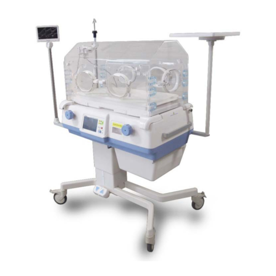
Page 20: Appearance Of Bt-500
**Oxygen control module is also available as an optional component. 2.7 Appearance of BT-500 2.7.1 BT-500 Front View Figure 2-1. BT-500 Front view ① Control Shell ② Hood ③ Sensor module ④... -
Page 21: Bt-500 Front View Detail
BT-500 Operation Manual 2.7.2 BT-500 Front View Detail Figure 2-2. BT-500 Front view details ① Console box ② Water tank draw ③ Tilting mechanism handle ④ Hood handle ⑤ Front access door ⑥ Baby desk with X-RAY Tray ⑦ Weighing scale ⑧... -
Page 22: Bt-500 Side View
BT-500 Operation Manual 2.7.4 BT-500 Side view Figure 2-4. BT-500 Left view ① Sensor Module, SpO2 sensor & External Communication port ② Main power switch ③ Main power AC connector ④ Incubator handle Figure 2-5. BT-500 Right view P/N : 500-ENG-OPM-EUR-R07 Bistos Co., Ltd. -
Page 23: Description Of Each Part
Operation Manual 2.8 Description of each part BT-500 is composed with several parts. The control shell is the part which controls the entire device. To measure the infant’s environment, the sensor module is needed. The hood is used to protect an infant from the external environment and maintain the internal environment of hood to best condition. -
Page 24: Hood
BT-500 Operation Manual 2.8.2 Hood The hood of BT-500 is an acrylic material. There is Access door in the front, rear and both sides of hood. Figure 2-8. Hood front view & Access door / side function Warning To prevent accidental disconnection, secure all patient leads, infusion lines, and ventilator tubing to the mattress with sufficient excess length to allow for the full range of mattress height adjustment. -
Page 25: Stand
Operation Manual 2.8.4 Stand BT-500 has two types of stand as fixed and lifting. Following figure show the fixed stand. Figure 2-12. Fixed Stand (Standard) In case of lifting type, you are able to adjust the vertical height using two sets of up/down arrow on footswitch. -
Page 26: Installation & Connection
BT-500 Operation Manual Section 3 Installation & Connection Attention to follow direction for installing BT-500. Use this device in 20~30 ℃ of environmental temperature and 0~90 % of humidity. Check the connection of the AC power cord and then use this cord, ... -
Page 27: Pole Assembly
3.1 IV pole Assembly The IV poles can be mounted as below. Check each Part name and number Part name ① IV ringer pole Assembly ② IV plate Assembly ③ IV External monitor Assembly ④ Shelf P/N : 500-ENG-OPM-EUR-R07 Bistos Co., Ltd. 2018,03... -
Page 28: Extenal Monitor
Machine Screw, M3x12 , pan head , stain-less steel ⑤ IV LCD FRAME ⑥ Lock washer, M6 , stain-less steel ⑦ Screw, M6x25 , Hex wrench , stain-less steel , (Hexagon wrench 5 mm) ⑧ LCD Monitor Ass’y Cable P/N : 500-ENG-OPM-EUR-R07 Bistos Co., Ltd. 2018,03... -
Page 29: Plate
Screw, M5x15 , Hexagon head bolt, stain-less steel (Hexagon wrench 4 mm) ⑩ Lock washer, M6 , stain-less steel ⑪ Screw, M6x25 , Hexagon head bolt , stain-less steel (Hexagon wrench 5 mm) P/N : 500-ENG-OPM-EUR-R07 Bistos Co., Ltd. 2018,03... -
Page 30: Ringer Ploe
Machine Screw, M3x12 , pan head , stain-less steel ④ IV LCD FRAME ⑤ Lock washer, M6 , stain-less steel ⑥ Screw, M6x25 , Hexagon head bolt , stain-less steel (Hexagon wrench 5 mm) P/N : 500-ENG-OPM-EUR-R07 Bistos Co., Ltd. 2018,03... -
Page 31: Air Filter Assembly
Total Ass’y ② Micro Filter ③ Filter Cover ④ Filter Cover Bolt WARNING Air filter exchange period is once in 3 month. Please check frequently and carefully that it is not dirty. P/N : 500-ENG-OPM-EUR-R07 Bistos Co., Ltd. 2018,03... -
Page 32: Connection Of Power And Cable
Connect 110V or 220V AC power cord to power, and connect the code to the power input terminal one side of the body below the BT-500 body. At that time, make sure latch the cord by using the locking device for prevent of unexpected separation. Afterward, it is operated by pushing the power switch located at the bottom of the front of the device shown as below. -
Page 33: Sensor Module Connection
2) Turn off all accessories plugged into the stand receptacles and remove accessories and items not in use during movement. 3) In case of VHA, adjust the stand to its lowest position prior to move the equipment. 4) Coil up the power cord and secure it. P/N : 500-ENG-OPM-EUR-R07 Bistos Co., Ltd. 2018,03... - Page 34 To install the BT-500 in desired place, you should lock the two casters on the stand. To lock a caster, lower the stopper on the caster to the locking position. To unlock a caster, raise the stopper.
-
Page 35: Operation
Section 4 Operation 4.1 System Start-up 1) Turn on the power switch in the bottom left of the BT-500 front. Figure 4-1. Power Switch 2) Then check the follow logo is displayed in the main LCD. Figure 4-2. Self Test Display P/N : 500-ENG-OPM-EUR-R07 Bistos Co., Ltd. - Page 36 If the O2 control option has been added to the main display screen it can be changed to control the O2 concentration inside the incubator. Figure 4-3. Main Display Figure 4-4 Main display (Setting the O2) P/N : 500-ENG-OPM-EUR-R07 Bistos Co., Ltd. 2018,03...
-
Page 37: Led
BT-500 Operation Manual This is a control panel of BT-500. Figure 4-5. Control panel 4.2 LED The following symbols are functions and descriptions of LEDs on the control panel. Symbol Name Description Mute When alarm situation is activated, using this key you can off Key &... -
Page 38: Key And Knob Operation
+0.1 ℃ or +1 % Rotate CW setting value -0.1 ℃ or -1 % Rotate CCW Push Select options / Finish selecting options Menu Rotate(CW/CCW) Shift options and change setting value Table 4-3. Use of Knob P/N : 500-ENG-OPM-EUR-R07 Bistos Co., Ltd. 2018,03... -
Page 39: Displays
BT-500 Operation Manual 4.4 Displays BT-500 provides the one display screen and the one dynamic Menu window together. Figure 4-6 is the basic layout of BT-500. Figure 4-6. Main operation display Figure 4-7. Basic screen of Main display (O2 control available) ①... - Page 40 37.1 ℃, skin mode, if setting temperature is above 37.6 ℃, the setting can be executed with [keylock] key. In case of sound icon, button to pause the alarm sound in case of the alarm Press the [Mute key] situation. P/N : 500-ENG-OPM-EUR-R07 Bistos Co., Ltd. 2018,03...
-
Page 41: Temperature Measurement And Control
4.5 Temperature Measurement and Control Measurement: Measurement of air temperature and skin temperature are starting at the same time of BT-500 power on. In case of skin temperature, especially, metal part of skin temperature sensor probe must be attached to the infant’s abdomen. - Page 42 To maintain the infant’s body temperature, the temperature of inside of the hood is controlled automatically. When using two skin temperature sensors, it is displayed as below figure 4-9. In order to use skin mode as the control mode, skin temperature 2 should be removed. P/N : 500-ENG-OPM-EUR-R07 Bistos Co., Ltd. 2018,03...
-
Page 43: Humidity Measurement And Control
Figure 4-9. Measurement and Control of Temperature (Skin mode) 4.6 Humidity Measurement and Control Measurement: Humidity measurement starts at the same time when BT-500 is powered on. Setting and Control The measured value is displayed on humidity region in upper middle of screen and the setting value is displayed on setting region in upper right of screen with sky-blue. -
Page 44: O2 Measurement
Use of anesthetic agents can interfere with oxygen analyzer accuracy. As oxygen use increases the danger or fire, do not place auxiliary equipment that produces sparks in an incubator. Personal injury or P/N : 500-ENG-OPM-EUR-R07 Bistos Co., Ltd. 2018,03... -
Page 45: Weighting Scale Measurement
Failure to do so could result in personal injury or equipment damage. 4.8 Weighting Scale Measurement Measurement: Weighting measurement starts at the same time when BT-500 is powered on. Measured data continuously displayed on lower part of screen in white Kg or pound unit according to set record. - Page 46 SpO2 Alarm delay refers to the delay time after an alarm condition occurs, an alarm sounds until the occurrence. You can set the delay time 0,5,10 and 15 seconds. And you can set PR Beep volume level. There are 5 different volume levels. P/N : 500-ENG-OPM-EUR-R07 Bistos Co., Ltd. 2018,03...
- Page 47 Masimo mode of external monitor in the monitor mode function. Read the chapter 4.11 to understand explanation of each monitor mode. In addition, set the Cam. Hor. Mirror to reverse the display from side to side. P/N : 500-ENG-OPM-EUR-R07 Bistos Co., Ltd. 2018,03...
- Page 48 If the PR value is higher than this value, an alarm is High PR Alarm occurring. limit If the PR value is lower than this value, an alarm is occurring. P/N : 500-ENG-OPM-EUR-R07 Bistos Co., Ltd. 2018,03...
- Page 49 BT-500 Operation Manual Figure 4-21. SpO2 Item ⑥ Help : BT-500 provide the simple information about the equipment. The information is as follow: - parts of full set BT-500 - main control panel and main display - how to use and change mode and parameters P/N : 500-ENG-OPM-EUR-R07 Bistos Co., Ltd.
- Page 50 ⑦ Scale : If weighing scale module is connected, a menu of weight calibration appears. Press the [keylock] button to unlock and press the [Menu key] button more than 2 seconds then, the menu will be displayed. P/N : 500-ENG-OPM-EUR-R07 Bistos Co., Ltd. 2018,03...
-
Page 51: Pulse Oximeter
The pulse oximeter of BT-500 as well as traditional pulse oximetry determines SpO2 by passing red and infrared light into a capillary bed and measuring changes in light absorption during the pulsatile cycle. - Page 52 This entire sequence is repeated once every two seconds on the most recent four seconds of raw data. The MS board SpO therefore corresponds to a running average of arterial hemoglobin saturation that is updated every two seconds. P/N : 500-ENG-OPM-EUR-R07 Bistos Co., Ltd. 2018,03...
- Page 53 MS board pulse oximeter. In all circumstance the MS board pulse oximeter must be connected to a grounded AC power supply. The MS board pulse oximeter is referred to as an IEC 60601/F device in the summary of situations table contained in IEC 60601-1-1. P/N : 500-ENG-OPM-EUR-R07 Bistos Co., Ltd. 2018,03...
-
Page 54: External Monitor
4.12 External Monitor BT-500 uses external 7” Color TFT LCD monitor that displays measured values from the control and video of infant inside the hood. Cam mode, Graph mode and Massimo mode are shown as below (1) Cam Mode: Air temperature, skin temperature, humidity, oxygen concentration and weighting scale are displayed on external monitor with real-time video of infant. - Page 55 (3) Masimo Mode: Air temperature, skin temperature, humidity, oxygen concentration and weighting scale are basically displayed. SpO2 and PR are mainly displayed. (c) Masimo Mode Figure 4-25. External Monitor Display Parameter Region Information Region P/N : 500-ENG-OPM-EUR-R07 Bistos Co., Ltd. 2018,03...
-
Page 56: Shut Down
Section 8. 4.13 Shut down To ensure safe terminating operation of BT-500, follow as below. 1) Turn off the Power switch to power down the incubator. 2) Turn off the main power source. P/N : 500-ENG-OPM-EUR-R07 Bistos Co., Ltd. -
Page 57: Calibration Of O2 Module
4.14 Calibration of O2 module Follow the direction to set and control O2 concentration for improving accuracy in the hood of BT-500. Calibration of O2 concentration 21 % : Calibrate O2 concentration to atmospheric oxygen concentration as the standard. 1) Move the position of the sensor module to O2 calibration position. At this time, alarm can be occurred. - Page 58 9) If it is indicated as “Done” massage, calibration completes the work. Otherwise, it is indicated as “Fail” massage, check the O2 sensor and atmospheric oxygen whether normal concentration. 10) Move the sensor module to normal position. P/N : 500-ENG-OPM-EUR-R07 Bistos Co., Ltd. 2018,03...
-
Page 59: Alarms
Section Alarms Alarm of BT-500 indicates the failure condition of equipment. According to each alarm condition, alarm messages are displayed on the front LCD. At the same time, alarm sound is caused and sensor module’s LED blinks. Also all setting values for alarm condition do not changed by any interrupt such as power on and off. -
Page 60: Temperature Alarms
Sensor module is not placed in the proper position. Table 5-1. System alarm message When Hood doors are open or close, BT-500 shows the condition through icons instead of alarm sound. Front and rear doors are open. Front and rear doors are close open Door open/close icon Front door is open. - Page 61 ±0.5 ℃ when the setting temperature is under 37 ℃. ② In case the measured temperature reaches more than 39.5 ℃ ±0.5 ℃ when the setting temperature is over 37 ℃. Table 5-3. Temperature alarm message P/N : 500-ENG-OPM-EUR-R07 Bistos Co., Ltd. 2018,03...
-
Page 62: Humidity Alarms
Weighting Scale alarms Messages display Sound Descriptions flash Weigh in excess of 10kg is on the mattress. Table 5-6. Weighting alarm message P/N : 500-ENG-OPM-EUR-R07 Bistos Co., Ltd. 2018,03... -
Page 63: Alarm Self-Test
Note: A fully charged battery should supply the power failure alarm for approximately 30 minutes. If the alarm is tested for the full 10 minutes, BT-500 must be run at least 3 hours to recharge the battery before it is used to the patient. Total recharge time is 5 hours when the main power switch is on. -
Page 64: Cleaning & Maintenance
Operation Manual Section Cleaning & Maintenance This chapter contains instructions for the care and cleaning of the BT-500 unit and its accessories. The BT-500 requires proper care and preventive maintenance. This ensures consistent operation and maintains the high level of performance necessary. -
Page 65: Hood
Keep the external surface clean and free of dust, dirt, and residual liquids. Clean with a damp cloth using mild soap and water or hospital approved, nonabrasive disinfectants. WARNING Turn off the BT-500 and unplug the BT-500 from the AC power source and detach all accessories before cleaning. Do not immerse the unit in water or allow liquids to enter the case. -
Page 66: Skin Temperature Sensors And Spo2 Sensors
1L capacity below the drain valve. 3) Remove the drain valve from shell bottom using spanner. 4) Waiting until no more water has fall down from the drain and turn on the BT-500. 5) Press down the [parameter Key] more than 5 seconds and the following will be displayed. -
Page 67: Regular Inspection
The hot water can be poured from drain valve. Regular Inspection Similar to most medical equipment, BT-500 has to be inspected periodically on an annual basis in general. Refer to the service manual which is supported by Bistos Co.,Ltd. about inspectional items. -
Page 68: Battery Replacement And Disposal
When disposing of the BT-500, adhere to all applicable laws regarding recycling. If you are not able to dispose the BT-500 or you need a help for disposing the BT-500, please contact us. In the case of there are no appropriate ways to dispose, we will pick up the BT-500 for you. -
Page 69: Specification
BT-500 Operation Manual Section Specifications BT-500 Infant Incubator Specifications: * W : Width, D : Depth, H : Height Physical Characteristics (Basic form) Dimensions – 1024mm (W) x 690 mm(D) x 1354mm (H) Weight – approx. 99.3kg (Fully-loaded) : IV-Pole, IV-Plate, Plate, External LCD monitor, Shelf, Weighing scale, CCD Camera, Lifting stand , O2 Control Module , Check valve) Dimensions –... - Page 70 Tilt angle – ±12° -O2 Control Module Dimensions – 300mm (W) x 170mm(D) x 180mm (H) Weight – approx. 760g -Check valve Dimensions – 330mm (W) x 365mm(D) x 65mm (H) Weight – approx. 460g P/N : 500-ENG-OPM-EUR-R07 Bistos Co., Ltd. 2018,03...
- Page 71 Normal mode : 35.0 ℃ ~ 37.5 ℃ Control range Override mode : 37.6 ℃ ~ 39.0 ℃ 25.0 ℃ ~ 45.0 ℃, Accuracy : ± 0.5 ℃ Measurement range ± 0.3 ℃ Accuracy of skin temperature sensor P/N : 500-ENG-OPM-EUR-R07 Bistos Co., Ltd. 2018,03...
- Page 72 0%~ 69 % , unspecified With motion: 70% ~ 100 % , ± 3 digit 0%~ 69 % , unspecified Resolution Alarm Signal Sound pressure Priority Measured sound pressure level A-weighted background level High(All) 73dBA 48dBA P/N : 500-ENG-OPM-EUR-R07 Bistos Co., Ltd. 2018,03...
-
Page 73: Troubleshooting
If the unit has trouble, check the possible cause in sequence from above. 8.2. Alarm Message Checking If the BT-500 has some problem for operation, it display alarm messages as below. Alarm messages on Main Display Alarm Messages Cause... - Page 74 No adhesive sensor causes, connect the service personnel. No cable No sensor connected Sensor off patient Too much ambient light Unrecognized sensor Low SpO2 High pulse rate Check the patient status. Low pulse rate P/N : 500-ENG-OPM-EUR-R07 Bistos Co., Ltd. 2018,03...
- Page 75 IR Current level 0080 Digital ground 0100 Positive Preamp voltage 0200 Preamp 0400 Positive Detector voltage 0800 Negative Detector voltage 1000 LED current 2000 Analog ground 4000 LED drive voltage 8000 Sensor ID P/N : 500-ENG-OPM-EUR-R07 Bistos Co., Ltd. 2018,03...
-
Page 76: Manufacturer's Declaration
BT-500 Operation Manual Section Manufacturer’s Declaration on EMC Electromagnetic emissions 9.2 Recommended separation distances between portable and mobile RF communications equipment and the EUT P/N : 500-ENG-OPM-EUR-R07 Bistos Co., Ltd. 2018,03... -
Page 77: Electromagnetic Immunity
BT-500 Operation Manual Electromagnetic immunity P/N : 500-ENG-OPM-EUR-R07 Bistos Co., Ltd. 2018,03... - Page 78 BT-500 Operation Manual P/N : 500-ENG-OPM-EUR-R07 Bistos Co., Ltd. 2018,03...
-
Page 79: Warranty
Sales Agency Manufacture Bistos Co., Ltd. ※ Thank you for purchasing BT-500. ※ This product is manufactured and passed through strict quality control and inspection. ※ Compensation standard concerning repair, replacement, refund of the product complies with “Framework Act on Consumers” noticed by Fair Trade Commission of Republic of Korea.
Need help?
Do you have a question about the BT-500 and is the answer not in the manual?
Questions and answers