
Related Manuals for MSA S5000


Summary of Contents for MSA S5000
- Page 1 Operating Manual General Monitors S5000 Gas Monitor Order No.: MANS5000/03 CR 800000032562 MSAsafety.com...
- Page 2 For countries of Russian Federation, Republic of Kazakhstan and Republic of Belarus, the gas detector will be delivered with a passport document that includes valid approval information. On the CD with manual instruction attached to the gas detector the user will find the documents "Type Description" and "Test Method"...
-
Page 3: Table Of Contents
..............General Monitors S5000... - Page 4 ..........General Monitors S5000...
-
Page 5: Safety Regulations
Safety Regulations Correct Use The S5000 Gas Monitor, hereafter also called device, is a gas monitor for measuring toxic and combustible gases as well as oxygen. Using sensors, the device tests the ambient air and triggers the alarm as soon as the gas exceeds a specific concentration level. -
Page 6: Product Warranty
ITEM WARRANTY PERIOD MSA warrants that this product will be free from mechanical defects and faulty workmanship for the period specified in this S5000 Gas Monitor table for each component, provided it is maintained and used in accordance with MSA’s instructions and/or recommendations. -
Page 7: Description
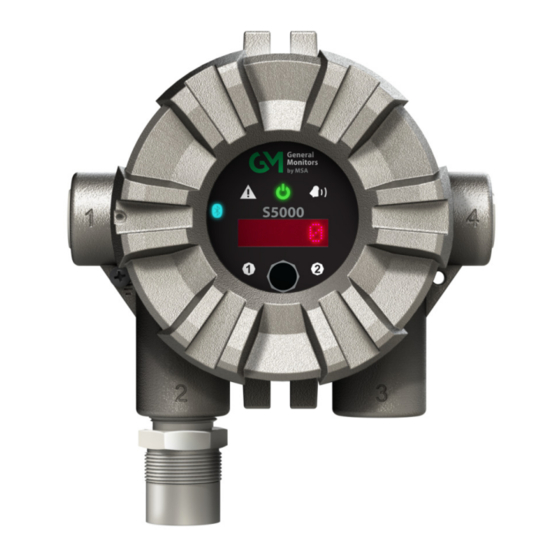
Fig. 1 S5000 Main Display In addition to the red LED display, the S5000 uses six icons to indicate status. Green LED indi- cates power supply status. A yellow triangle and red bell indicate fault and warning or alarm condi- ®... -
Page 8: No Tool Interface
Description No Tool Interface The S5000 does not require any tools or third party devices to change settings, reset alarms or perform any maintenance operation. The EZ touch button works through the glass and does not require opening the explosion proof enclosure. The EZ touch button works with bare fingers or with gloved hands, so long as the gloves are not black. -
Page 9: Dual Sensing
Description Dual Sensing The S5000 supports two Digital Sensors, or one IR400 point IR detector and one Digital Sensor simultaneously with four wire connections. However, the device will only support one passive sensor, either combustible catalytic bead or metal oxide semiconductor (MOS) sensors, based on the ATO configuration. -
Page 10: Safeswap
XCell sensors without needing to power down the instrument. Swap delay is enabled on the S5000 by default; a feature that gives users a 2 minute window to change sensors without trig- gering a fault condition. SafeSwap and Swap Delay are only applicable for XCell sensors. For more information on SafeSwap and Swap Delay, see section 6. -
Page 11: Component Overview
Description 2.10 Component Overview Fig. 3 Exploded View General Monitors S5000... -
Page 12: Label Overview
Description 2.11 Label Overview Fig. 4 Transmitter - Position of Labels Fig. 5 Board stack - Position of Labels Fig. 6 Digital Sensor - Position of Labels General Monitors S5000... - Page 13 Description Fig. 7 IR400 - Position of Labels Fig. 8 Passive Sensor - Position of Labels General Monitors S5000...
-
Page 14: Installation
Do not paint the device. Avoid painting in areas where the S5000 and remote sensor junction box are located. If painting is required in an area where an S5000 or remote sensor has been installed, exercise caution to ensure paint is not deposited on the sensor inlet fitting. Paint solvents can also cause an alarm condition to occur or potentially poison electrochemical sensors. -
Page 15: Reviewing Shipment And Identifying Product Model
Fig. 9 Shipping Label Digital and IR400 sensors are not shipped attached to the S5000. The IR400 is a one piece sensor, but all other Digital Sensors are comprised of two parts; the Sensor Body Assembly and the XCell Sensor. Sensor Body Assemblies must be installed and tightened using a strap wrench. -
Page 16: Mounting
Optimum sensor placement will depend on the surrounding processing equipment, such as pipes, valves, or turbines. MSA offers a gas and flame mapping service that systematically evaluates potential sources of leaks and recommends detector quantity and placement to create the most effective detection system. -
Page 17: Sensor Orientation
Fig. 11 shows the correct and incorrect mounting orientation for digital sensors. Passive catalytic bead and MOS sensors come already installed on the transmitter housing. Fig. 11 Correct and Incorrect Mounting Orientation for Digital Sensors General Monitors S5000... -
Page 18: Connecting Sensor To Transmitter Housing Or Remote Junction Box
If using a second sensor, connect it to the second sensor position. NOTICE If only using one sensor and it is connected to “Sensor 2” position, the S5000 will enter Sensor Missing fault. See Disable Sensor in section 4.2.2 for details on how to clear this fault. - Page 19 Connecting Sensor to the Stack and Grounding Terminal Verify the sensor connector is firmly seated on the terminal board. Attach the sensor's ground to either of the grounding screws inside the S5000 housing. Replace the display module. Push firmly on the board stack.
-
Page 20: Integrated Mounting Points
Integral Mounting Tabs (not compatible with S4000 IR400 sensors) 3.4.6 Adjustable Pipe Mount A Universal Pipe Mount Kit (Part Number 10176946) can be used to mount the S5000 on pipes ranging from 20-150 mm in diameter. Two brackets are mounted over the top of the integrated mounting tabs and fitted with an adjustable pipe band (not included). -
Page 21: Duct Mount
Consider the sensor type before choosing a duct mount location. IR400 sensors should be mounted horizontally and all other sensors should be mounted vertically. NOTICE Air flow in the duct must be zero to ensure proper calibration. Fig. 16 Flat Duct Mount Fig. 17 Round Duct Mount General Monitors S5000... -
Page 22: Mounting With A Sunshield
Installation 3.4.8 Mounting with a Sunshield A sunshield is required to protect the S5000 from direct sun light (Part Number 10180254). The sunshield can be used in any of the mounting configurations. Fig. 18 Sunshield with Surface Mount Fig. 19... -
Page 23: Installing A Remote Sensor Junction Box
316 Stainless Steel. Sensors can be remote mounted up to 100 m from the transmitter housing, as long as the S5000 transmitter is mounted within maximum distance from the power supply, as indicated in Tab. 1. -
Page 24: Electrical Power Connections
Install wiring in accordance with the electrical code of the country in use, the local authority having jurisdiction and these installation instructions, as applicable. Do not make any connections to the S5000 main board or junction box input, output, and relay connections while under power. Making connections under power could lead to electrical shock or ignition of a hazardous atmosphere. -
Page 25: Electrical Hardware Requirements
Fig. 33, or alternatively, the earth ground at the user’s power source location. An external Class 2 power supply is required to supply 12-30 VDC to the S5000. Incoming power and signal cables should be a braided shield cable such as Alpha Wire 3248 or equivalent. -
Page 26: Power Load Requirements And Maximum Mounting Distances
Consider future needs when selecting cable size and power supply. The maximum distance between the S5000 transmitter and the power supply depends on the sensor configuration (sensing technology and one or two sensors), wire gauge, and the power supply voltage. The table below outlines the maximum transmitter mounting distances. - Page 27 Maximum Mounting Distance for Local Sensors, Metric Units When sizing a system's 24 V supply, a 1 A inrush current with a 1 ms duration should be considered for each device on the power supply Assumes transmitter was ordered with relays General Monitors S5000...
- Page 28 Maximum Mounting Distance for Local and Remote Sensors, Imperial Units When sizing a system's 24 V supply, a 1 A inrush current with a 1 ms duration should be considered for each device on the power supply Assumes transmitter was ordered with relays General Monitors S5000...
- Page 29 Maximum Mounting Distance for Local and Remote Sensors, Metric Units When sizing a system's 24 V supply, a 1 A inrush current with a 1 ms duration should be considered for each device on the power supply Assumes transmitter was ordered with relays General Monitors S5000...
- Page 30 Maximum Mounting Distance for Remote Sensors, Metric Units When sizing a system's 24 V supply, a 1 A inrush current with a 1 ms duration should be considered for each device on the power supply Assumes transmitter was ordered with relays General Monitors S5000...
-
Page 31: Instructions For Power And Analog Output
(10) Attach the cable, shielding exposed, to the grounding point. (11) Replace the display module. Push firmly on the board stack where indicated. (12) Replace the S5000 cover by turning clockwise. Be sure to align threads to avoid cross- threading. - Page 32 Ensure that the electronics assembly is fully engaged in the mounting holes. If not fully seated, the touch interface performance can be negatively affected. Care must be taken to insure the S5000 inside glass surface glass is free of smudges/dirt and grease. Dirt and grease can interfere with the touch interface of the display.
-
Page 33: Relay Electrical And Power Connections
3.6.6 Relay Electrical and Power Connections Relay Board Stack Overview The S5000 can be purchased with three relays. Two of the relays can be configured for either de- energized (default) or energized and latching or non-latching. The third relay is a dedicated fault relay. - Page 34 The Fault relay state cannot be reconfigured. Relay Energy State and Terminal Connections The S5000 relay states are labeled for the default De-Energized state. The alarm/warning relay energy state can be changed on the device, which will exchange the normally open and normally closed terminals.
-
Page 35: Operation
The S5000 will remain in Start-up mode in which the fault relay is de-energized and the analog output is 3.5 mA by default. The time the S5000 stays in Start-up mode depends on the sensor. Oxygen and Carbon Monoxide sensors require a 30 minute warm-up time before being fully func- tional. -
Page 36: Startup After Power Failure
X/S Connect App. Settings The S5000 is a tool free transmitter. The infrared EZ touch button on the face of the display can be used to navigate through the menu structure. The button is designed for use with fingers with a “press”... -
Page 37: Instrument Settings
Enabled Enable/Disable Baud Rate 19200 2400-115200 BPS Modbus Format 8-n-1 Address 1-247 EZ Touch Enable/Disable Enabled Swap Delay Enabled Enabled Enable/Disable Enabled/Disabled Disabled Enable/Disable UI Password New Password Yes/No Transmitter Reset Yes/No Tab. 11 Default Device Settings General Monitors S5000... - Page 38 40.0 1.0 0-10 0-100 5 Sulfide (D22) Non-Latch Decreasing Oxygen (D16) Fine 0-25.0 %VOL 19.5 18.0 20.8 15.0 25 5-25 5-25 15 25 Non-Latch Increasing Hydrogen Fine 0-20.0 PPM 12.0 10.0 1.0 0-10 0-20 Sulfide (D24) Non-Latch General Monitors S5000...
- Page 39 Class 1 Division 2 only sensors do not have a flame arrestor (aka Frit). Course threads on the sensor assembly and sensor body are used to prevent a customer from installing into a Class 1 Division 1 sensor body. General Monitors S5000...
- Page 40 50% LEL Non-Latch (R48) IR400 Increasing Fixed at 0-100 % LEL 30 0-50 0-100 Ethylene IEC 50% LEL Non-Latch (R50) Tab. 13 IR400 Sensor Default Settings The maximum range value on catalytic bead cannot be set below 20%. General Monitors S5000...
- Page 41 0-100 (M04) 50 ppm Non-Latch Fixed at Increasing Passive MOS Fixed at 0-50 0-50 (M05) 25 ppm Non-Latch Fixed at Increasing Passive MOS Fixed at 0-20 0-20 (M06) 10 ppm Non-Latch Tab. 14 Passive Sensor Default Settings General Monitors S5000...
- Page 42 Hydrogen Sulfide 0-50.0 13.6 (D25) Hydrogen Sulfide 0-100.0 0.1 13.6 (D26) Sulfur Dioxide (D50) 0-25-0 5.28 Tab. 15 Digital Sensor Default Alarm Analog Outputs Display resolution is not a configurable option Analog Output for default range and alarms General Monitors S5000...
- Page 43 Passive CB Low 0-20% 0.10% 13.6 Range (C09, C10) Passive MOS (M04) 0-100 1 ppm 13.6 Passive MOS (M05) 0-50 1 ppm 13.6 Passive MOS (M06) 0-20 1 ppm 13.6 Tab. 17 Passive Sensor Default Alarm Analog Outputs General Monitors S5000...
-
Page 44: Sensor Setup
0 mA. By default, the S5000 has the Sensor 2 position disabled. If at any time a sensor is connected to a position that is disabled, the device will automatically enable that sensor position. - Page 45 When the desired value is displayed, wait until Latching option appears. To change warning to latching or non-latching, touch button when the option is displayed. Touch button when “Finished?” is displayed to exit. General Monitors S5000...
-
Page 46: Relay Settings
If setting is changed, touch button when “Finished?” is displayed to save the change and move on to next setup. If no change is made, the menu will move on to next setup after two screen scroll rotation. General Monitors S5000... - Page 47 Common Mode Relay Map and Alarm Actuation Discrete mode allows a separate action for each sensor. Relay 1 is actuated by Sensor 1 alarms and Relay 2 is actuated by Sensor 2 alarms Fig. 28 Discrete Mode Relay Map and Alarm Actuation General Monitors S5000...
-
Page 48: Hart Settings
Touch button when HART AO Setup is displayed. The current HART analog output signal is displayed. To change the HART output signal, touch button to change to either 1.25 or 3.5. Touch button when "Finished?" is displayed to exit. General Monitors S5000... -
Page 49: Bluetooth
X/S Connect App. The S5000 blue LED in the middle left of the display will flash when a device is paired with it as a visual indication of the pairing. Once paired with an S5000, the user will be able to connect to the same S5000 remotely and without a password, unless over 25 other devices are paired with the same S5000 afterwards. -
Page 50: Modbus Settings
Address will scroll across display followed by the current Address setting. Hold finger on button to scroll quickly through values or touch button repeatedly to move through values more slowly. Address options range from 1-247. Touch button when “Finished?” is displayed to exit. General Monitors S5000... -
Page 51: Ez Touch Button
After the sensor countdown is complete, the analog output will return to reporting a live gas reading. If a sensor is not reconnected after the 2 minute window, the S5000 will enter a fault condition. All XCell Sensors have Swap Delay and do not need to be disconnected from power while changing sensors. -
Page 52: Transmitter Setting Reset
During transmitter reset, the analog output displays 1.25 mA. NOTICE Verify all sensor settings (calibration level and alarm values) after resetting transmitter. Sensors may require recalibration to clear a fault after resetting transmitter. General Monitors S5000... -
Page 53: Info Menu - Viewing Device Status
Each of the last 10 faults will scroll across the screen twice. At the end of the fault log, menu goes back to Info menu options. The user will not be asked to exit with “Finished?” at the end of this menu. General Monitors S5000... -
Page 54: Device Tag
Fair condition occurs when the current calibrated span sensitivity is less than 50% of the way from the initial calibration sensitivity and the end of life span sensitivity. NOTICE Using expired calibration gas or the incorrect calibration gas can result in a premature "Fair" status. General Monitors S5000... -
Page 55: Setting Only Configurable Via Bluetooth , Modbus, Or Hart
Alarm Enable/Disable 4.4.1 AO Custom Levels S5000 offers three factory defined analog outputs (AO) level sets, i.e., 0 mA with HART disabled, or 3.5 mA and 1.25 mA with HART enabled. Users can also specify their own custom AO levels for each transmitter mode. -
Page 56: Alarm Direction
WARNING! Use zero gas when zeroing the S5000 transmitter if there is any possibility of background gas. Otherwise, improper calibration could occur. For optimal sensor performance, allow sensor to acclimate to application conditions for 24 hours before performing an initial calibration. -
Page 57: Calibration Frequency
For this, record the "as found" and "as left" values and track the percent adjustment over time. Then, gradually extend calibration intervals until the percent adjustment is greater than the expected accuracy of the sensor. General Monitors S5000... -
Page 58: Calibration Frequency For Xcell Sensors With Trucal (H 2 S & Co Only)
Fig. 30 Calibration Curve The Sensor Span Value (i.e. Cal Level) in the device menu should be the same as the concentra- tion listed on the calibration gas cylinder. General Monitors S5000... -
Page 59: How To Zero Calibrate Xcell And Ir400 Sensors
The green Calibration Cap must be removed from the sensor after a zero calibration. Failure to do so could restrict gas flow to the sensor and result in erroneously low readings. Failure to follow the above warning can result in serious personal injury or loss of life. General Monitors S5000... -
Page 60: How To Calibrate Xcell Sensors
The green Calibration Cap must be removed from the sensor after calibration. Failure to do so could restrict gas flow to the sensor and result in erroneously low readings. Failure to follow the above warning can result in serious personal injury or loss of life. General Monitors S5000... -
Page 61: How To Calibrate An Oxygen Xcell Sensor
Once the Zero Calibration is complete, remove the tubing from the sensor guard inlet. (10) The display will show “Apply Gas”. Attach tubing for calibration gas and turn on the regulator. (11) Display will show “Calibration in Progress”. (12) “Calibration Complete. Remove Gas” will show when span is complete. General Monitors S5000... -
Page 62: Xcell Catalytic Bead Failsafe
Failure to follow the above warning can result in serious personal injury or loss of life. 5.11 Calibration Confirmation The S5000 Series Monitor records the date of the last successful calibration. This date can then be displayed via the Status Menu. -
Page 63: Ir400 Cleaning Procedure
The device will go into a “Cleaning required” fault with an analog output of 2.0 mA when cleaning is needed. The S5000 analog output may go down to 1.25 mA while the optical path is blocked, and display will indicate “Beam Block”. -
Page 64: Replacing An Xcell Sensor
Maintenance Replacing an XCell Sensor The only routine maintenance item is the sensor, which has a limited lifetime. The S5000 sensors with TruCal technology will indicate when the sensor is near end of life through the Status Menu. When the Sensor Life & Health status is "Fair", there is approximately 2 month time frame to replace the sensor before it will no longer function. - Page 65 The S5000 Gas Monitor is shipped with the Sensor Swap Delay enabled. IF enabled, the 4-20 mA output signal goes to 3.5 mA and the FAULT relay will hold off a fault indication for 2 minutes. This setting allows the operator to exchange sensor modules without a FAULT indication.
-
Page 66: Replacing A Passive Sensor (Cat Bead Or Mos)
Unscrew the lid. Remove the User Interface Module. Refer to the sensor wiring diagram label inside the S5000 transmitter to locate the sensor connector and unplug it from the transmitter. Unscrew the sensor head until it is totally off. Guide the sensor wires so they will not get caught by the internal parts of the S5000 while sensor head is turning. -
Page 67: Troubleshooting
This fault occurs if the supply Ensure that the supply voltage is voltage at the S5000 is below F001 Low Supply Voltage Non-Latch within the range of 12-30 VDC at the +10.5 VDC or higher than... - Page 68 Cycle the power to the unit. If F007 Invalid Sensor Config- Latch sensor channel configuration the fault persists, the unit must be uration Fault is invalid. returned to the factory or authorized service center for repair. General Monitors S5000...
- Page 69 Use the "Reset" entry in UI menu to 113/F213 Full Span Calibra- This fault occurs when last full reset the fault. Re-calibrate the sensor Latch tion Failed Fault span calibration has failed will also clear the fault. Replace the sensor if this fault persists. General Monitors S5000...
- Page 70 F118/F218 Analog Output 250 ohm load resistor installed. The Non-Latch 20 mA analog output loop is Mismatch Fault fault will be cleared automatically malfunctioning. once the loop is closed and wires are properly connected. Tab. 21 Troubleshooting General Monitors S5000...
-
Page 71: Ordering Information
Repair or alteration of the S5000 Gas Monitor, beyond the scope of the maintenance procedures provided in this manual or by anyone other than authorized MSA service personnel, could cause the product to fail to perform as designed and persons who rely on this product for their safety could sustain serious personal injury or loss of life. - Page 72 (12"-20" / 305-508 mm diameter) Duct mount kit, round, large, 10179324 (20"-40" / 508-1016 mm diameter) Calibration Kit (XCell) CALKIT1 Pipe Mount Kit, Universal Pipe Mount, X5000/S5000 10176946 Junction Box, SST, IIB + H2 324240-1 Junction Box Junction Box, SST, IIC...
-
Page 73: Appendix: Specifications
6.0 W 4.8 W Single Sensor Power: 4.3 W 4.3 W 8.4 W Dual Sensing Tab. 23 Digital Sensor Specifications not guaranteed for extended temperature range S5000 transmitter has an operating temperature range of -55°C to +75°C General Monitors S5000... - Page 74 Transmitters purchased with passive sensors are not capable of dual sensing and Power: cannot be changed to any other sensor type than the one with which it was originally Dual Sensing purchase. Tab. 24 Passive Sensor Specifications not guaranteed for extended temperature range General Monitors S5000...
- Page 75 Appendix: Specifications Fig. 33 Housing Dimensions Material Weight 7.30 lbs 316 Stainless Steel 7.92 lbs w/ relays Tab. 25 Housing Material Specifications General Monitors S5000...
-
Page 76: Appendix: General Certification Information
Appendix: General Certification Information Appendix: General Certification Information The S5000 Transmitter, S5000 Junction Box and Digital Sensor have the following certifications/ approvals: ATEX, IECEx, CSA, INMETRO, DNV·GL Type Approval. They also comply to the EMC, Radio Equipment and Marine Equipment Directives. - Page 77 Digital Sensor for Div 1 & 2, Zone 1 & 2 (Left) vs Digital Sensor for Div 2, Zone 2 only (right) IR400 See the IR400 instruction manual, P/N MANIR400 or certificates Sira 07ATEX1253 and IECEx SIR 07.0080. Passive Sensors See certificates Sira 00ATEX1039U and IECEx SIR 07.0007U. General Monitors S5000...
- Page 78 Sealing requirements: - Aluminum S5000 transmitter and Junction Box: A seal shall be installed within 18 in (450 mm) of the enclosure. - Stainless Steel S5000 transmitter and Junction Box: Seal is not required. Transmitter and Junction Box (cemented or non-cemented covers) - do not open when ener- ...
- Page 79 For combustible gas detection performance applications, the appropriate Digital Sensor model number shall only be used to construct the S5000 Gas Monitor fixed gas detection system; mounted onto either the S5000 transmitter or S5000 Junction Box enclosures and receive power and control from the transmitter.
-
Page 80: Appendix: Hart Specific Information
Appendix: HART Specific Information Appendix: HART Specific Information The S5000 Gas Monitor is available with an optional HART (Highway Addressable Remote Trans- ducer) output communications protocol. With this option, the S5000 complies with HART Protocol Revision 7 and uses the 16-bit manufacturer and device codes. This document specifies all the device specific features and documents HART Protocol implementation details (e.g., the Engi-... - Page 81 Appendix: HART Specific Information General Monitors S5000...
- Page 82 Appendix: HART Specific Information General Monitors S5000...
- Page 83 Appendix: HART Specific Information General Monitors S5000...
- Page 84 For local MSA contacts, please visit us at MSAsafety.com Because every life has a purpose...
Need help?
Do you have a question about the S5000 and is the answer not in the manual?
Questions and answers