Table of Contents
Advertisement
Apator SA, ul. Gdańska 4a lok. C4, 87-100 Toruń, Poland
e-mail: apator@apator.com, www.apator.com
Sales:
Apator Powogaz SA, ul. K. Janickiego 23/25, 60-542 Poznań, Poland
e-mail: handel.powogaz@apator.com
tel. +48 61 8418 133, 136, 138, 148
Compact Heat Meter
ELF
Technical description
For firmware versions 13.01 or higher
ISO 9001
PN-N-18001
ISO 14001
Advertisement
Table of Contents

Related Manuals for Apator ELF


Summary of Contents for Apator ELF
- Page 1 Apator SA, ul. Gdańska 4a lok. C4, 87-100 Toruń, Poland e-mail: apator@apator.com, www.apator.com Sales: Apator Powogaz SA, ul. K. Janickiego 23/25, 60-542 Poznań, Poland e-mail: handel.powogaz@apator.com tel. +48 61 8418 133, 136, 138, 148 Compact Heat Meter Technical description For firmware versions 13.01 or higher...
- Page 2 - 2 -...
-
Page 3: Table Of Contents
Contents 1. Subject ..............................4 2. Regulatory and standard compliance.....................4 3. Design, functional description & basic characteristics ................4 4. Basic specifications ..........................5 5. Data types ..............................8 5.1. Actual data ............................8 5.1.1. Heat consumption ..........................8 5.1.2. Water volume ............................8 5.1.3. Supply and return temperatures; differential temperature .............9 5.1.4. -
Page 4: Subject
Elf heat meters are compatible with remote reading interfaces and with up to four additional devices (e.g. a water meter or a gas meter) equipped with pulsers. The interfaces available are: one Wireless M-Bus,... -
Page 5: Basic Specifications
The calculation formula is: ∫ t dV − Q - quantity of consumed heat dV - volume of flowing water k - temperature coefficient of water t1 - supply water temperature t2 - return water temperature Another value, which is called the resolver metrological test, is calculated to evaluate the metrological class of the electronic system as a stand-alone resolver for the heat meter. - Page 6 Flow transducer Manufacturer mark – APATOR POWOGAZ S.A. JS90-0,6 JS90-1 JS90-1,5 JS90-1,5 JS90-2,5 Factory mark – -G1-NI Nominal diameter – Minimum volume flow – horizontal arrangement H Minimum volume flow – vertical arrangement V Nominal volume flow Maximum volume flow...
- Page 7 Electronic resolver Manufacturer mark – APATOR POWOGAZ S.A. Energy unit, selectable – GJ, kWh or Gcal Display type – LCD, 7 digits, height: 7 mm Type of resolver fastening to water end – Rotary – revolution angle 0 to 360°...
-
Page 8: Data Types
Temperature sensor pair Manufacturer mark – APATOR POWOGAZ S.A. Thermometer resistor – Pt 500 (TOPE42) Method of connection with the resolver – soldered Θ = 0 °C Θ Temperature measurement range °C = 105 °C Θ = 3 °C Θ... -
Page 9: Supply And Return Temperatures; Differential Temperature
M-Bus frames. Only low frequency signals are used; however, it is possible to order custom interfaces of any type which will convert the signals to compatible pulses. Only the interfaces from Apator-Powogaz shall be used, since they ensure proper interference protection of pulse inputs. -
Page 10: Real And Working Time
• 8 – supply temperature sensor damaged or temperature outside of range; • 16 – temperature sensors interchanged or negative differential temperature; indicated if |∆T| > 0.3°C, the error is saved to archive data if |∆T| > differential temperature insensibility value; •... -
Page 11: Calibration, Configuration And Service Data
- non-standard working time – time calculated in case of errors: 2, 4, 8, 16, 32 1024, - standard working time – time calculated in all other cases; no error is raised or errors: 1, 64, 128, 256 or 512 are raised. 5.2. -
Page 12: Archive Data
5.3. Archive data Archiving of the heat meter data is fully configurable by the user with the ElfSerwis configuration softwa- re (see the detailed description in the separate document). A space intended for archived data can be divided in any way between 4 types of archives, archive for cycle 1, archive for cycle 2, monthly archive and annual archive. -
Page 13: Monthly And Annual Cycle Record
CRC for the data Total 5.3.3. Emergency (failure) state archive record Furthermore, Elf heat meters are provided with archive for emergency states. A space intended for this archive is permanent and its volume cannot be configured, as opposed to periodic archives. Data type Size in bytes Record number –... -
Page 14: Heat Meter Operating Guide. Lcd
If the readings need to be displayed or configured remotely, use the software, interfaces and other tools from Apator-Powogaz and follow the manuals enclosed with these products. The display of data on Elf heat meters is divided into five menu groups which correspond to the func- tionality of the data: •... - Page 15 The displayed number depends on the user configuration. If "0" is configured for the given group, the group is disabled from recording. This reading is followed by a cycled display of successive values in the record; at the beginning of each record shows a message which record will be displayed at the given moment and how many records have been registered, e.g.
-
Page 16: Metrological Test
7. REMOTE READING OF DATA Elf heat meters feature a connector for communication interfaces which enable remote reading and wri- ting of data. The connector also enables connection of pulse signals with additional pulse inputs, and to output the pulses generated by the heat meter to one of the output interfaces. Only interfaces from Apator-Powogaz shall be used, since they ensure proper support of the heat meter. -
Page 17: Wired M-Bus Interfaces And Pulse I/O Interfaces
Wired M-Bus interfaces are available for connecting of up to four additional pulse inputs and with one pulse output, the pulse I/O interfaces with a maximum of four auxiliary pulse inputs and one pulse output, a Wireless M-Bus interface, and an USB interface. Interface M-Bus Pulse OUT... -
Page 18: Interface Connection Diagram
Note on readout frequency and default transmission settings: Transmission of data from Elf increases consumption of the battery power. If readout frequency is higher 15 minutes, the battery life may be shorter. This applies only for the default baud rate of 2400;... -
Page 19: Interface Technical Parameters
Version 1: M-BUS + 4 pulse IN Version 2: M-BUS + 2 pulse IN + 1 pulse OUT M-BUS M-BUS M-Bus M-Bus M-Bus Slave Master Master Version 3: 4 pulse IN Version 4: 3 pulse IN + 1 pulse OUT NC NC M IN3 NC NC... -
Page 20: Operating Principle Of The M-Bus Communication Interface
Pulse input (dry contact, NO, open collector, open drain) Maximum voltage Maximum current 0,05 Wire insulation voltage rating > 500 Maximum wire length Maximum no. of inputs 4 (2) Max frequency of input pulse Input pulse duration Input pulse interval Maximum cross section of supply wires mm²... -
Page 21: Wireless Interface
Note: The pulses are output though the CMOS gate. Proper performance requires galvanically separa- ted interfaces from Apator-Powogaz. Operating the pulse output in the test (fast) mode the ma- ximum frequency of which is 64 Hz, will significantly increase the battery power consumption. If this operating mode is continuous, the battery life is reduced to approx. -
Page 22: Usb Interface
7.3. USB interface The USB communication interface enables quick and easy readouts of data from the meter, and to configu- re the available parameters. The main advantage here is that the interface requires no additional transmis- sion converters. See the separate operating manual for the instructions for driver installation and commu- nication software setup. -
Page 23: Sealing
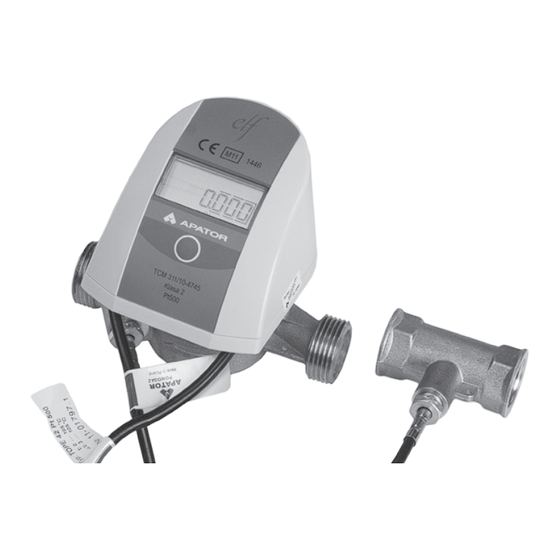
3. Before installing the temperature sensor in a tee joint or a valve, check that the temperature sensor fitting meets the requirements for the sensor seat depth and that the seat diameter matches the sensor diameter. See the dimensions in Fig. 1 and 2. Temperature sensor Sealing ring Tee joint... -
Page 24: Electrical Interference
8.1. Sealing Elf heat meters are sealed with self-adhesive seals to prevent unauthorised access to the electronic circuit – see the figure below. The enclosure base is sealed together with the enclosure with a sealing wire threaded through the holes in the band clip. -
Page 25: Warranty And Service
• installation or operation considered as unintented use in the user manual; • mechanical damage to the resolver enclosure. Elf heat meters self-diagnose by indication of error codes. Specific error codes are only displayed during an emergency/failure; if the error signal cause is removed, the error signal will be automatically reset. -
Page 26: Marking And Ordering Guideline
Basic MID design, label in Hungarian ........Design for Russia Design for MessTechnik Design for Ukraine Design for GranSystema Belarus ........Design Example order code: 65-0045107-000 - Elf return, GJ, qP = 0.6 m /h, DN15, no interface, Basic MID version - 26 -... -
Page 27: Ordering The Communication Modules
0949-500-090 Elf interface enclosure, empty 0949-500-091 Elf MBUS interface + 4 pulse inputs 0949-500-092 Elf MBUS interface + 2 pulse inputs + 1 pulse output 0949-500-093 Elf MBUS interface + 4 pulse inputs 0949-500-094 Elf MBUS interface + 3 pulse inputs + 1 pulse output... -
Page 28: Annexes
11. ANNEXES LCD test Annex A. Display in the basic operating mode. Current date Current time Operating time Error operating time Heat meter on supply Calibration pulse constant Pulse constant 1 Legend Heat consumption - permanent Depress and hold Short depress Pulse constant 2 LCD test Automatic... - Page 29 Annex B. Display of data recorded in cycle 3 and 4. Registration time Registration date The data cycles automatically every 2 seconds. Pressing the push-button switches to the next Heat consumption registration display Water volume Operating time Error operating time Pulse Input 1 Pulse Input 2 Pulse Input 3...
- Page 30 - 30 -...
- Page 31 - 31 -...
- Page 32 ENVIRONMENTAL NOTICE Do not dispose of with regular waste/trash. Bring the product to a specialist collection point for disposal. You will help protect the natural environment.
Need help?
Do you have a question about the ELF and is the answer not in the manual?
Questions and answers