Table of Contents
Advertisement
Quick Links
Installation commissioning and servicing instructions
Wall hung RSF gas fired condensing system boiler
Greenstar i System
For sealed central heating systems and indirect mains fed domestic hot water
ErP
These appliances are for use with:
Natural Gas or L.P.G.
(Cat. II 2H 3P type C13, C33 & C53)
Natural Gas
L.P.G.
If you smell gas:
▶ Well away from the building: call the National Gas Emergency
Service on 0800 111 999.
▶ L.P.G. boilers: Call the supplier's number on the side of the gas
tank.
UK/IE
Model
GC Number
Greenstar 9i System
41-406-21
ErP
Greenstar12i System
ErP
41-406-23
Greenstar 15i System
ErP
41-406-25
Greenstar 18i System
ErP
41-406-27
Greenstar 21i System
41-406-29
ErP
Greenstar 24i System
ErP
41-406-31
Greenstar 9i System
ErP
41-406-22
Greenstar12i System
ErP
41-406-24
Greenstar 15i System
41-406-26
ErP
Greenstar 18i System
41-406-28
ErP
Greenstar 21i System
ErP
41-406-30
Greenstar 24i System
ErP
41-406-32
Advertisement
Table of Contents

Related Manuals for Worcester Greenstar i System ErP Series


Summary of Contents for Worcester Greenstar i System ErP Series
- Page 1 Installation commissioning and servicing instructions Wall hung RSF gas fired condensing system boiler Greenstar i System For sealed central heating systems and indirect mains fed domestic hot water These appliances are for use with: Natural Gas or L.P.G. (Cat. II 2H 3P type C13, C33 & C53) Model GC Number Natural Gas...
-
Page 2: Table Of Contents
Contents Contents Key to symbols and safety instructions ....4 Commissioning ........36 Key to symbols . - Page 3 Contents 7.7.9 Exhaust assembly removal ..... . 58 7.7.10 Heat exchanger removal ......58 7.7.11 Re-assembly of the air/gas manifold clamping plate .
-
Page 4: Key To Symbols And Safety Instructions
If you are in any doubt, contact the Worcester Technical helpline (0330 123 3366). a list entry Please leave these instructions with the completed BENCHMARK... -
Page 5: Safety Precautions
▶ Turn off the gas at the meter or regulator. ▶ Open windows and doors. ▶ Warn your neighbours and leave the building. Only use the approved Worcester Condensfit II flue system with this ▶ Prevent anyone from entering the building. appliance. -
Page 6: Regulations
Regulations Regulations Installation regulations Current Gas Safety (Installation & Use) Regulations: All gas appliances must be installed by a competent person in accordance with the above regulations. Failure to install appliances correctly could lead to prosecution. The appliance must be installed in accordance with, and comply to, the current: Gas Safety Regulations, IET Regulations, Building Regulations, Building Standards (Scotland) (Consolidation), Building Regulations (Northern Ireland), local water by-laws, Health &... -
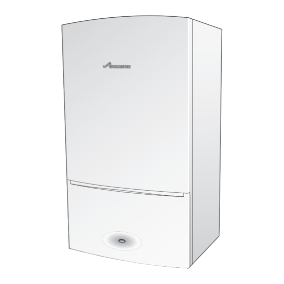
Page 7: Appliance Information
Appliance information Appliance information Appliance * 7 1 0 m m t o t o p o f c a s e f r o n t 4 0 0 m m Fig. 1 Standard package Wall hung gas-fired condensing system appliance for central heating and domestic hot water. -
Page 8: Technical Data
Appliance information Technical data Natural Gas technical data Natural gas DESCRIPTION UNIT 12kW 15kW 18kW 21kW 24kW Gas flow rate - Max. 10 minutes from lighting Natural Gas G20 m³/h 0.974 1.298 1.626 1.952 2.282 2.607 Gas injector diameter Central Heating Maximum rated heat input (net) 12.27 15.37... - Page 9 Appliance information L.P.G. technical data L.P.G. DESCRIPTION UNIT 12kW 15kW 18kW 21kW 24kW Gas flow rate - Max. 10 minutes from lighting Propane Gas (L.P.G.) kg/h 0.72 0.95 1.19 1.43 1.68 1.91 Gas injector diameter 3.95 3.95 Central Heating Maximum rated heat input (net) 12.27 15.37 18.44...
-
Page 10: Energy Efficiency
Appliance information Energy efficiency Natural Gas appliances The following product data satisfy the requirements of the EU Regulations No. 811/2013 and No. 812/2013 supplementing Directive 2010/30/EU. Product data Symbol Unit 7733600011 7733600010 7733600009 7733600008 7733600007 7733600006 Product type – – 9i System 12i System 15i System... - Page 11 Appliance information LPG appliances The following product data satisfy the requirements of the EU Regulations No. 811/2013 and No. 812/2013 supplementing Directive 2010/30/EU. Product data Symbol Unit 7733600033 7733600034 7733600035 7733600036 7733600037 7733600038 Product type – – 9i System 12i System 15i System 18i System 21i System...
-
Page 12: Layout
Appliance information Layout Fig. 2 Main appliance components Greenstar i System - 6 720 806 945 (2015/07) - Page 13 • Standard wall frame provides vertical pipe route behind the appliance • Compatible with all Worcester standard and intelligent controls • Condensfit II flue systems 60/100 and 80/125 mm allows plume re-direction as standard and ability to attach plume management kits •...
-
Page 14: Electrical Diagram
Appliance information 3.4.1 Electrical diagram White White White Orange Blue Orange Violet Black White Orange Black Brown Blue 6720806945-10.1Wo Fig. 3 Electrical diagram Greenstar i System - 6 720 806 945 (2015/07) - Page 15 Low voltage switch (NOT USED) External control system with EMS bus control (connection for Worcester intelligent wall mounted controls when using integral diverter valve kit) Table 9 Electrical connections 1) Green plug in connector pack found under installer connections cover.
-
Page 16: Pre-Installation
▶ In cases where all attempts to find a micro leak have failed, Worcester, Bosch Group supports the use of Fernox F4 leak sealer. NOTICE: Risk of damage to appliance or accessories! ▶... -
Page 17: Water Systems And Pipe Work
Pre-installation Water systems and pipe work Example installation (S-Plan) Plastic pipework: NOTICE: Two port valves • Any plastic pipe work must have a polymeric barrier with 600mm ▶ An automatic bypass valve is required when fitting an (minimum) length of copper pipe connected to the appliance. S-plan type system with two-port valves. -
Page 18: Available Pump Head
Pre-installation 4.3.1 Available pump head Appliance location and clearances In order to save as much energy as possible and the 4.4.1 Installation minimise the possibility of water circulation noise, a low This appliance is only suitable for installing internally within a property at characteristic should be chosen. -
Page 19: Bathrooms
Pre-installation 4.4.4 Bathrooms Pressure relief pipe work Please check the IP rating of any control to be used on this appliance. WARNING: Risk of scalding! Only certain controls can be fitted when the appliance is inside of the Injury if discharge pipe is not routed correctly. shaded area. -
Page 20: Condensate Discharge
Pre-installation Condensate discharge 4.6.3 Internal connections In order to minimise risk of freezing during prolonged cold spells, the 4.6.1 Appliance siphonic condensate trap following methods of installing condensate drainage pipe should be The appliance has a large capacity siphonic condensate trap reducing adopted, in order of priority. -
Page 21: External Connections
Pre-installation ▶ The pipe should be run internally as far as possible before going Condensate pump externally and the pipe diameter should be increased to 32mm Where “gravity discharge” to an internal termination is not physically before it passes through the wall to the exterior. possible, or where very long internal runs would be required to reach a ▶... -
Page 22: Standard Accessories
Pre-installation Integral diveter valve option The appliance has the option to fit an integral diverter valve kit, which has multiple controls options for the use with vented and unvented hot water cylinders. The details can be found in the Installation Instructions for the diverter valve kit. -
Page 23: Plumbing Manifold
Plume management kits are available for the 60/100 horizontal flue system. ▶ Only use the approved Worcester Condensfit II flue system with this appliance. Effective flue lengths: ▶ Each 90° bend used is equivalent to 2 metres of straight flue. -
Page 24: Flue Lengths
Pre-installation 4.9.1 Flue lengths Horizontal flue with additional elbow (1 x 90 ° bend) The flue systems have different maximum flue lengths The Greenstar series has the option of two horizontal 60/100 RSF (telescopic and longer telescopic) and one horizontal 80/125 RSF (telescopic) flue system and two vertical RSF (60/100 or 80/125) flue systems: Refer to the following example Flue options for the maximum flue... - Page 25 Pre-installation High level horizontal flue with additional elbows Vertical balanced flue with elbow offset (2 x 90 ° bends) Maximum flue length (mm) Maximum flue length 60/100 80/125 (mm) High level horizontal flue with 2 x 90° bends 2,600 11,000 60/100 80/125 Vertical balanced flue with 2 x 90°...
-
Page 26: Determine The Plume Management System Length
Pre-installation 4.9.2 Determine the plume management system length Minimum plume management length The minimum plume length should be calculated to ensure that the air Note: Measurement M plume length inlet and exhaust have a minimum distance of 500mm between them ▶... -
Page 27: Flue Terminal Positions
Pre-installation 4.10 Flue terminal positions All measurements in millimetres 52mm 104mm 1,500 1,500 300 300 300 300 1,200 Boundary Line Fig. 22 Flue terminal positions NOTICE: ▶ All measurements are the minimum clearances required. ▶ Terminals must be positioned so to avoid combustion products entering the building. ▶... -
Page 28: Plume Management Terminal Positions
Pre-installation 4.11 Plume management terminal positions All measurements in millimetres Flue terminal guard 7 716 191 176 ±45° Plume re-direction: 180° Flue Exhaust Outlet 1,500 Air Intake ±80° 1,200 Boundary Line Fig. 23 Plume terminal positions Maximum and minimum plume management lengths: ▶... -
Page 29: Installation
Installation Wall mounting template & flue openings Installation WARNING: Damage to property! Damage caused by drilling into pipes, electrical cables, NOTICE: Risk of damage to appliance or accessories. damp proof course or other hazards. ▶ All the previous pre-installation sections must be ▶... -
Page 30: Appliance Connections
Installation 1 3 3 m m 25mm Fig. 25 Condensate drain pipe work detail Preparing the wallframe The bonded washer supplied is for the Gas connection only. ▶ Fit sealing washers to service valves before hanging appliance. Fig. 24 Marking the flue position Fixing the wall mounting frame ▶... -
Page 31: Front Panel Removal
Installation 5.3.1 Front panel removal 5.3.3 Pressure relief connections ▶ Removing outer case NOTICE: The pressure relief connector must be – Undo and remove the two outer screws [1] securing the repositioned after the appliance has been correctly appliance casing to release the bottom of the front panel. mounted to the wall mounting frame refer to figure 30. -
Page 32: Reconnecting The Siphon
Installation Siphon removal Refer to figure 32 ▶ Remove the siphon securing screw [1] completely. ▶ Rotate the siphon [3] level and to the right (until the upper arm [2]is parallel to the side casing), to release from the bayonet connection. ▶... -
Page 33: Flue Turret/Adaptor Installation
Installation ▶ Align the flue turret/vertical adaptor to the appliance flue outlet with Flue turret/adaptor installation flat facing [3] to the rear of the appliance. If replacing a Greenstar i Junior (2005-2015) or a The flue turret/adaptor should be pushed straight down, on to the Greenstar Si (2005-2013), the same rear exit flue hole appliance. -
Page 34: Electrical
[3]. All Worcester twin channel digital controls provide this functionality. – The low voltage connectors are contained in a bag inside the connections cover (it is advised to fit the edge connectors even if there are not used). -
Page 35: External Controls (Wiring Centre) - Domestic
& connection. See optional diverter valve kit instructions for full details. This kit also allows for the Worcester plug-in controls options to be used, which details can be found in the diver valve kit instructions. -
Page 36: Commissioning
▶ In cases where all attempts to find a micro leak have ▶ Manually vent all radiators, tighten when completed and check the failed, Worcester, Bosch Group supports the use of system and correct any leaks. Fernox F4 leak sealer. -
Page 37: Starting The Appliance
Commissioning Starting the appliance 6.4.1 Appliance start up screens On initial start up, the following screens are displayed: CAUTION: Running the appliance 1. All the symbols are displayed for approximately two seconds. ▶ Never run the appliance when the appliance/system 2. -
Page 38: Info Menu And Operational Status Codes
Commissioning Available menus SCREEN DISPLAY DESCRIPTION Text line display Description All possible screen symbols This screen is displayed briefly during appliance start up and shows Various info (Info Menu) Information from current status to all the symbols that could be appliance and component output displayed. - Page 39 Commissioning Info menu listing Operational status codes listing Info menu No. Description Status code Description Current status CH system is being heated. DHW cylinder system is being heated (only available • Appliance current operating status (see table 33 when using the optional integral diverter valve kit). for operational status codes).
-
Page 40: Commissioning
▶ The gas valve is factory set and must not be adjusted during commissioning if found to be out of tolerance, • 2.5 mbar for Natural Gas please contact Worcester, Bosch Group. • 4 mbar for L.P.G. Natural gas When running in the service mode, the appliance will... -
Page 41: Checking The Gas Rate
Commissioning 6.5.3 Checking the gas rate ▶ The gas rate should be measured at the gas meter after the appliance has been operating for a minimum of 10 minutes at maximum output. ▶ See Technical data section on page 8 of this manual for gas rates and CO/CO ratios. -
Page 42: Co And Combustion Checks
▶ The gas valve is factory set and must not be adjusted during commissioning if found to be out of tolerance, please contact the Worcester, Bosch Group help line 0330 123 3366. Zero the analyser START Set boiler to ≥... -
Page 43: Checking Flue Integrity
Commissioning 6.5.8 Checking flue integrity Setting appliance to maximum The appliance case must be fitted whilst this test is Maximum output mode carried out. ▶ The diverter valve will go to mid position in chimney sweep mode. A hot water outlet can be opened to prevent the appliance from shutting down due to high temperature during testing. -
Page 44: Service Reminder Function
– 1 - 72 = Number of months till reminder The appliance will auto-detect the connection of a Worcester outdoor sensor which will enable basic weather compensation with the settings Table 36 Service reminder time - 2.5F from boiler settings menu controlled from the appliance. -
Page 45: Boiler Settings Menu
Commissioning ▶ Using the DHW up/down arrow buttons to scroll through to the Boiler settings Menu list Description Weather Sensor settings menu. 2.1b - Max. DHW power Only available when optional integral ▶ Select menu item 5.W1 - WDM mode enable using the button. -
Page 46: Master Settings Menu
Commissioning 6.5.14 Master settings menu Finishing commissioning The Master settings menu allows for the adjustment boundaries to be 6.6.1 Replace front panel: set. These will set limits for the actual values that can be set in the Boiler ▶ Replace front panel making sure that the securing points are properly settings menu. -
Page 47: Installing Bottom Panel
Commissioning 6.6.3 Installing bottom panel Economic central heating temperature ▶ The bottom panel slides onto two ledges [1] either side of the The economic value sets the maximum flow temperature to the most appliance frame. efficient operation of the appliance. ▶... -
Page 48: Optional Integral Diver Valve Kit Fitted: Eco/Preheat Mode Activation
▶ Show the customer how to safely isolate the appliance. ▶ Advise the customer where they can find information on the Worcester, Bosch Group website www.worcester-bosch.co.uk. ▶ Advise the customer that the varying external temperatures will Preheat affect the output of the appliance, especially the DHW. -
Page 49: Appliance Guarantee
Inspection and service – Please send your completed form to: ▶ Check that the terminal and terminal guard, if fitted, are Worcester, Bosch Group, Cotswold Way, Warndon, Worcester, unobstructed and undamaged. WR4 9SW. ▶ If the appliance is in a compartment or cupboard, check that the To read the full Terms &... -
Page 50: Test Menu
Service and spares 7.1.2 Test menu Component access The Test menu function allows some components operation to be ▶ Remove the bottom panel checked, table 42 for details. – Pull the catch down. – Slide the panel forward and down to remove. ▶... -
Page 51: Fan Pressure Test
▶ Re-check the fan pressure readings. If the appliance, after completing the above checks, fails the fan pressure test then contact Worcester, Bosch Group for advice. ▶ After the measurements are taken switch the appliance off. ▶ Disconnect the manometer and replace the test point cover. -
Page 52: Flue Gas Analysis
Service and spares Flue gas analysis Cleaning the siphon and heat exchanger NOTICE: Combustion testing NOTICE: Gaskets ▶ Combustion testing must be carried out by a ▶ The burner and electrode assembly gaskets must be competent person. Testing must not be attempted replaced if the air/gas manifold clamping plate is unless the person carrying out the combustion check loosened or removed. -
Page 53: Refitting The Siphon After Cleaning
Service and spares Removing the siphon 7.6.2 Refitting the siphon after cleaning ▶ Place a suitable container under the siphon and remove the cap to ▶ Fill siphon with 200 to 250 millilitres of water. drain the siphon, replace the cap once drained. ▶... -
Page 54: Cleaning The Primary Heat Exchanger
Service and spares 7.6.4 Cleaning the primary heat exchanger Refer to figure 68. ▶ It is recommended that all channels are cleaned. ▶ Remove the siphon and place a suitable container under the outlet to catch the water and debris. ▶... -
Page 55: Replacement Of Parts
Service and spares Replacement of parts 7.7.2 Siphon removal replacement of parts CAUTION: Mains supplies: Access to the siphon ▶ Turn off the gas supply and isolate the mains supplies Refer to figure 70 before starting any work on the appliance and ▶... -
Page 56: Draining The Appliance
Service and spares 7.7.3 Draining the appliance 7.7.5 Air/gas manifold clamping plate removal Before removing the air/gas manifold clamping plate, the following NOTICE: Risk of water damage to appliance or property! actions will need to be carried out. Damage from disconnecting water pathways which may ▶... -
Page 57: Baffle Removal
Service and spares Checking and cleaning the electrode assembly 7.7.8 Flow pipe removal Refer to figure 77. NOTICE: Gasket ▶ Ensure the appliance is isolated and fully drained. ▶ The burner assembly gasket must be replaced if the ▶ Withdraw the spring clip to release the flow pipe elbow [1] from the air/gas manifold clamping plate is loosened or heat exchanger. -
Page 58: Exhaust Assembly Removal
Service and spares 7.7.9 Exhaust assembly removal 7.7.10 Heat exchanger removal Refer to figures 78 and 79. ▶ Before removing the heat exchanger, the gas valve will need to be removed, ( section 7.7.17). ▶ Remove the three screws securing the flue turret to the top of the appliance. -
Page 59: Primary Sensor (Ch Ntc)
Service and spares Refer to figure 81. 7.7.14 Spark generator ▶ Locate the edge of the clamping plate [2] under the bracket [1] and Refer to figure 83 fit the retaining nut [6] hand tight. ▶ Remove electrical connections. ▶ Initially there will be a gap between the air/gas manifold clamping ▶... -
Page 60: Fan
Service and spares 7.7.16 Fan 7.7.17 Gas valve Remove the fan assembly as described in section 7.7.4. Refer to figure 87 ▶ Isolate gas supply at appliance gas cock. Refer to figure 85 ▶ Disconnect the electrical connection from the valve. ▶... -
Page 61: Pcb Fuse
Service and spares 7.7.19 PCB fuse Pressure gauge indicator and electrical connections removal ▶ Remove fuse holder [1] from the control box housing and replace Refer to figure 91 with a new fuse. ▶ Pressure gauge indicator removal. – A spare fuse is located in a slot in the housing [2]. –... -
Page 62: Hydraulic Block Components Removal
Service and spares 7.7.21 Hydraulic block components removal 7.7.23 Diverter valve motor (If optional integral diverter valve kit fitted) NOTICE: Risk of water damage to appliance or property! The appliance does not have to be drained to remove the Damage from disconnecting water pathways which may diverter valve motor. -
Page 63: Hydraulic Block Removal
Service and spares 7.7.28 Hydraulic block removal 7.7.29 CH pressure relief valve ▶ Remove the Siphon assembly, refer to Siphon removal page 55. Refer to figure 95 ▶ Remove the hydraulic block from the appliance (See 7.7.28 Refer to figure 94 Hydraulic block removal). -
Page 64: Short Parts List
Fault finding and diagnosis Short parts list Fault finding and diagnosis Only use Worcester original spare parts with this appliance. Non Worcester original spare parts will Fault finding invalidate the guarantee (if applicable) and any warranty. This fault finding information is for guidance only. -
Page 65: Maintenance Menu
Fault finding and diagnosis 8.1.1 Maintenance Menu Cause Display text code Description Possible cause/check No service request No maintenance request messages available. There are no more maintenance messages available Planned maintenance required The number of operating hours set for service This message will only be available if burner hours interval has expired. -
Page 66: Error Codes
Fault finding and diagnosis 8.1.2 Error codes Fault Cause Display text code code Description Possible solution/check Service tool has been connected In the blocking error history menu it records if the service tool has been connected Electrical interruption fault The power has been interrupted during a ▶... - Page 67 Fault finding and diagnosis Fault Cause Display text code code Description Possible solution/check Gas valve fault Ionisation detected after the gas valve ▶ Inspect the ionization probe, replace if necessary. closed. ▶ Check that the condensate is discharging. ▶ Check 230Vac across blue & orange wires to the coils. –...
- Page 68 Fault finding and diagnosis Fault Cause Display text code code Description Possible solution/check Internal error Control box or the HCM is defective. ▶ Check: – HCM is inserted properly. – Connections of the control box. ▶ Contact technical helpline. Internal error Control box or the HCM is defective.
-
Page 69: Factory Reset
A factory reset will need to be carried out once all of the kit components have been removed. This resets the appliance controls configuration it will not detect the cylinder sensor and Worcester controls are still connected. Greenstar i System - 6 720 806 945 (2015/07) -
Page 70: Component Resistance Characteristics
Fault finding and diagnosis Component resistance characteristics 8.2.1 Flow temperature NTC sensor 8.2.3 Flue overheat thermostat Resistance ( ) Temperature ( °C) Temperature ( °C) Normally closed thermostat 112 Resistance ( ) Measurement tolerance 10% Opening temperature 3,500 ... -
Page 71: Cylinder Temperature Sensor
Fault finding and diagnosis 8.2.6 Cylinder temperature sensor Resistance ( ) Temperature ( °C) 36,005 28,540 22,782 18,294 14,785 11,991 9,794 8,054 6,658 5,527 4,611 3,859 3,246 2,747 2,334 1,991 1,705 1,465 1,263 Table 55 Cylinder temperature sensor 8.2.7 Gas valve resistances 6720806944-90.1Wo Fig. -
Page 72: Heating Function
Fault finding and diagnosis Heating function 6720806945-31.2Wo Fig. 97 Central heating function Greenstar i System - 6 720 806 945 (2015/07) -
Page 73: Hot Water Cylinder Function (Optional Integral Diverter Valve Kit Fitted)
Fault finding and diagnosis Hot water cylinder function (optional integral diverter valve kit fitted) 6720806948-28.2Wo Fig. 98 Hot water cylinder operation (optional integral diverter kit fitted) Greenstar i System - 6 720 806 945 (2015/07) -
Page 74: Protection Function
Fault finding and diagnosis Protection function AUTOMATIC INTERNAL FROST PROTECTION Diverter valve returns Optional integral diverter valve kit only to DHW position (up) for DHW priority Internal appliance Diverter valve Internal boiler Pump switches off temperature in CH position temperature after a 3 minute between (down) - Page 75 Notes Greenstar i System - 6 720 806 945 (2015/07)
- Page 76 Notes Greenstar i System - 6 720 806 945 (2015/07)
- Page 77 Notes Greenstar i System - 6 720 806 945 (2015/07)
- Page 78 GAS BOILER SYSTEM COMMISSIONING CHECKLIST This Commissioning Checklist is to be completed in full by the competent person who commissioned the boiler as a means of demonstrating compliance with the appropriate Building Regulations and then handed to the customer to keep for future reference. CONTROLS Optimum start control Fitted...
- Page 79 SERVICE RECORD It is recommended that your heating system is serviced regularly and that the appropriate Service Interval Record is completed. Service Provider SERVICE 01 SERVICE 02 ² % ² % ² % ² % SERVICE 03 SERVICE 04 ² % ²...
- Page 80 0330 123 9119 TRAINING: 0330 123 0166 SALES: 0330 123 9669 Worcester, Bosch Group Cotswold Way, Warndon, Worcester WR4 9SW. Tel. 0330 123 9559 Worcester, Bosch Group is a brand name of Bosch Thermotechnology Ltd. worcester-bosch.co.uk 6 720 806 945 (2015/07)
Need help?
Do you have a question about the Greenstar i System ErP Series and is the answer not in the manual?
Questions and answers