Table of Contents
Advertisement
NOTICE:
Pain Management Generator
Kimberly-Clark Health Care has acquired the back pain management
assets from Baylis Medical Company.
All references to "Baylis Medical" in this manual will now refer to
Kimberly-Clark.
Please contact your Kimberly-Clark sales representative for the warranty
and other product information.
For product service please contact Kimberly-Clark at:
Email: InterventionalPain.KCHC@kcc.com
In the USA call 1-800-KCHELPS
International customers, please call +1-770-587-7200
www.kchealthcare.com
Distributed in the U.S. by Kimberly-Clark Global Sales, LLC, Roswell, GA 30076 USA
Kimberly-Clark N.V., Belgicastraat 13, 1930 Zaventem, Belgium
14-60-675-0-00
0086
025-0025-311 REV. A
Advertisement
Table of Contents

Related Manuals for Kimberly-Clark Baylis PMG-115


Summary of Contents for Kimberly-Clark Baylis PMG-115
- Page 1 For product service please contact Kimberly-Clark at: Email: InterventionalPain.KCHC@kcc.com In the USA call 1-800-KCHELPS International customers, please call +1-770-587-7200 www.kchealthcare.com Distributed in the U.S. by Kimberly-Clark Global Sales, LLC, Roswell, GA 30076 USA 0086 Kimberly-Clark N.V., Belgicastraat 13, 1930 Zaventem, Belgium 14-60-675-0-00 025-0025-311 REV. A...
- Page 2 BAYLIS Pain Management Generator Model PMG - 115 (- TD) (For Domestic Use) Model PMG - 230 (- TD) (For International Use) USER MANUAL Baylis Medical Company, Inc. 5959 Trans-Canada Highway Montreal, Quebec, Canada H4T 1A1 Telephone: (514) 488-9801 (800) 850-9801 Facsimile: (514) 488-7209 EU Authorized Representative Quality First International...
-
Page 3: Table Of Contents
Table of Contents Introduction ..................................4 Glossary Of Terms ..............................4 Indicated Use..................................5 Warnings And Precautions............................... 6 Warnings..................................6 Precautions ................................6 Installation................................... 7 Preparing The Generator For Use........................... 7 Mains Power Cord ..............................7 Generator Cleaning And Disinfection Instructions....................7 When you get a new Generator.......................... - Page 4 Software Shutdown Limits During RF Delivery or Stimulation................. 41 Hardware Shutdown Limits........................... 41 Mechanical Specifications ............................41 Environmental Specifications..........................41 Fuses ..................................41 8.10 Line Input Ratings ..............................41 8.11 Footswitch Specifications............................41 8.12 Rated Accessory Voltage (for Associated Equipment and Active Accessories) ..........42 8.13 Output Power Graphs.............................
- Page 5 Table of Figures Figure 5-1 Generator front panel ..............................9 Figure 5-2 Generator rear panel ..............................11 Figure 7-1 System Initialization State Display..........................13 Figure 7-2 POST State Display..............................13 Figure 7-3 STANDBY Display ..............................13 Figure 7-4 TDP A Placement Display ............................15 Figure 7-5 VOLTAGE STIMULATION –...
-
Page 6: Introduction
1 Introduction The system presented in this User’s Manual consists of the Baylis Pain Management Generator (PMG) and an optional pneumatic footswitch. For the user’s convenience, the Baylis Pain Management Generator will be referred to in this User’s Manual as the “Generator” or “PMG”. This User’s Manual provides a description of the Generator, its controls and displays, and a sequence for its operation. -
Page 7: Indicated Use
READY State of the Generator where settings can be adjusted and other modes of operation can be chosen prior to RF application. Radio Frequency Radio Frequency Annuloplasty RF Probe A slender, flexible surgical instrument used to deliver stimulation and RF output to bodily organs or tissues. -
Page 8: Warnings And Precautions
Warnings And Precautions The safe and effective use of RF energy is highly dependent upon factors under the control of the operator. There is no substitute for a properly trained operating room staff. It is important that the operating instructions supplied with the Generator be read and understood before use. -
Page 9: Installation
• The mains power cord of the Generator must be connected to a properly grounded receptacle. Extension cords and/or adapter plugs must not be used. • Do not wrap instrument cable around metal objects. Wrapping cables around metal objects may induce hazardous currents. -
Page 10: When You Get A New Generator
• Non-flammable agents should be used for cleaning and disinfection wherever possible. • Flammable agents used for cleaning or disinfecting, or as solvents of adhesives, should be allowed to evaporate before the application of high frequency surgery. When you get a new Generator •... -
Page 11: User Interface Overview
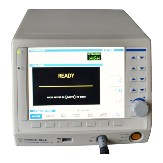
5 User Interface Overview Figure 5-1 Generator front panel Front Panel Displays, Controls, and Connections • Descriptions of front panel features and their functions are given below. Please refer to Figure 5-1 for location of each item on the front panel. (1) Status Window: This window is used to display messages (e.g., Error, Fault, Save Settings). - Page 12 (4) SETTINGS Window: For each state (e.g. VOLTAGE STIMULATION, AUTO TEMP LESION, TRANSDISCAL TREATMENT, etc.), the adjustable settings are shown in the SETTINGS Window. Up to 5 SETTINGS are adjustable in each state, by using the Setting Adjustment Keys (5) and Rotary Encoder (6), to the right of the window.
-
Page 13: Rear Panel Displays, Controls, And Connections
Figure 5-2 Generator rear panel Rear Panel Displays, Controls, and Connections • Descriptions of rear panel features and their functions are given below. Please refer to Figure 5-2 for corresponding locations on the rear panel. (1) Volume Adjustment: This knob adjusts the volume of the system’s audio output. (2) RS232 connection: This is an isolated connection to a standard 9-pin COM port. -
Page 14: Factory Set Defaults
6 Factory Set Defaults FACTORY SET DEFAULTS Mode Settings Adjustment Range “Factory Set” Value 2 Hz STIM RATE 1-Shot, 2, 5, 10, 20, 50, 75, 100, 150, 180, 200 Hz VOLTAGE 1.0 ms STIMULATION PULSE DUR 0.1, 0.2, 0.5, 1.0 ms VOLTAGE 0.0–10.0 V 0.0 V... -
Page 15: Displays
7 Displays System Initialization, Power-On-Self-Test (POST), and STANDBY States • The System Initialization state is initiated when the system is turned on and it lasts about 40 seconds. Figure 7-1 System Initialization State Display • The POST state is initiated after System Initialization is completed. It lasts about 30 seconds. Figure 7-2 POST State Display •... - Page 16 Displays and Indicators: PARAMETER RF/Stimulus Output ON/OFF STATE RF/Stimulus Output FAULT indicator indicator Status Description Status Description Status Description No RF or stimulus Only Power On is Only Power On is System waveforms are illuminated during illuminated during Initialization generated. Initialization.
-
Page 17: Placement State
PLACEMENT State • In the TRANSDISCAL mode, TREATMENT state is the default screen upon connection of a valid TransDiscal cable and probe, or when a TransDiscal Y-Connecting Cable is used. The PLACEMENT state can be accessed from the STIMULATION or TREATMENT READY states. The PLACEMENT state cannot be accessed during the STIMULATION ON or TREATMENT ON states. - Page 18 Displays and Indicators: PARAMETER STATUS DESCRIPTION RF/Stimulus Output RF power is not delivered during this state. (The FAULT indicator is used only in the POST and SYSTEM FAULT Indicator FAULT states.) The indicator is not illuminated during this state, as there is no RF RF/Stimulus Output power delivery.
- Page 19 PARAMETER STATE RF Audio Output Impedance Related Audio Output Graph Window Status Description Status Description Status Description TDP A PLACEMENT Continuous audio output is generated for placement. TDP B Frequency of output is related to active impedance Indicates the system PLACEMENT measurement.
-
Page 20: Ready States
READY States • VOLTAGE STIMULATION Mode – READY state is the default upon connection of a Baylis Pain Management Thermocouple probe and cable. Figure 7-5 VOLTAGE STIMULATION – READY Display Figure 7-6 MULTI-RF VOLTAGE STIMULATION – READY Display Displays and Indicators: PARAMETER STATUS DESCRIPTION... - Page 21 PARAMETER STATUS DESCRIPTION OFF (Default*) If enabled in ADVANCED AUDIO SETTINGS, impedance related audio Impedance Related Audio Output ON (if enabled) output is generated. The time axis ( ) is indefinitely scalable during the READY state, accommodating changes to treatment TIME. The dashed line denoting SET TEMP/TEMP LIMIT/WARNING TEMP will move according to changes made Minimal to the SET TEMP/TEMP LIMIT/WARNING TEMP value.
- Page 22 PARAMETER STATE Measurement Window Available States Available Settings Status Description Status Description Status Description SELECT Available PROBE A, B, C, or D While in the READY Values VOLTAGE (Multi-RF) state, other operating STIMULATION Range 1-Shot –200 Hz modes for Baylis Pain Available 1- Shot, 2, 5, 10, 20, 50, 75, 100, 150, Management...
- Page 23 PARAMETER STATE Measurement Window Available States Available Settings Status Description Status Description Status Description Range 38–95 ºC SET TEMP Increment 1 ºC VOLTAGE Default* 80 ºC AUTO TEMP STIMULATION LESION Range 15–600 s Temperature and TIME Increment CURRENT Impedance measurements Default* 75 s STIMULATION...
- Page 24 VOLTAGE Range 38–95 ºC WARNING STIMULATION Increment 1 ºC TEMP Default* 42 ºC Temperature and CURRENT While in the READY Impedance measurements Range 10–900 s STIMULATION state, other operating are displayed while Time TIME Increment modes for Baylis Pain and Power are not displayed Default* 120 s Management...
- Page 25 PARAMETER STATE Measurement Window Available Modes Available Settings Status Description Status Description Status Description Range 30–90 ºC If only one C ooled RF probe is used, the temperature of the Co oled RF probe is displayed in the COOLED VOLTAGE Increment 1 ºC TEMP...
- Page 26 PARAMETER STATE Measurement Window Available Modes Available Settings Status Description Status Description Status Description While in the READY Range 40–95ºC state, other operating Temperature of IDL and Thermocouple Probe are Increment 1 ºC modes are not TEMP displayed. Impedance measurement for IDL is available.
-
Page 27: On States
ON States Figure 7-7 VOLTAGE STIMULATION – ON Display Figure 7-10 MANUAL POWER LESION - ON Display Figure 7-8 CURRENT STIMULATION – ON Display Figure 7-11 AUTO PULSED LESION – ON Display Figure 7-9 AUTO TEMP LESION – ON Display Figure 7-12 MANUAL PULSED LESION –... -
Page 28: Figure 7-13 Multi-Rf Auto Temp Lesion - On Display
Figure 7-13 Multi-RF AUTO TEMP LESION – ON Display Figure 7-14 Multi-RF AUTO PULSED – ON Display • COOLED RF AUTO TEMP AND TRANSDISCAL TREATMENT states consist of: PRE-TREATMENT COOLING, TREATMENT ON, and POST-TREATMENT COOLING, if enabled from ADVANCED SETTINGS. Figure 7-15 COOLED RF AUTO TEMP ON Display Figure 7-16 TRANSDISCAL TREATMENT ON Display 025-0169-311 Revision: B... -
Page 29: Figure 7-17 Rfa Mode - Treatment On Display
Figure 7-17 RFA Mode – TREATMENT ON Display Figure 7-18 IDL Mode – ON Display (Secondary Thermocouple Enabled) Displays and Indicators: PARAMETER STATUS DESCRIPTION Stimulus Output ON Stimulus pulses are delivered during the ON state. RF power is delivered during the ON state. SET TEMP/TEMP LIMIT/WARNING LIMIT and treatment TIME remain modifiable during RF power delivery. - Page 30 PARAMETER STATUS DESCRIPTION Data is displayed. The time axis ( ) is indefinitely scalable during the ON state, accommodating changes to treatment TIME. The dashed line denoting SET TEMP/TEMP LIMIT/WARNING TEMP will move according to changes made to the SET TEMP/TEMP LIMIT/WARNING TEMP value.
- Page 31 PARAMETER STATE Measurement Window Available Modes Available Settings Status Description Status Description Status Description SELECT Range A, B, C or D PROBE* Increment VOLTAGE Range 1-Shot–200 Hz STIM RATE* STIMULATION Impedance † Available Values 1-Shot, 2, 5, 10, 20, 50, 75, 100, 150, 180, and 200 Hz measurements Range 0.1–1.0 ms...
- Page 32 PARAMETER STATE Measurement Window Available Modes Available Settings Status Description Status Description Status Description Range 30–90 ºC SET TEMP Increment 1 ºC COOLED RF Range 15s–30 min TREATMENT TIME 15 s (between 15 s and 5 min) Increment All measurements are displayed. 30 s (between 5 min and 30 min) Range 30–90 ºC...
-
Page 33: Done States
DONE States Displays and Indicators: PARAMETER STATUS DESCRIPTION Other modes are not selectable while in the DONE or ON state, as indicated by the greyed-out mode key labels. In the DONE state, SAVE SETTINGS is replaced with HOLD DISPLAY, which has the Available Modes HOLD DISPLAY function of holding the display. -
Page 34: Save Settings State
SAVE SETTINGS State Figure 7-19 Save Settings Display 7.6.1 Example Display • When the Save Settings button is pressed and held for 5 seconds the setting values in the current mode will become the new default values for those settings. ADVANCED SETTINGS Mode •... -
Page 35: Advanced Settings Mode- Lesion Settings State
• If LOCK AVAILABLE VALUES is set to NO, and the user selects SAVE SETTINGS from either the Voltage or Current Stimulation Mode, STIM RATE 1 and PULSE DUR 1 will be overwritten with the saved values. • Since the VOLTAGE STIMULATION and CURRENT STIMULATION modes are available from the COOLED RF AUTO TEMP READY and TRANSDISCAL TREATMENT READY modes, any changes made to the VOLTAGE STIMULATION and CURRENT STIMULATION modes through ADVANCED SETTINGS also affects the VOLTAGE STIMULATION and CURRENT STIMULATION modes when accessed through COOLED RF and... -
Page 36: Advanced Settings Mode - Cooled Rf Settings State
Figure 7-21 ADVANCED SETTINGS Mode- LESION SETTINGS Display Settings: Range/ Default Affected Mode Parameter DESCRIPTION Increment Units Value Ramp-up interval to temperature Auto Temp LESION RAMP TIME 10–60 s 15 s set point AUTO TEMP LESION, Maximum allowable power for POWER LIMIT 1–50 W 50 W... -
Page 37: Advanced Settings Mode - Transdiscal Settings State
Settings: Default Affected Mode Parameter DESCRIPTION Range/Units Increment Value Rate at which 0.5 ºC/min – 5 ºC/min 0.1 ºC/Min temperature increases After 5 ºC/min, next RAMP RATE from the INITIAL 80 ºC/Min value is 10 ºC/min TEMP to the SET 10–200 ºC/Min 10 ºC/Min TEMP... -
Page 38: Advanced Settings Mode - Rfa Settings State
Settings: Default Affected Mode Parameter DESCRIPTION Range/Units Increment Value PERIPHERAL Setpoint for the DISC WARNING Peripheral Disc 30–60 ºC 35 ºC 0.5 ºC TEMP Temperature Warning Rate at which 0.5 ºC/Min – 5 ºC/Min 0.1 ºC/Min temperature increases After 5 ºC/Min next RAMP RATE from the INITIAL 2 ºC/Min... -
Page 39: Advanced Settings Mode - Idl Settings State
Settings: Range/ Default Affected Mode Parameter DESCRIPTION Increment Units Value Treatment Mode SECONDARY Enable/disable optional ENABLE/ ENABLE THERMOCOUPLE thermocouple DISABLE Placement Mode Time in which temperature increases 15 – 60 s; 1 s (for 15-60 s); Treatment Mode RAMP TIME 15 s 1 –... -
Page 40: Advanced Settings Mode - Language Settings State
• Enabling Impedance Audio in All Stimulation Modes enables the tone in the Voltage and Current Stimulation – READY state • Enabling Impedance Audio in All Placement Modes enables the tone in the RFA and TransDiscal Placement Modes • Enabling Impedance Audio in All Ready States enables the tone in the Auto Temp, Manual Power, Auto Pulsed, Manual Pulsed, Cooled RF Auto Temp, TransDiscal Treatment Mode, and RFA Treatment Mode Ready States Figure 7-26 ADVANCED SETTINGS Mode –... -
Page 41: Special Event States
Special Event States 7.8.1 Recoverable Errors Figure 7-28 AUTO TEMP Recoverable Error Pop-Up Display 7.8.1.1 Display • Yellow “error” indicator will display on screen. • Error text will display in the center of the screen within the Status window. 7.8.1.2 Settings •... -
Page 42: Technical Specifications
8 Technical specifications Impedance Measurement • Range 1 to 3000 Ohms (Ω), 1 Ω resolution • Before and during lesion in LESION mode • Before STIMULATION mode • During TRANSDISCAL Placement mode • During Cooled RF Auto Temp mode • During TRANSDISCAL Treatment mode •... -
Page 43: Software Shutdown Limits During Rf Delivery Or Stimulation
Software Shutdown Limits During RF Delivery or Stimulation • < 25 Ω or > 3,000 Ω Measured Impedance: • < 15 °C, > 100 °C, or Measured Temperature: > SET TEMPERATURE +5 °C for 5 s, or > SET TEMPERATURE +10 °C for 1 s •... -
Page 44: Rated Accessory Voltage (For Associated Equipment And Active Accessories)
8.12 Rated Accessory Voltage (for Associated Equipment and Active Accessories) • 160 V 8.13 Output Power Graphs Power vs. Load At 50 Watt Setting 1000 1500 2000 2500 3000 Load Impedance (Ω Ω Ω Ω ) Power vs. Load At 25 Watt Setting 1000 1500 2000... -
Page 45: Figure 8-2 Set Power Vs. Output Power
+ 0.25 Watts + 5% Output Minimum Output Maximum Set Power (Watts) Figure 8-2 Set Power vs. Output Power 025-0169-311 Revision: B Page 43 of 52... -
Page 46: Iec Electrical Safety And Emc Specifications
8.14 IEC Electrical Safety and EMC Specifications Table 8-1 IEC Electrical Safety Specifications Device Description Class I, Defibrillation proof Type CF Equipment, IPX0, not AP/APG Mode of Operation: Continuous • Leakage current conforms to IEC 60601-1 • Dielectric withstanding Electrical Isolation voltage conforms to IEC 60601-1 EMC Emissions and Susceptibility: The Baylis Pain Management System has been tested and found to... - Page 47 Table 8-3 IEC EMC Specifications (Immunity) Guidance and Manufacturer’s Declaration – Electromagnetic Immunity The Baylis Pain Management System is intended for use in the electromagnetic environment specified below. The customer or the user of the Baylis Pain Management System should assure that it is used in such an environment. Electromagnetic environment - Immunity test IEC 60601 test level...
- Page 48 Guidance and Manufacturer’s Declaration – Electromagnetic Immunity (continued) The Baylis Pain Management System is intended for use in the electromagnetic environment specified below. The customer or the user of the Baylis Pain Management System should assure that it is used in such an environment. Electromagnetic environment - Immunity test IEC 60601 test level...
- Page 49 Field strengths from fixed transmitters, such as base stations for radio (cellular/cordless) telephones and land mobile radios, amateur radio, AM and FM radio broadcast and TV broadcast cannot be predicted theoretically with accuracy. To assess the electromagnetic environment due to fixed RF transmitters, an electromagnetic site survey should be considered.
- Page 50 Table 8-4 IEC Recommended Separation of RF Communication Equipment Recommended separation distances between portable and mobile RF communications equipment and the PMG system The Baylis Pain Management System is intended for use in an electromagnetic environment in which radiated RF disturbances are controlled.
-
Page 51: Standard Rf Lesion Size
9 Standard RF Lesion Size Lesion size and shape is determined by numerous factors including: • cannula active tip length • cannula active tip diameter • impedance of tissue • current intensity • length of time that energy is applied One published approximation method for lesion size and shape describes a lesion as a prolate spheroid in shape with the major axis = 2 x length of the active tip and the minor axis = 2/3 the major axis. -
Page 52: Labeling Symbols
10 Labeling Symbols Alternating Current Attention: Consult accompanying documents Authorized Representative in the European Community Catalogue Number Connector Cable connection Consult Instructions for Use Dangerous Voltage Defibrillator-proof, Patient Isolated connections Isolated Patient Circuit Dispersive Return Electrode connection Down Earth Ground Federal law (U.S.A) restricts this device to sale by or on the order of a physician Footswitch... - Page 53 Output ON Power OFF Power ON Pump Module Interface Connector Serial Number Time Please contact your distributor or the device manufacturer for recycling of this device 025-0169-311 Revision: B Page 51 of 52...
-
Page 54: Warranty
11 Warranty This warranty applies to customers in the United States only. Outside of the USA, contact your Baylis sales representative. Baylis warrants the products listed below against defects in both materials and workmanship to the registered owner at the time of purchase.
Need help?
Do you have a question about the Baylis PMG-115 and is the answer not in the manual?
Questions and answers