Table of Contents
Advertisement
Advertisement
Table of Contents
Troubleshooting

Related Manuals for Yamaha T135 SE 2016


Summary of Contents for Yamaha T135 SE 2016
- Page 1 55D-F8199-32...
- Page 2 Baca buku panduan dengan teliti sebelum mengendalikan motosikal ini. Buku panduan ini diberi percuma dengan pembelian motosikal Read this manual carefully before operating this vehicle. This manual should stay with this vehicle if it sold.
- Page 3 Yamaha a reputation for dependability. Please take the time to read this manual thoroughly, so as to enjoy all advantages of your Yamaha T135 SE. The Owner’s Manual does not only instruct you in how to operate, inspect and maintain your motorcycle, but also in how to safeguard yourself and others from trouble and injury.
- Page 4 IMPORTANT MANUAL INFORMATION Particularly important information is distinguished in this manual by the following notations: This is the safety alert simbol. It is used to alert you to potential personal injury hazards. Obey all safety messages that follow this simbol to avoid possible injury or death.
- Page 5 IMPORTANT MANUAL INFORMATION T135SE OWNER”S MANUAL ©2016 by Yamaha Motor CO., Ltd 1st edition, January 2016 All rights reserved. Any reprinting or unauthorized use without the written permission of Yamaha Motor Co., Ltd is expressly prohibited. Printed in Malaysia...
-
Page 6: Table Of Contents
TABLE OF CONTENTS LOCATION OF IMPORTANT LABELS..1-1 OPERATION AND IMPORTANT Checking the brake lever RIDING POINTS......... 5-1 free play ........6-22 SAFETY INFORMATION ....1-2 Starting and warming up a Adjusting the brake pedal DESCRIPTION ........2-1 cold engine ......... 5-1 free play ........6-22 Left view ..........2-1 Starting a warm engine .... - Page 7 TABLE OF CONTENTS Replacing a front turn signal light bulb or an auxiliary light bulb ..6-35 Rear turn signal light and tail/brake light ......6-35 Front wheel ........6-36 Rear wheel ........6-37 Troubleshooting ......6-39 Troubleshooting charts ....6-40 MOTORCYCLE CARE AND STORAGE ..........7-1 Care ..........7-1 Storage ...........7-3 SPECIFICATIONS ......8-1...
-
Page 8: Location Of Important Labels
Read and understand all of the labels on your vehicle. They contain important information for safe and proper operation of your vehicle. Never remove any labels from your vehicle. If a label becomes difficult to read or comes off, a replacement label is available from your Yamaha dealer. -
Page 9: Safety Information
SAFETY INFORMATION Safe Riding tersections are the most likely Be a Responsible Owner Perform the pre-operation checks each places for motorcycle accidents As the vehicle’s owner, you are respon- time you use the vehicle to make sure it to occur. sible for the safe and proper operation is in safe operating condition. - Page 10 SAFETY INFORMATION the operator is veering wide on a Never ride under the influence of tem become very hot during or af- turn due to excessive speed or un- alcohol or other drugs. ter operation and can cause dercornering (insufficient lean an- burns.
- Page 11 Yamaha accessories, which are avail- extra care when riding a motorcycle instability. able only from a Yamaha dealer, have that has added cargo or accessories. Shifting weights can create a sud- been designed, tested, and approved Here, along with the information about den imbalance.
- Page 12 Wind may at- Yamaha vehicles. Yamaha is not in a Keep the following guidelines in mind, tempt to lift the motorcycle, or position to test the products that these as well as those provided under “Load-...
-
Page 13: Description
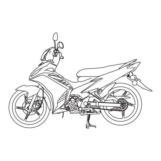
DESCRIPTION Left view 1. Front turn signal/auxiliary lights (page 6-35) 6. Seat lock (page 3-9) 2. Headlight (page 6-34) 7. Tail/brake light (page 6-35) 3. Battery (page 6-32) 8. Rear turn signal lights (page 6-35) 4. Storage compartment (page 3-10) 9. -
Page 14: Right View
DESCRIPTION Right view 9 8 7 6. Front brake fluid reservoir (page 6-24) 1. Kickstarter (page 3-9) 7. Engine oil filter element (page 6-11) 2. Fuel tank cap (page 3-6) 8. Brake pedal (page 3-6) 3. Fuse (page 6-33) 9. Engine oil drain bolt (page 6-11) 4. -
Page 15: Controls And Instruments
DESCRIPTION Controls and instruments 2 3 4 1. Left handlebar switches (page 3-4) 5. Right handlebar switch (page 3-5) 2. Speedometer unit (page 3-4) 6. Brake lever (page 3-6) 3. Fuel gauge (page 3-4) 7. Throttle grip (page 6-18) 4. Main switch/steering lock (page 3-1) -
Page 16: Instrument And Control Functions
INSTRUMENT AND CONTROL FUNCTIONS To unlock the steering LOCK Main switch/steering lock The steering is locked, and all electrical systems are off. The key can be re- moved. To lock the steering LOCK Insert the key and turn it to “OFF”. WARNING WARNING The main switch/steering lock controls... -
Page 17: Keyhole Cover
INSTRUMENT AND CONTROL FUNCTIONS Keyhole cover 1. push shut bottom To close the keyhole cover To open the keyhole cover 1. Shutter key Insert the key head into the key hole Push the push shut bottom after For open and close keyhole cover cover receptacle as shown, and remove the key. -
Page 18: Indicator And Warning Lights
This warning light also has a self-diag- This indicator light flashes when the nosis device function for various electri- cal circuit. Have a Yamaha dealer turn signal switch is pushed to the left or cal circuits. check the vehicle. -
Page 19: Speedometer Unit
INSTRUMENT AND CONTROL FUNCTIONS Speedometer unit Fuel gauge Handlebar switches Left 1. Speedometer 1. Fuel gauge 1. Dimmer switch “ ” 2. Odometer 2. Red zone 2. Turn signal switch “ ” The speedometer unit is equipped with The fuel gauge indicates the amount of 3. -
Page 20: Shift Pedal
INSTRUMENT AND CONTROL FUNCTIONS Right Shift pedal Turn signal switch “ ” To signal a right-hand turn, push this switch to “ ” To signal a left-hand turn, push this switch to “ ”. When re- leased, the switch returns to the center position. -
Page 21: Brake Lever
INSTRUMENT AND CONTROL FUNCTIONS Fuel tank cap Brake lever Brake pedal 1. Fuel tank cap 1. Brake pedal 1. Brake lever 2. “ ” mark The brake lever is located at the right The brake pedal is on the right side of To remove the fuel tank cap handlebar grip. -
Page 22: Fuel
INSTRUMENT AND CONTROL FUNCTIONS 3. Wipe up any spilled fuel imme- 1. Before refueling, turn off the engi- Fuel diately. NOTICE: Immediately ne and be sure that no one is sitt- wipe off spilled fuel with a cle- ing on the vehicle. Never refuel an, dry, soft cloth, since fuel while smoking, or while in the may deteriorate painted surfa-... -
Page 23: Catalytic Converter
INSTRUMENT AND CONTROL FUNCTIONS Catalytic converter Starter (choke) lever “ ” Recommended fuel: This model is equipped with a catalytic Regular unleaded gasoline only converter in the exhaust system. Fuel tank capacity: 4.0 L (1.06 US gal) (0.88 Imp.gal) WARNING WARNING The exhaust system is hot after op- NOTICE... -
Page 24: Kickstarter
INSTRUMENT AND CONTROL FUNCTIONS Seat Kickstarter Helmet holders 1. Kickstarter 1. Seat lock If the engine fails to start by pushing the 1. Helmet holder 2. Seat start switch, try to start it by using the The helmet holders are located under kickstarter. -
Page 25: Storage Compartment
INSTRUMENT AND CONTROL FUNCTIONS To release a helmet from a helmet Sidestand Storage compartment holder The sidestand is located on the left side Open the seat, remove the helmet from of the frame. Raise the sidestand or the helmet holder, and then close the lower it with your foot while holding the seat. -
Page 26: Pre-Operation Checks
Failure to inspect or maintain the vehicle properly increases the possibility of an accident or equipment damage. Do not operate the vehicle if you find any problem. If a problem cannot be corrected by the procedures provided in this manual, have the vehicle inspected by a Yamaha dealer. Before using this vehicles, check the following points:... -
Page 27: Pre-Operation Check List
• If necessary, add recommended coolant to specified level. 6-13 • Check cooling system for leakage. • Check operation. • If soft or spongy, have Yamaha dealer bleed hydraulic system. • Check brake pads for wear. Front brake • Replace if necessary. - Page 28 PRE-OPERATION CHECKS ITEM CHECKS PAGE • Check for damage. • Check tire condition and tread depth. Wheels and tires 6-19, 6-21 • Check air pressure. • Correct if necessary. • Make sure that operation is smooth. Brake pedal 6-29 • Lubricate pedal pivoting point if necessary. •...
-
Page 29: Operation And Important Riding Points
NOTICE should be on, otherwise have a Consult a Yamaha dealer re- Yamaha dealer check the electrical cir- Do not ride through deep water garding any control or function cuit. (including puddles), otherwise the that you do not thoroughly un- engine may be damaged. -
Page 30: Starting A Warm Engine
“ON”, and then go off af- ter a few seconds. If the coolant tem- perature warning light comes on after starting, immediately stop the engine, and have a Yamaha dealer check the electrical circuit. 6. After starting the engine, move the starter (choke) back halfway. -
Page 31: Shifting
OPERATION AND IMPORTANT RIDING POINTS Shifting Tips for reducing fuel consumption To shift the transmission into the neu- Fuel consumption depends largely on tral position, press the shift pedal your riding style. Consider the following down repeatedly until it reaches the tips to reduce fuel consumption: end of its travel, and then slightly Turn the starter (choke) off as... -
Page 32: Engine Break-In
OPERATION AND IMPORTANT RIDING POINTS 150–500 km (90–300 mi) 0–150 km (0–90 mi) Engine break-in There is never a more important period in the life of your engine than the period between 0 and 1000 km (600 mi). For this reason, you should read the follow- ing material carefully. -
Page 33: Parking
Never park in an area where there element replaced, and the oil strain- are fire hazards such as grass or er cleaned. If any engine trouble other flammable materials. should occur during the engine break-in period, immediately have a Yamaha dealer check the vehicle. -
Page 34: General Note
Much can be gained from the correct use and maintenance of a motorcycle. 1. THE CUSTOMERS CAN USE THE FULLEST 2. A MOTORCYCLE CAN KEEP ITS PERFORMANCE POTENTIAL OF YAMAHA MOTORCYCLES CAPABILITY FOR A LONGER TIME Comparison of wear on engine parts (piston, piston ring, cylinder, etc.) - Page 35 OPERATION AND IMPORTANT RIDING POINTS 3. FUEL COST AND REPAIR EXPENSES CAN BE 4. A MOTORCYCLE CAN DEMAND A HIGH PRICE KEPT TO A MINIMUM WHEN IT IS TRADED IN AS A USED PRODUCT Fuel consumption With maintenance 100% Without maintenance Distance covered (km) Customer’s running cost...
-
Page 36: Periodic Maintenance And Minor Repair
Yamaha dealer perform it for you. safest and most efficient condition pos- sible. The most important points of in- WARNING spection, adjustment, and lubrication are explained on the following pages. -
Page 37: Periodic Maintenance And Lubrication Chart
The annual checks must be performed every year, except if a kilometer-based maintenance is performed in- stead. From 12000 km, repeat the maintenance intervals starting from 3000 km. Items marked with an asterisk should be performed by a Yamaha dealer as they require special tools, data and technical skills ODOMETER READING (x 1000 km) ANNUAL... - Page 38 PERIODIC MAINTENANCE AND MINOR REPAIR ODOMETER READING (x 1000 km) ANNUAL ITEM CHECK OR MAINTENANCE JOB CHECK √ √ √ √ • Check runout and for damage. 9 * Wheels • Check tread depth and for damage. • Replace if necessary. √...
- Page 39 PERIODIC MAINTENANCE AND MINOR REPAIR ODOMETER READING (x 1000 km) ANNUAL ITEM CHECK OR MAINTENANCE JOB CHECK √ √ √ √ √ • Check coolant level and vehicle for coolant leakage. 22 * Cooling system • Change. Every 3 years Front and rear brake √...
-
Page 40: Removing And Installing The Cowlings And Panel
PERIODIC MAINTENANCE AND MINOR REPAIR The cowlings and panel shown above Removing and installing the Cowling C need to be removed to perform some of cowlings and panel To remove the cowling the maintenance jobs described in this Remove the bolts and screw shown, chapter. - Page 41 PERIODIC MAINTENANCE AND MINOR REPAIR 1. Bolt 1. Screw 1. Screw To install the cowling To install the cowling 1. Place the cowling in the original Place the cowling in the original posi- position, and then install the bolts tion, and then install the bolts and and screws.
-
Page 42: Checking The Spark Plug
PERIODIC MAINTENANCE AND MINOR REPAIR Panel A Checking the spark plug The spark plug is an important engine component, which is easy to check. Since heat and deposits will cause any spark plug to slowly erode, the spark plug should be removed and checked in accordance with the periodic mainte- nance and lubrication chart. - Page 43 PERIODIC MAINTENANCE AND MINOR REPAIR 1. Resonator bolt 1. Resonator 1. Spark plug wrench 2. Spark plug cap To remove the spark plug 5. Remove the spark plug as shown, 3. Move the resonator away as 1. Remove cowling B. (See page with the spark plug wrench includ- shown.
- Page 44 Do not attempt to diagnose such position, and then tighten the bolt problems yourself. Instead, have a to the specified torque. Spark plug gap: Yamaha dealer check the vehicle. 0.8–0.9 mm (0.031–0.035 in) Tightening torque: 2. Check the spark plug for electrode Resonator bolt: 2.
-
Page 45: Engine Oil And Oil Filter Element
PERIODIC MAINTENANCE AND MINOR REPAIR Engine oil and oil filter element The engine oil level should be checked before each ride. In addition, the oil must be changed and the oil filter ele- ment replaced at the intervals specified in the periodic maintenance and lubri- cation chart. - Page 46 PERIODIC MAINTENANCE AND MINOR REPAIR To change the engine oil (with or without oil filter element replace- ment) 1. Start the engine, warm it up for several minutes, and then turn it off. 2. Place an oil pan under the engine to collect the used oil.
- Page 47 PERIODIC MAINTENANCE AND MINOR REPAIR 8. Install the engine oil strainer, com- Recommended engine oil: pression spring, O-ring and engine See page 8-1. oil drain bolt, and then tighten the Oil quantity: drain bolt to the specified torque. With oil filter element replacement: 0.90 L (0.95 US qt, 0.79 Imp.qt) NOTICE: Before installing the Without oil filter element replace-...
-
Page 48: Coolant
PERIODIC MAINTENANCE AND MINOR REPAIR Coolant Be sure to wipe off spilled oil on any The coolant level must be checked The coolant level should be checked parts after the engine and exhaust sys- on a cold engine since the level before each ride. - Page 49 PERIODIC MAINTENANCE AND MINOR REPAIR system will not be protected against frost and corrosion. If water has been added to the coolant, have a Yamaha dealer check the antifreeze content of the coolant as soon as possi- ble, otherwise the effective- ness of the coolant will be reduced.
-
Page 50: Cleaning The Air Filter Element
Have a maintenance and lubrication chart. Yamaha dealer change the coolant. Clean the air filter element more fre- quently if you are riding in unusually WARNING! Never attempt to re- wet or dusty areas. - Page 51 PERIODIC MAINTENANCE AND MINOR REPAIR 4. Insert the air filter element into the air filter case with the arrow mark pointing inward. NOTICE: Make sure that the air filter element is properly seat- ed in the air filter case. The en- gine should never be operated without the air filter element in- stalled, otherwise the piston(s)
-
Page 52: Adjusting The Carburetor
Therefore, most car- checked and, if necessary, adjusted as follows at the intervals specified in the buretor adjustments should be left to a Yamaha dealer, who has the neces- periodic maintenance and lubrication sary professional knowledge and expe- chart. -
Page 53: Adjusting The Throttle Cable Free Play
Adjusting the throttle cable If the specified idling speed cannot be free play obtained as described above, have a Yamaha dealer make the adjustment. 4. Install the cowling. 1. Throttle stop screw 3. Check the engine idling speed and, if necessary, adjust it to spec- 1. -
Page 54: Valve Clearance
(b). must be adjusted by a Yamaha dealer 3. Tighten the locknut. at the intervals specified in the periodic Tire air pressure maintenance and lubrication chart. - Page 55 (minimum tread depth), if the tire has a WARNING nail or glass fragments in it, or if the Proper loading of your motorcycle is sidewall is cracked, have a Yamaha important for several characteristics dealer replace the tire immediately. Minimum tire tread depth (front and...
-
Page 56: Wheel
If any dam- cannot be guaranteed. age is found, have a Yamaha After extensive tests, only the dealer replace the wheel. Do not tires listed below have been ap-... -
Page 57: Checking The Brake Lever Free Play
WARNING brake lever end. If there is free play, After adjusting the drive chain The brake pedal free play should mea- have a Yamaha dealer inspect the slack or removing and installing sure 25.0–35.0 mm (0.98–1.38 in) at brake system. -
Page 58: Adjusting The Rear Brake Light Switch
Turn the adjusting nut while holding the indicator grooves have almost disap- rear brake light switch in place. To peared, have a Yamaha dealer replace make the brake light come on earlier, the brake pads as a set. turn the adjusting nut in direction (a). To make the brake light come on later, turn the adjusting nut in direction (b). -
Page 59: Checking The Front Brake Fluid Level
Be careful that water does not en- the wear limit line, have a Yamaha ter the master cylinder when refill- dealer replace the brake shoes as a the brake pads for wear and the brake ing. -
Page 60: Changing The Brake Fluid
Brake fluid may deteriorate paint- Drive chain slack Changing the brake fluid ed surfaces or plastic parts. Al- The drive chain slack should be Have a Yamaha dealer change the ways clean spilled fluid checked before each ride and adjusted brake fluid at the intervals specified in immediately. - Page 61 PERIODIC MAINTENANCE AND MINOR REPAIR To adjust the drive chain slack Right side 1. Drive chain slack 1. Brake pedal free play adjusting nut 1. Axle nut Drive chain slack : 2. Axle nut 2. Adjusting plate 25.0–35.0 mm (0.98–1.38 in) 3.
-
Page 62: Cleaning And Lubricating The Drive Chain
Make sure that both adjusting plates brake light. drive chain with a brush or cloth. are in the same position for proper wheel alignment. TIP : For a thorough cleaning, have a Yamaha dealer remove the drive chain and soak it in solvent. 6-27... -
Page 63: Checking And Lubricating The Cables
PERIODIC MAINTENANCE AND MINOR REPAIR Checking and lubricating the Checking and lubricating the 2. Spray Yamaha Chain and Cable Lube or a high-quality spray-type cables throttle grip and cable drive chain lubricant on both sides The operation of all control cables and... -
Page 64: Lubricating The Brake Lever
Engine oil If the centerstand or sidestand does not move up and down smoothly, have a Yamaha dealer check or re- pair it. Recommended lubricant: Lithium-soap-based grease (all-pur- pose grease) -
Page 65: Lubricating The Swingarm Pivots
If any damage is found or the front tion.WARNING! To avoid injury fork does not operate smoothly, have a Yamaha dealer check or re- securely support the vehicle so pair it. that there is no danger of it fall ling over. -
Page 66: Checking The Steering
2. Hold the lower ends of the front fork legs and try to move them for- play can be felt, have a Yamaha dealer check or repair the steering. 6-31... -
Page 67: Battery
Avoid any contact with To charge the battery skin, eyes or clothing and al- Have a Yamaha dealer charge the bat- ways shield your eyes when tery as soon as possible if it seems to working near batteries. In case have discharged. -
Page 68: Replacing The Fuse
If the fuse is blown, replace it as fol- 4. If the fuse immediately blows 4. After installation, make sure that lows. again, have a Yamaha dealer the battery leads are properly con- 1. Turn the key to “OFF” and turn off check the electrical system. -
Page 69: Replacing A Headlight Bulb
1. Headlight bulb holder 4. Install the cowling. WARNING If a headlight bulb burns out, replace 5. Have a Yamaha dealer adjust the as follows. Headlight bulbs get very hot. There- headlight beam if necessary. 1. Remove cowling A. (See page fore, keep flammable products away 6-5.) -
Page 70: Replacing A Front Turn Signal Light Bulb Or An Auxiliary Light Bulb
If a rear turn signal light or the tail/brake light does not come on, have a Yamaha dealer check its electrical circuit or re- place the bulb. 1. Bulb 3. Remove the defective bulb by pull- 1. -
Page 71: Front Wheel
PERIODIC MAINTENANCE AND MINOR REPAIR Front wheel 1. Speedometer gear unit 1. Speedometer cable 1. Speedometer cable 2. Axle nut and washer To install the front wheel 2. Axle nut and washer 1. Install the speedometer gear unit 4. Pull the wheel axle out, and then into the wheel hub so that the pro- To remove the front wheel remove the wheel. -
Page 72: Rear Wheel
4. Take the motorcycle off the center- WARNING WARNING stand so that the front wheel is on the ground. It is advisable to have a Yamaha 5. Tighten the axle nut to the speci- dealer service the wheel. fied torque. Securely support the motor-... - Page 73 PERIODIC MAINTENANCE AND MINOR REPAIR TIP: The drive chain does not need to be disassembled in order to remove and install the wheel. 7. Remove the wheel. To install the rear wheel 1. Install the drive chain onto the rear sprocket.
-
Page 74: Troubleshooting
However, should your motorcycle Tightening torques: require any repair, take it to a Yamaha Brake torque rod nut: 19 Nm (1.9 m·kgf, 14 ft·lbf) dealer, whose skilled technicians have... -
Page 75: Troubleshooting Charts
Remove the spark plug and check the electrodes. The engine does not start. Have a Yamaha dealer check the vehicle. Check the battery. 4. Battery The engine turns over The battery is good. - Page 76 Start the engine. If the engine overheats again, have a The coolant level Yamaha dealer check and repair the cooling system. is OK. TIP: If coolant is not available, tap water can be temporarily used instead, provided that it is changed to the recommended coolant as soon as possible.
-
Page 77: Motorcycle Care And Storage
MOTORCYCLE CARE AND STORAGE Care ucts onto seals, gaskets, sprock- cleaning products, solvent or ets, the drive chain and wheel thinner, fuel (gasoline), rust re- While the open design of a motorcycle axles. Always rinse the dirt and de- movers or inhibitors, brake flu- reveals the attractiveness of the tech- greaser off with water. - Page 78 MOTORCYCLE CARE AND STORAGE After normal use 4. To prevent corrosion, it is recom- NOTICE Remove dirt with warm water, a mild mended to apply a corrosion pro- detergent, and a soft, clean sponge, Do not use warm water since it in- tection spray metal,...
-
Page 79: Storage
To prevent corrosion, avoid TIP: fuel tank. damp cellars, stables (because Consult a Yamaha dealer for advice on 4. Fill up the fuel tank and add fuel of the presence of ammonia) what products to use. stabilizer (if available) to prevent... - Page 80 MOTORCYCLE CARE AND STORAGE 5. Perform the following steps to pro- °C (90 °F)]. For more information WARNING tect the cylinder, piston rings, etc. on storing the battery, see page To prevent damage or injury from from corrosion. 6-28. sparking, make sure to ground the a.
-
Page 81: Specifications
Primary reduction ratio: Minimum turning radius: 69/24 (2.875) Coolant reservoir capacity (maximum 1930 mm (76.0 in) Secondary reduction system: level) YAMAHA GENUINE COOLANT: Weight: Chain drive 0.28 L (0.30 US qt) (0.25 Imp.qt) With oil and fuel: Secondary reduction ratio:... - Page 82 SPECIFICATIONS Tire air pressure (measured on cold Chassis: Rear brake: tires): Frame type: Type: Loading condition: Diamond Drum brake 0–90 kg (0–198 lb) Caster angle: Operation: Front: 25.60 ° Right foot operation 200 kPa (29 psi) (2.00 kgf/cm²) Trail: Front suspension: Rear: 80.0 mm (3.1 in) Type:...
- Page 83 SPECIFICATIONS Bulb voltage, wattage x quantity: Headlight: 12 V, 32 W/32.0 W x 1 Tail/brake light: 12 V, 3.0 W x 1 Front turn signal light: 12 V, 10.0 W x 2 Rear turn signal light: 12 V, 10.0 W x 2 Auxiliary light: 12 V, 0.8 W x 2 Meter lighting:...
-
Page 84: Consumer Information
Record the key identification number, vehicle identification number and en- gine serial number in the spaces pro- vided below for assistance when ordering spare parts from a Yamaha dealer or for reference in case the vehi- cle is stolen. KEY IDENTIFICATION NUMBER: 1. - Page 85 CONSUMER INFORMATION Engine serial number 1. Engine serial number The engine serial number is stamped into the crankcase.