Table of Contents
Advertisement
Quick Links
MANUFACTURED BY:
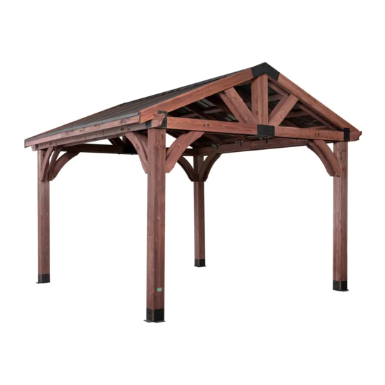
12x10 BROOKDALE GAZEBO
Backyard Discovery
3305 Airport Drive
WITH ELECTRIC
Pittsburg, KS 66762
Owner's Manual & Assembly Instructions
Model # 1806528
800-856-4445
Before you begin
average 2 person assembly time
FOR QUICK &
EASY ASSEMBLY
FIND 3D INSTRUCTIONS
9
FOR THIS PRODUCT IN
DOWNLOAD THE FREE APP
assembly time may vary based on skill level
For the most up to date assembly manual,
to register your set, or to order replacement parts please visit
www.backyarddisovery.com
SAVE THIS ASSEMBLY MANUAL FOR FUTURE REFERENCE IN THE
EVENT THAT YOU NEED TO ORDER REPLACEMENT PARTS.
Para obtener instrucciones en español, visite www.backyarddiscovery.com
Made in China | INS-1806528-A-BROOKDALE-ENG 10-9-18
Advertisement
Table of Contents

Subscribe to Our Youtube Channel
Related Manuals for Backyard Discovery 12x10 BROOKDALE GAZEBO


Summary of Contents for Backyard Discovery 12x10 BROOKDALE GAZEBO
- Page 1 MANUFACTURED BY: 12x10 BROOKDALE GAZEBO Backyard Discovery 3305 Airport Drive WITH ELECTRIC Pittsburg, KS 66762 Owner’s Manual & Assembly Instructions Model # 1806528 800-856-4445 Before you begin average 2 person assembly time FOR QUICK & EASY ASSEMBLY FIND 3D INSTRUCTIONS...
- Page 2 INSTALLATION SERVICES AVAILABLE! Need a helping hand? Let our team of professionals handle the installation for you! *Installation services are only available to U.S. customers. With Go Con! gure, we bring you 18 years of experience right to your doorstep. We service a wide array of indoor and outdoor recreation products that most consumers don’t have the time or ability to deliver &...
- Page 3 Owner’s Manual Please Read This Before Starting Assembly MISSING A PART? CALL US BEFORE GOING BACK TO THE STORE The store where you made your purchase does not stock parts for this item. If you have assembly questions or you are missing or have damaged parts, please call 1-800-856-4445 you can also visit www.backyarddiscovery.com...
- Page 4 Botanical, Adventure Playsets, and Leisure Time Products. Backyard Discovery warrants that this product is free from defect in materials and workmanship for a period of one (1) year from the original date of purchase. This one (1) year warranty covers all parts including wood, hardware, and accessories. All wood carries a ! ve (5) year pro-rated warranty against rot and decay. Refer to the schedule below for charges associated with replacement of parts under this Limited Warranty.
- Page 5 Owner’s Manual Safety Warnings and Maintenance Instructions WARNING IT IS IMPORTANT TO CHECK AND TIGHTEN ALL HARDWARE AT THE BEGINNING AND DURING THE SEASON AS THEY MAY LOOSEN DUE TO WOOD EXPANSION AND CONTRACTION. • Oil all metallic moving parts monthly during the usage •...
- Page 6 About Our Wood Backyard Discovery uses 100% Cedar (C. Lanceolata) wood. Although we take great care in selecting the best quality lumber available, wood is still a product of nature and susceptible to weathering which can change the appearance of your set.
- Page 7 Owner’s Manual Assembly Tips Protrusion Hazard Incorrect Correct If you see exposed threads and your bolt protrudes beyond the T-Nut you may have over tightened the bolt or used incorrect hardware. If you’ve overtightened, remove the bolt and add washers to eliminate the protrusion.
- Page 8 Owner’s Manual Assembly Tips ASSEMBLY TIP: Keep an eye out for these boxes which will contain helpful pictures and information making the assembly process as quick and painless as possible. Sorting Wood When removing the wood from the boxes we recommend arranging them by part number before you begin assembly.
- Page 9 Owner’s Manual Tools Required for Installation (These are the tools that are generally required for assembly of our outdoor products. These tools are not included with the outdoor product purchase.) (Square) (Level 24") (Phillips Screw Driver) (Rubber Mallet - Optional) (Tape Measure) (Drill Attachments: Phillips (3/16"...
- Page 10 Basic Setup Dimensions Install unit on level ground. Check carefully for overhead lines and ensure there is at least 6ft (2m) clearance from the roof to any overhead lines. 12'-1" [3683 mm] 11'-2 3/16" 10'-0" [3408 mm] [3048 mm] 12'-1" [3683 mm] 10'-2 7/8"...
- Page 11 Important Note: In the event the INK STAMP identifier is not easy to read or is missing from a wood component, match the unique geometric shape and dimensions of the wood component found in a specific assembly step to the PARTS IDENTIFICATION section when required.
- Page 12 Important Note: In the event the INK STAMP identifier is not easy to read or is missing from a wood component, match the unique geometric shape and dimensions of the wood component found in a specific assembly step to the PARTS IDENTIFICATION section when required.
- Page 13 Important Note: In the event the INK STAMP identifier is not easy to read or is missing from a wood component, match the unique geometric shape and dimensions of the wood component found in a specific assembly step to the PARTS IDENTIFICATION section when required.
- Page 14 Important Note: Backyard Discovery recommends taking all the hardware out of the box and arranging them by type before you begin assembly. This will allow for faster assembly and easy identification of any hardware that may be missing or damaged so they can be replaced before assembly.
- Page 15 Important Note: Backyard Discovery recommends taking all the hardware out of the box and arranging them by type before you begin assembly. This will allow for faster assembly and easy identification of any hardware that may be missing or damaged so they can be replaced before assembly.
- Page 16 Parts Identification Accessories (NOT TO SCALE) - "A" REVISION TAG - A100314 - BYD ID TAG (SMALL) WITHOUT AGES - A100241 - ROOF BRACKET - A4M00961 - L BRACKET 66x66x127 - BLK - A4M00619 - BRACKET - A4M00973 - BRACKET - A4M00972 - BRACKET - A4M00979 - BRACKET - A4M00974...
- Page 17 Parts Identification Accessories (NOT TO SCALE) - PLASTIC BOX - A6P00312 - 6x6 POST FOOT - A6P00308 - PLASTIC OUTLET - A6P00280 - POST ANCHORING PLATE WITH FLANGE - A4M00977 - DRIP EDGE 29 GA SPLICE - A4M00983 - POST PLATE - A4M00978 (1) 4' PAVILION ELECTRIC KIT - A6P00265...
- Page 18 Parts Identification Accessories (NOT TO SCALE) - 29 GA STEEL SHEETING - A4M00980 .014"x37.01"x77.75" (.34x940x1975) - 6 X 6 HIP/RIDGE CAP 29 GA - A4M00976 84" (2134) - 6 X 6 HIP/RIDGE CAP 29 GA - A4M00981 29" (737) - DRIP EDGE 29 GA - A4M00982 58 3/8"...
- Page 19 (2) P1 - POST - W2A02607 6"x6"x92" (152x152x2338) - 6x6 POST FOOT - A6P00308 (2) P2 - POST - W2A02610 6"x6"x92" (152x152x2338) STEP 1 COMPLETE THIS STEP TWICE SCREW PFH 8x1-1/2 (16) BLK H100200 TIP: FOR EASE OF ASSEMBLY WE RECOMMEND USING SAW HORSES FOR STEPS 1 THROUGH 3.
- Page 20 2'-1" [636 mm] (2) P3 - POST - W2A02611 6"x6"x33 1/4" (152x152x845) - BRACKET - A4M00972 D2 - BEAM - W4L11745 1 3/8"x5 1/4"x64 5/8" (36x134x1640) PILOT HOLE DOWN - L BRACKET 66x66x127 - BLK - A4M00619 - BRACKET - A4M00974 STEP 2 NUT BARREL WH (24)
- Page 21 (8) AB2 - ANGLE BRACE - W2A02609 1 5/16"x6 7/16"x35 3/4" (34x163x908) STEP 3 NUT BARREL WH LAG SCREW WH BOLT WH 5/16x2-1/4 (16) (16) 5/16x7/8 BLK 5/16x3 BLK H100206 BLK H100205 H100192 COMPLETE THIS STEP TWICE WASHER LOCK EXT WASHER LOCK EXT (24) (16)
- Page 22 D4 - BEAM - W4L11740 1 3/8"x5 1/4"x102 3/8" (36x134x2600) STEP 4 WASHER LOCK EXT 12x19 BLK BOLT WH 5/16x1 BLK (8 PLCS) H100468 NUT BARREL WH 5/16x7/8 (8 PLCS) NUT BARREL WH 5/16x7/8 BLK H100192 WASHER LOCK EXT 12x19 BLK H100199 BOLT WH 5/16x1 BLK (8 PLCS)
- Page 23 D1 - BEAM - W4L11744 1 3/8"x5 1/4"x111 1/8" (36x134x2824) - BRACKET - A4M00979 D3 - BEAM - W4L11737 1 3/8"x5 1/4"x11 1/2" (36x134x292) STEP 5 WASHER LOCK EXT 12x19 BLK BOLT WH 5/16x6 1/2 (16 PLCS) (16) BLK H100354 NUT BARREL WH 5/16x1-1/2 BLK (16 PLCS) NUT BARREL WH...
- Page 24 (8) AB1 - ANGLE BRACE - W2A02608 1 5/16"x6 7/16"x35 3/4" (34x163x908) STEP 6 NUT BARREL WH 5/16x7/8 (16 PLCS) NUT BARREL WH BOLT WH 5/16x2-1/4 (16) (16) 5/16x7/8 BLK BLK H100205 H100192 WASHER LOCK EXT 12x19 BLK (16 PLCS) WASHER LOCK EXT 8x19 BLK LAG SCREW WH 5/16x3 BLK H100206...
- Page 25 (2) RP1 - END RAFTER - W2A02606 D6 - ANGLE BRACE - W4L11736 2 7/8"x5 1/4"x80 5/8" (72x134x2048) 1 3/8"x5 1/4"x30 1/4" (36x134x769) - BRACKET - A4M00973 (2) RP2 - END RAFTER - W2A02612 2 7/8"x5 1/4"x80 5/8" (72x134x2048) STEP 7 ENSURE THAT HOLES ARE ALIGNED WITH POST HOLES, BY TEMPORARILY INSTALLING LONG 5/16"...
- Page 26 H1 - RAFTER - W4L11742 E1 - OUTSIDE RAFTER - W4L11741 1"x3 3/8"x105 1/8" (24x86x2670) 1 3/8"x3 3/8"x77 3/8" (36x86x1965) H2 - FASCIA - W4L11743 E2 - RAFTER - W4L11738 1 3/8"x3 3/8"x77 3/8" (36x86x1965) 1"x3 3/8"x59 3/8" (24x86x1507) STEP 8 COMPLETE THIS STEP TWICE SCREW PFH 8x2 BLK (30)
- Page 27 E3 - SHEATHING BOARD - W4L11739 E4 - SHEATHING BOARD - W4L11746 1 3/8"x3 3/8"x91 3/4" (36x86x2330) 1 3/8"x3 3/8"x27 1/4" (36x86x692) STEP 9 COMPLETE THIS STEP TWICE SCREW PFH 8x2 BLK (40) BOLT WH 5/16x1 1/4 H100391 (16) BLK H100459 T-NUT 5/16 BLK (16) H100379...
- Page 28 NOTE: USE THIS PAGE TO FAMILIARIZE YOURSELF WITH THE ROOF PANEL & ASSIST YOU IN THE COMING STEPS. WARNING: GLOVES SHOULD BE WORN WHEN HANDLING ROOF PANELS; EDGES ARE SHARP. STEP 10 • Due to the roof panels mirroring each other you will start the first roof panel working from PREPARATION left to right and the second roof panel working from right to left as shown.
- Page 29 - 29 GA STEEL SHEETING - A4M00980 .014"x37.01"x77.75" (.34x940x1975) STEP 11 SQUARE ROOF PANEL THEN INSTALL METAL SHEETING WITH SUPPLIED HARDWARE AS SHOWN. #10-16 X 1 1/4" TO ENSURE THAT SCREWS ARE CENTERD ON THE SHEATHING BOARDS (16) WOODGRIP SCREW USE THE DIMENSIONS BELOW TO MARK LOCATIONS.
- Page 30 STEP 12 SQUARE ROOF PANEL THEN INSTALL METAL SHEETING WITH SUPPLIED HARDWARE AS SHOWN. #10-16 X 1 1/4" TO ENSURE THAT SCREWS ARE CENTERD ON THE SHEATHING BOARDS (48) WOODGRIP SCREW USE THE DIMENSIONS BELOW TO MARK LOCATIONS. H100760 #10-16 X 1 1/4" WOODGRIP SCREW (24 PLCS) SHEATHING BOARD TIP:...
- Page 31 - 29 GA STEEL SHEETING - A4M00980 .014"x37.01"x77.75" (.34x940x1975) STEP 13 SQUARE ROOF PANEL THEN INSTALL METAL SHEETING #10-16 X 1 1/4" (72) WOODGRIP SCREW WITH SUPPLIED HARDWARE AS SHOWN. H100760 ENSURE THAT SCREWS ARE CENTERD ON THE SHEATHING BOARDS. #10-16 X 1 1/4"...
- Page 32 - 29 GA STEEL SHEETING - A4M00980 .014"x37.01"x77.75" (.34x940x1975) STEP 14 SQUARE ROOF PANEL THEN INSTALL METAL SHEETING WITH SUPPLIED HARDWARE AS SHOWN. #10-16 X 1 1/4" TO ENSURE THAT SCREWS ARE CENTERD ON THE SHEATHING BOARDS (16) WOODGRIP SCREW USE THE DIMENSIONS BELOW TO MARK LOCATIONS.
- Page 33 STEP 15 SQUARE ROOF PANEL THEN INSTALL METAL SHEETING WITH SUPPLIED HARDWARE AS SHOWN. #10-16 X 1 1/4" TO ENSURE THAT SCREWS ARE CENTERD ON THE SHEATHING BOARDS (48) WOODGRIP SCREW USE THE DIMENSIONS BELOW TO MARK LOCATIONS. H100760 #10-16 X 1 1/4" WOODGRIP SCREW (24 PLCS) SHEATHING BOARD TIP:...
- Page 34 - 29 GA STEEL SHEETING - A4M00980 .014"x37.01"x77.75" (.34x940x1975) STEP 16 SQUARE ROOF PANEL THEN INSTALL METAL SHEETING #10-16 X 1 1/4" (72) WOODGRIP SCREW WITH SUPPLIED HARDWARE AS SHOWN. H100760 ENSURE THAT SCREWS ARE CENTERD ON THE SHEATHING BOARDS. TIP: AFTER MARKING SCREW LOCATIONS, IT...
- Page 35 - DRIP EDGE 29 GA - A4M00982 - DRIP EDGE 29 GA SPLICE - A4M00983 58 3/8" (1483) STEP 17 COMPLETE THIS STEP TWICE (16) 1/4-14 x 3/4" SELF DRILLING SCREW H100759 NOTE: SCREWS GO THROUGH DRIP EDGE AND THEN THE TOP OF THE RIBS.
- Page 36 STEP 18 COMPLETE THIS STEP TWICE BOLT WH 5/16x8 BLK H100765 WITH AT LEAST TWO PEOPLE LIFT ASSEMBLED ROOF PANEL AND SLIDE IT INTO THE TRACKS ON THE RAFTERS. ONCE IN PLACE, INSTALL ATTACHMENT HARDWARE. NUT BARREL WH WASHER LOCK EXT 5/16x1-1/2 BLK 12x19 BLK H100199 H100193...
- Page 37 STEP 19 NUT BARREL WH BOLT WH 5/16x1 1/2 5/16x7/8 BLK BLK H100407 H100192 WASHER LOCK EXT WASHER LOCK EXT 8x19 BLK H100198 12x19 BLK H100199 BOLT WH 5/16x1-1/2 BLK (4 PLCS) WASHER LOCK EXT 8x19 BLK (4 PLCS) WASHER LOCK EXT 12x19 BLK (4 PLCS) NUT BARREL WH 5/16x7/8 (4 PLCS)
- Page 38 D7 - ANGLE BRACE - W4L11748 1 3/8"x5 1/4"x32 3/8" (36x134x823) STEP 20 COMPLETE BOTH ENDS BOLT WH 5/16x2-1/2 BLK H100194 BOLT WH 5/16x2-1/4 BLK H100205 NUT BARREL WH (16) 5/16x7/8 BLK H100192 WASHER LOCK EXT (16) 12x19 BLK H100199 WASHER LOCK EXT 8x19 BLK H100198 NUT BARREL WH 5/16x7/8...
- Page 39 - ROOF BRACKET - A4M00961 STEP 21 SCREW PWH 8x1-1/4 (30) BLK H100536 NOTE: CENTER ROOF BRACKETS ON EACH RAFTER AND ATTACH. SCREW PWH 8x1-1/4 BLK (30 PLCS) ROOF BRACKET (6 PLCS)
- Page 40 - 6 X 6 HIP/RIDGE CAP 29 GA - A4M00976 - 6 X 6 HIP/RIDGE CAP 29 GA - A4M00981 84" (2134) 29" (737) STEP 22 (12) 1/4-14 x 3/4" SELF DRILLING SCREW 1/4-14 x 3/4" SHEET METAL SCREW H100759 (12 PLCS) 6 X 6 HIP/RIDGE CAP 29 GA 6 X 6 HIP/RIDGE CAP 29 GA...
- Page 41 G5 - CORD COVER - W4L11749 (1) 4' PAVILION ELECTRIC KIT - A6P00265 1"x5 1/4"x43 5/8" (24x134x1109) J8 - CORD COVER - W4L11750 1"x2 3/8"x7 7/8" (24x60x201) STEP 23 SCREW PFH 8x2-1/2 PRESS THE ELECTRICAL CORD ASSEMBLY INTO THE BLK H100201 CUT OUTS ON THE G5 CORD COVER, AS SHOWN.
- Page 42 - POST PLATE - A4M00978 - POST ANCHORING PLATE WITH FLANGE - A4M00977 STEP 24 LAG SCREW WH (32) 5/16x1 1/2 BLK H100471 LAG SCREW WH 5/16x1 1/2 BLK (32 PLCS) POST PLATE (8 PLCS) INSIDE CORNERS POST ANCHORING PLATE WITH FLANGE (8 PLCS) OUTSIDE CORNERS...
- Page 43 - BYD ID TAG (SMALL) WITHOUT AGES - A100241 - "A" REVISION TAG - A100314 STEP 25 SCREW PFH 8x1-1/2 BLK H100200 SCREW PFH 8X1-1/2 BLK (2 PLCS) BYD ID TAG (SMALL) WITHOUT AGES (1 PLCS) FRONT SCREW PFH 8X1-1/2 BLK (2 PLCS) "A"...
- Page 44 NOTE: MANUFACTURER RECOMMENDS INSTALLATION ON CONCRETE SURFACE OR CONCRETE POST PADS. SEE BELOW. FOR INSTALLATION ON WOOD DECK, YOU MUST ENSURE THERE IS AMPLE STRUCTUAL SUPPORT UNDER DECK. STEP 26 CONCRETE ANCHOR (16) 1/4" x 2" H100120 WASHER FLAT 8x19 (16) BLK H100630 CONCRETE ANCHOR 1/4"...
Need help?
Do you have a question about the 12x10 BROOKDALE GAZEBO and is the answer not in the manual?
Questions and answers