
Related Manuals for SST Automation GT200-MT-EI


Summary of Contents for SST Automation GT200-MT-EI
- Page 1 Modbus TCP / EtherNet/IP Gateway GT200-MT-EI User Manual REV 1.4 SST Automation SUPPORT@SSTCOMM.COM E-mail: WWW.SSTCOMM.COM...
-
Page 2: Table Of Contents
GT200-MT-EI Modbus TCP/EtherNet IP Gateway User Manual Catalog 1 Product Overview..............................4 1.1 Product Overview............................4 1.2 Product Features............................. 4 1.3 Technical Specifications..........................4 2 Quick Start Guide..............................6 2.1 Connect to the power............................6 2.2 Ethernet Interface............................7 2.3 DIP Switch..............................7 2.4 Software Installation............................ - Page 3 GT200-MT-EI Modbus TCP/EtherNet IP Gateway User Manual 4.8 Excel File Output............................29 4.9 Monitor I/O Data............................30 5 Working Principle of Modbus TCP Master......................33 6 Working Principle of Modbus TCP Slave....................... 34 6.1 Working Principle............................34 6.2 Network Status Monitor..........................34 7 EtherNet/IP Connection Parameters Set........................
-
Page 4: Product Overview
1 Product Overview 1.1 Product Overview GT200-MT-EI is a gateway which can realize the interconnection of different industrial Ethernet devices. The gateway supports Modbus TCP master/slave and EtheNet/IP slave. It can finish the data exchange between Modbus TCP network and EtherNet/IP network. Also, it supports the interconnection between Schneider PLC and AB PLC and connecting the Modbus TCP slave devices to the EtherNet/IP network. - Page 5 GT200-MT-EI Modbus TCP/EtherNet IP Gateway User Manual [7] As Modbus TCP master, support visiting at most 36 different IP or Modbus TCP slave of different unit ID, support function code 01H, 02H,03H, 04H, 05H, 06H, 0FH, 10H; [8] Act as slave at the Modbus TCP side, support 36 TCP connections, support function code 03H, 04H, 06H, 10H;...
-
Page 6: Quick Start Guide
GT200-MT-EI Modbus TCP/EtherNet IP Gateway User Manual 2 Quick Start Guide 2.1 Connect to the power Use DC 24V power supply, dual power interface, redundant function. User can use one power route or two routes to provide supply. When using two powers to supply power, another power can keep supplying power to ensure the normal operation of equipment if one power fails. -
Page 7: Ethernet Interface
GT200-MT-EI Modbus TCP/EtherNet IP Gateway User Manual 2.2 Ethernet Interface Ethernet interface uses RJ-45 connector, 10/100M self-adaptive. Signal Description TXD+, Tranceive Data+, Output TXD-, Tranceive Data-, Output RXD+, Receive Data+, Input Bi-directional Data+ Bi-directional Data- RXD-, Receive Data-, Input Bi-directional Data+ Bi-directional Data- 2.3 DIP Switch... -
Page 8: Software Installation
Note: The network factory setting of GT200-MT-EI is DHCP. If no DHCP Server on the network, users can pull the bit 1 to ON and restart GT200-MT-EI to make the settings take effect. Now, the IP address of GT200-MT-EI is 192.168.0.10 (fixed), subnet mask is 255.255.255.0, gateway address is 192.168.0.1. -
Page 9: Hardware Description
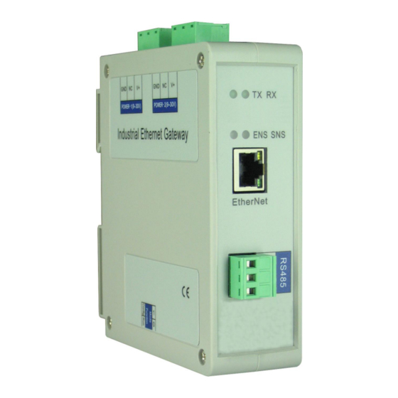
GT200-MT-EI Modbus TCP/EtherNet IP Gateway User Manual 3 Hardware Description 3.1 Appearance Dual power interface Indicators(reserved) Ethernet indicators Ethernet RJ45 interface Configuration switch WWW.SSTCOMM.COM... -
Page 10: Indicators
Configuration mode, IP address is 192.168.0.10 (fixed), this mode can read and write configuration data but cannot finish communication between EtherNet/IP and Modbus Reserved Notes: Restart GT200-MT-EI (power off and power on) after resetting the configuration to make the configuration take effect! WWW.SSTCOMM.COM... -
Page 11: Interface
GT200-MT-EI Modbus TCP/EtherNet IP Gateway User Manual 3.4 Interface 3.4.1 Power Interface GT200-MT-EI has two power interfaces and power redundant function. When one power fails, another power can keep supplying power. Function NC, not connected 24V+ , DC 24V 3.4.2 Ethernet Interface Ethernet interface uses RJ-45 connector;... -
Page 12: Instructions Of Configuration Software
Double click the software icon on the desktop after installation to enter the “Select device” interface: Select “GT200-MT-EI”, click OK to enter into the main interface of GT200-MT-EI (enter into the default parameters setting interface of EtherNet/IP. Click the Ethernet type of equipment view interface to switch the parameters setting interface. - Page 13 GT200-MT-EI Modbus TCP/EtherNet IP Gateway User Manual Title Bar Menu Bar Tool Bar Configuration plate: Input configuration parameters, Equipment plate: gray parts cannot be changed Users can choose operation object, includes Ethernet type and adding node and command Comment plate: Explain the...
-
Page 14: Equipment View Operation
GT200-MT-EI Modbus TCP/EtherNet IP Gateway User Manual Upload Config: Read the configuration information from the module and shown in the software Download Config: Download the configuration file to the gateway Conflict Detect: To check whether there are some conflicts with configured commands in the gateway... -
Page 15: Equipment View Operation Types
GT200-MT-EI Modbus TCP/EtherNet IP Gateway User Manual 4.3.3 Equipment View Operation Types 1)Add node: Left click on Modbus TCP or existing nodes, and then perform the operation of adding a new node. Then there is a new node named "New node" under Modbus TCP. -
Page 16: The Operation Of Configuration Interface
GT200-MT-EI Modbus TCP/EtherNet IP Gateway User Manual 4 ) Delete commands: Left click on the command to be deleted, perform the operation of deleting the command. 5 ) Edit node: Left click the node needs to be reset, and then set parameters of this node in configuration interface. -
Page 17: Modbus Tcp Configuration View Interface
GT200-MT-EI Modbus TCP/EtherNet IP Gateway User Manual Configurable items include: Input bytes, Output bytes, Data clear of continuous no response of Modbus TCP slave Bus type: EtherNet/IP slave Input bytes (Instance102): Input bytes number of EtheNet IP, range: 5~496, the default is 496 Output bytes number (Instance101): Output bytes number of EtherNet/IP, range: 1~492, the default is 492 Data clear of continuous no response of Modbus TCP slave: Valid in “Modbus TCP master”... - Page 18 GT200-MT-EI Modbus TCP/EtherNet IP Gateway User Manual Assign IP mode: Manual Assign, BOOTP and DHCP optional. Response timeout: When Modbus TCP master sends out commands, it waits for the response from slave. Range: 300~60000ms, the default is 1000. Delay between polls: Receive the right response after one Modbus command has been sent or sending next Modbus command after response timeout, the range is 0~ 2500ms, the default is 0.
-
Page 19: Node Configuration View Interface
GT200-MT-EI Modbus TCP/EtherNet IP Gateway User Manual Assign IP Mode: Manual Assign, BOOTP and DHCP optional. Check unit ID: open, close optional. Unit ID (1~247): valid when “Check unit ID” is opened, 1~247 optional. Network status indicator: both ends monitor with each other, EtherNet/IP monitor the network state of Modbus TCP, Modbus TCP monitor EtherNet/IP network state and no indicating optional. -
Page 20: Command Configuration View Interface
GT200-MT-EI Modbus TCP/EtherNet IP Gateway User Manual Configurable parameters: Unit ID, IP address to access Modbus TCP slaves, device status, memory-mapped address and memory-mapped bit offset. Unit ID: Slave address of Modbus TCP, 1~247 optional. IP address of Modbus TCP slave needs visiting: Input IP address of Modbus TCP slave which gateway wants to visit. - Page 21 GT200-MT-EI Modbus TCP/EtherNet IP Gateway User Manual Memory mapping bit offset and byte-swap. Modbus register starting address: the starting address of the register/switching value/coil in Modbus salve device. The range of the parameter value is 0 to 65535. Note: This item of SST-EE-CFG indicates protocol address. When users input PLC address, it will pop up the dialog box below.
-
Page 22: Comment Interface
GT200-MT-EI Modbus TCP/EtherNet IP Gateway User Manual For example: When Modbus command is configured as 03H (read holding register), when users input 40001 in this item (Modbus register starting address), it will pop up the dialog box after confirming. When clicking OK, PLC address 40001 will be converted into 0. -
Page 23: Command List Operation
GT200-MT-EI Modbus TCP/EtherNet IP Gateway User Manual 4.5.1 Command List Operation It shows configured command in the command list interface. Check box before each command is used to check the position of this command in memory mapping area. Click one command and check the box, it will show the position where relevant commands occupy in the memory mapping area. -
Page 24: Memory Mapping Operation
GT200-MT-EI Modbus TCP/EtherNet IP Gateway User Manual 4.5.2 Memory Mapping Operation Memory mapping area divides into input area and output area. Input mapping address range: 0x0000~0x3FFF; Output mapping address range: 0x4000~0x7FFF. Each grid represents one byte address. Green: read command is shown in input mapping area, it will be in green without conflict. -
Page 25: Hardware Communication
Users can select whether to use the search function. When users use search function, it will search all GT200-MT-EI equipment when uploading and downloading the configuration. When users don’t use the search function, users must appoint the IP address of equipment which needs to be connected. It will only list one equipment when uploading and downloading the configuration. -
Page 26: Upload Configuration
GT200-MT-EI Modbus TCP/EtherNet IP Gateway User Manual Please click “OK” to confirm your choice, click “cancel” will lead to starting search function. 4.6.2 Upload Configuration Choose upload configuration, it will pop up the dialog box of searching equipment: Click “refresh” button will search equipment on the Ethernet again. -
Page 27: Download Configuration
GT200-MT-EI Modbus TCP/EtherNet IP Gateway User Manual Select the equipment you want to configure and click “Sign In” to enter into the upload dialog box. Upload the configuration information from the equipment to the software, the interface is shown below: 4.6.3 Download Configuration... - Page 28 GT200-MT-EI Modbus TCP/EtherNet IP Gateway User Manual Notes: Before downloading, please confirm all configurations have been completed and right. WWW.SSTCOMM.COM...
-
Page 29: Load And Save Configuration
GT200-MT-EI Modbus TCP/EtherNet IP Gateway User Manual 4.7 Load and Save Configuration 4.7.1 Save Configuration Project Select “Save” and save the configured project as .chg file. 4.7.2 Load Configuration Project Select “Open” and open the saved .chg file. 4.8 Excel File Output Excel configuration Excel file will help users to check the relevant configuration. -
Page 30: Monitor I/O Data
GT200-MT-EI Modbus TCP/EtherNet IP Gateway User Manual 4.9 Monitor I/O Data This function is used to monitor the buffer data, click “Debug” button on the toolbar and it will pop up the dialog box of searching equipment: WWW.SSTCOMM.COM... - Page 31 GT200-MT-EI Modbus TCP/EtherNet IP Gateway User Manual Click “Sign In”, it will pop up the I/O data monitor dialog box below: WWW.SSTCOMM.COM...
- Page 32 GT200-MT-EI Modbus TCP/EtherNet IP Gateway User Manual Click “Save Content” button can save relevant content to the PC hard disk. This button becomes “Stop saving”. If you want to finish saving, you can press “Stop saving” button. It can pause displaying buffer data by clicking “Pause displaying”.
-
Page 33: Working Principle Of Modbus Tcp Master
Ethernet supports Modbus TCP function, described as below: Data exchange of Modbus TCP and EtherNet/IP of GT200-MT-EI is set up through “mapping”. There are two data buffer areas, one is EtherNet/IP network input buffer and the other is EtherNet/IP network output buffer. -
Page 34: Working Principle Of Modbus Tcp Slave
6 Working Principle of Modbus TCP Slave 6.1 Working Principle Data exchange of Modbus TCP and EtherNet/IP of GT200-MT-EI is set up through “mapping”. There are two data buffer areas, one is EtherNet/IP network input buffer and the other is EtherNet/IP network output buffer. - Page 35 GT200-MT-EI Modbus TCP/EtherNet IP Gateway User Manual below: a. EtherNet/IP monitor data are located in the first word of input data, it monitors the numbers that Modbus TCP has been connected to master. If closed, then it doesn’t input data;...
-
Page 36: Ethernet/Ip Connection Parameters Set
GT200-MT-EI Modbus TCP/EtherNet IP Gateway User Manual 7 EtherNet/IP Connection Parameters Set Connection parameters the gateway provides are as below: a. Input bytes number Instance102, range 5~496 bytes, the default value is 496 bytes; b. Output bytes number Instance 101, range 1~492 bytes, the default value is 492 bytes;... -
Page 37: How To Read/Write I/O Data Using Msg
GT200-MT-EI Modbus TCP/EtherNet IP Gateway User Manual 8 How to Read/Write I/O Data using MSG The following RSLogix 5000 example will describe how to read/write I/O data using MSG. 8.1 Read I/O Data Create a new project; it is in the “Offline” mode. Add two new tags “ReadTag” and “ReadData” under the “Controller Tags”... - Page 38 GT200-MT-EI Modbus TCP/EtherNet IP Gateway User Manual In the new pop-up window, it needs to set some parameters as below: Message Type: CIP Generic Service Type: Select “Get Attribute Single”, now, relevant service code will become “e (Hex)” Class: 4 (Hex)
- Page 39 GT200-MT-EI Modbus TCP/EtherNet IP Gateway User Manual Select “Communication” label, first click “Browse” button; select the gateway PLC has connected with, click “OK” to confirm: WWW.SSTCOMM.COM...
- Page 40 GT200-MT-EI Modbus TCP/EtherNet IP Gateway User Manual Shown as picture below, add a “MSG” command and select “ReadTag” as “Message Control” in the “MainRoutine” of “MainProgram”. This is a simple command which can sent a read request, it still needs to add some logic commands to trigger this command in common program.
-
Page 41: Write I/O Data
PLC read-data command Click “Control Tags” and select “Monitor Tags”, unfold “ReadData”, you will see that PLC can read the data of Modbus TCP master or Modbus TCP slave through the gateway GT200-MT-EI. 8.2 Write I/O Data Enter the “Offline” mode, add two new tags “WriteTag” and WriteData” under the “Controller Tags”. Define the type of “WriteTag”... - Page 42 Enter the “Monitor Tags” interface; input some data in the “WriteData” tag. There data will be outputted to GT200-MT-EI through PLC. Described as below picture, 0x10, 0x20, 0x30, 0x40, 0x50, 0x60, 0x70, 0x80 and 0x90 are the data that will be outputted.
- Page 43 GT200-MT-EI Modbus TCP/EtherNet IP Gateway User Manual Right click “WriteTag”, select “Configure “WriteTag””: WWW.SSTCOMM.COM...
- Page 44 GT200-MT-EI Modbus TCP/EtherNet IP Gateway User Manual In the new pop-up window, it needs to configure as below: Message Type: CIP Generic Service Type: Select “Set Attribute Single”, now, relevant Service Code will become “10 (Hex)” Class: 4 (Hex) Instance: 101 Attribute: 3 (Hex) Source Element: Select “WriteData”...
- Page 45 GT200-MT-EI Modbus TCP/EtherNet IP Gateway User Manual Source Length: Use byte as unit, this value should be less than or equal to the current selecting bytes which Instance represents (Configured bytes number in SST-EE-CFG). Select “Communication” label, first click “Browse” button, select the gateway PLC connected in the new window, click “OK”...
- Page 46 Shown as below, add a “MSG” command in the “MainRoutine” of “MainProgram” and select “WriteTag” as “Message Control”. Download PLC program to the PLC and set PLC to “Online” state, the data in “WriteData” will be outputted to Modbus TCP master or slave through GT200-MT-EI. WWW.SSTCOMM.COM...
- Page 47 GT200-MT-EI Modbus TCP/EtherNet IP Gateway User Manual PLC read-data command PLC write-data command WWW.SSTCOMM.COM...
-
Page 48: Typical Application
User Manual 9 Typical Application GT200-MT-EI can connect Modbus TCP slave equipment to the EtherNet/IP network, it can also realize the interconnection between Schneider Modbus TCP master PLC and AB EtherNet master PLC. Here are some typical applications of GT200-MT-EI. -
Page 49: Modbus Tcp Slave Devices Connect To Ethernet/Ip Network
TCP master. EtherNet/IP master devices, Modbus TCP slave devices, and industrial Ethernet gateway GT200-MT-EI connect with each other through Ethernet switch machine. It can realize the data uploading from Modbus TCP slave to EtherNet/IP master through data mapping of GT200-MT-EI. -
Page 50: Installation
GT200-MT-EI Modbus TCP/EtherNet IP Gateway User Manual 10 Installation 10.1 Machine Dimension Size: 1.57 in (width)*4.92 in (height)*4.33 in (depth) WWW.SSTCOMM.COM... -
Page 51: Installation Method
GT200-MT-EI Modbus TCP/EtherNet IP Gateway User Manual 10.2 Installation Method 35mm DIN rail mounting WWW.SSTCOMM.COM...