
Related Manuals for SST Automation GT200-PN-EC


Summary of Contents for SST Automation GT200-PN-EC
- Page 1 EtherCAT/ PROFINET Gateway GT200-PN-EC User Manual V1.1 Rev A SST Automation E-mail: support@sstautomation.com www.SSTAutomation.com...
- Page 2 SST Automation shall not be responsible or liable for misuse of the information contained herein.
-
Page 3: Table Of Contents
Table of Contents 1 Product Overview ................................4 1.1 Product Introduction ..............................4 1.2 Product Features ............................... 5 1.3 Technical Specifications ............................7 1.4 Revision History ............................... 8 2 Hardware Overview ................................. 9 2.1 Product Layout ................................9 2.2 Power Interface ............................... 10 2.3 PROFINET Bus Interface ............................10 2.4 EtherCAT Bus Interface ............................10 2.5 LED Status Indicators .............................11... - Page 4 7.1 Overview .................................42 7.2 SINA_POS(FB284/FB300) Introduction ....................... 42 7.3 Operation Modes of The Function Block .......................48 7.3.1 Operating Conditions ............................48 7.3.2 Relative Positioning Mode ..........................48 7.3.3 Absolute Positioning Mode ..........................50 7.3.4 Constant Velocity Mode ..........................51 7.3.5 Active Homing Mode ............................53 7.3.6 Calibrate Home Position Mode ........................
-
Page 5: Product Overview
S7 PLC to easily read and write data between EtherCAT and PROFINET. On the PROFINET side, the GT200-PN-EC functions as a PROFINET slave. On the EtherCAT side, the GT200-PN-EC functions as an EtherCAT master. The GT200-PN-EC gateway makes it easy and efficient to convert between these two industrial real-time Ethernet protocols, enabling seamless integration of EtherCAT industrial bus drivers to a PROFINET network. -
Page 6: Product Features
both bus communication cycles at 2ms, ensuring fast response and timely data processing. A single GT200-PN-EC can connect up to 16 drives (servo/inverter/stepper) that support the EtherCAT bus and comply with the CiA402 standard. GT200-PN-EC supports PROFIdrive profiles and can automatically perform protocol conversion from ... - Page 7 HCFA X3EB 1, 2, 3, 111 Full functionality INVT DA200 1, 2, 3, 111 Full functionality Maxsine EP3E-EC 1, 2, 3 Full functionality DS5C 1, 2, 3, 111 XINJE Full functionality DP3L MOONS STF-ECT-H 1, 2, 3, 111 Full functionality FM560 1, 2 Kinco...
-
Page 8: Technical Specifications
1.3 Technical Specifications PROFINET Features Operation Mode PROFINET IO (RT) Device Maximum Slots A maximum of 32 slots Protocols Support for standard PROFINET RT protocols Real-Time Capability Approximately 10ms EtherCAT Features Operation Mode EtherCAT Master (Scanner) Maximum Number of Slave (Adapter) Connections Servo devices Standard telegram 1 , standard telegram 2 , standard telegram 3 , and Supported... -
Page 9: Revision History
1.4 Revision History Revision Date Chapter Description Added technical specifications in Chapter 1.3 Added descriptions for the USB Mini-B and Ground Screw interfaces in Chapters 2.6 and 2.7. Chapters 1.3, Added Output Signal descriptions for the V1.1, Rev A 4/1/2024 2.6, 2.7, 5.2, SinaParaS function block in Chapter 5.2 5.3, 7.3.7, 7.3.8... -
Page 10: Hardware Overview
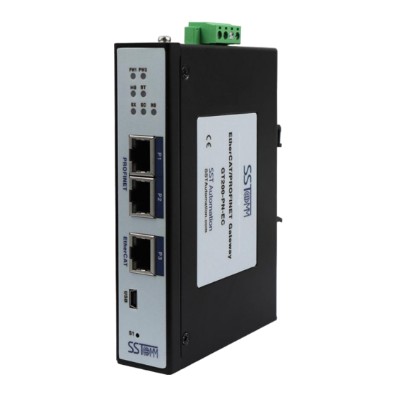
2 Hardware Overview 2.1 Product Layout Power Interface Ground Screw Power LED Indicators PROFINET Network LED Indicator BOOTLOADER LED Indicator Data Exchange LED Indicator PROFINET Network Communication LED Indicator EtherCAT Network Communication LED Indicator USB Mini-B Interface PROFINET Interface Reset Button EtherCAT Interface www.SSTAutomation.com... -
Page 11: Power Interface
2.2 Power Interface The GT200-PN-EC gateway features two power interfaces that are used to accept a 24VDC input voltage: a 5.08mm pitch screw terminal block and a 2.1mm DC barrel connector. The GT200-PN-EC can accept intput voltages between 12 to 36 VDC. Users can choose the power supply input interface that best fits their application. -
Page 12: Led Status Indicators
2.5 LED Status Indicators Indicator Status Description Solid Green PW1/PW2 Power supply is normal PROFINET network is normal One of the following conditions exists: • No physical connection detected on both of the 2 PROFINET ports. Solid Green • A drive on the network has generated an alarm. •... -
Page 13: Usb Mini-B Interface
GND, Signal Ground 2.7 Ground Screw The GT200-PN-EC features a ground screw that can be used to provide a chassis ground for the gateway. 2.8 RESET Button The RST button is used for firmware upgrades of the EtherCAT communication chip. Refer to Chapter 8.2... -
Page 14: Hardware Mounting
3 Hardware Mounting Hang the upper slot at the back of the gateway onto the upper hook of the guide rail, then press the gateway downward in the direction of the lower hook of the guide rail until it locks in place. www.SSTAutomation.com... -
Page 15: Getting Started - Quick Installation Guide
4 Getting Started - Quick Installation Guide 4.1 Hardware Installation 1. Securely attach the grounding wire to the grounding screw on the gateway to ensure a strong connection to ground. 2. Connect the EtherCAT interface of the gateway to the EtherCAT network of the servo drive. For more details about the EtherCAT interface, refer to Chapter 2.4. -
Page 16: Servo Drive Configuration
OP (operational) mode, remaining in this state continuously. It‘s important to note that GT200-PN-EC functions solely as a protocol converter and is not a debugging tool for EtherCAT drives. Before using the gateway for protocol conversion applications, it‘s recommended to debug the drives using the selected drive‘s upper-level software, addressing issues such as clearing drive alarms and configuring... -
Page 17: Drive Parameters
5.2 Drive Parameters The servo drive can be configured by modifying the drive parameters in TIA Portal. The following parameters are supported by the GT200-PN-EC gateway: Default Data Data PROFIdrive Units Parameter Parameter Value Value Value Type Access Telegrams Number... - Page 18 Parameters can be read and written to using the SinaParaS function block in TIA Portal. The location of the function block is shown in the figure below: www.SSTAutomation.com...
- Page 19 Axis number / axis ID in a multi-axis system Hardware ID of the module access points / HardwareID HW IO actual value telegram slot of the axis or drive Note: To read the parameters from the GT200-PN-EC, the value of AxisNo should be set to 1. www.SSTAutomation.com...
- Page 20 Output Signal Data Type Default Value Description Checkback signal: Ready BOOL 1 = Job ended or job canceled Current job status: Busy BOOL 1 = Job in progress Job completion: Done BOOL 1 = Job ended without errors ValueRead1 REAL Value of the read parameter in REAL format ValueRead2 DINT...
- Page 21 For example, to access the "Ramp Generator Slope" parameter using the SinaParaS function block, set the Parameter field to 100. The Index field is used to specify which axis to access (0 for the first axis, 1 for the second axis, etc.). The following diagram illustrates how to read and write this parameter to the second axis: www.SSTAutomation.com...
-
Page 22: Electronic Gear Ratio
5.3 Electronic Gear Ratio Load Revolutions Load Feed Travel (µm or °) Motor Revolutions The servo motor drive can be configured with an electronic gear ratio to electronically enlarge or reduce the travel distance of the load shaft relative to the motor shaft. The electronic gear ratio for the drive can be configured by modifying the Load Travel Distance (LU) per Motor Revolution [LU/rev] parameter in PROFIdrive Telegram 111 (which corresponds to V90 PN parameter p29247). - Page 23 The Position Factor is used to define the proportional relationship between the load travel distance (LU) per load LU per Motor Revolution = (LU per Load Revolution) × (Position Factor) revolution, and the load travel distance (LU) per motor revolution input parameter. [LU/Motor Rev] [LU/Load Rev] The Position Factor is related to the desired mechanical reduction ratio (gear ratio), mechanical dimensions related to...
-
Page 24: Epos Homing Method
To streamline user operations, for certain brands of drives the GT200-PN-EC gateway automatically configures the electronic gear ratio settings for the drive based on the gear ratio information set by the user during configuration. However, for some drive brands, the electronic gear ratio configuration needs to be done using the manufacturer's drive controller software and saved to the drive. - Page 25 Because of this variance, the GT200-PN-EC does not enforce a specific homing method when using the SINA_POS function block for drive homing. Instead, it leaves the decision of which homing method to use to the user. If Siemens...
-
Page 26: Servo Drives With Special Settings
5.5 Servo Drives with Special Settings 5.5.1 Panasonic To simplify the connection to EtherCAT servos , the GT200-PN-EC standardizes the PDO mapping when connecting to servos. However, since Panasonic servos do not support dynamic PDO mapping, the servo needs to be manually configured in the manufacturer’s drive controller software to connect to the GT200-PN-EC. - Page 27 3. Enter the configuration settings for each RPDO and TPDO exactly as shown in the red boxes in the diagram below. Then click the "EEP" button to save the settings to the drive. After configuring, restart the drive for the changes to take effect.
-
Page 28: Yaskawa
5.5.2 YASKAWA To manually set the position gear ratio, speed gear ratio, and acceleration gear ratio parameters using the Yaskawa drive controller software, follow the instructions outlined in the steps below: 1. Import the model file for the Yaskawa Σ-7S series EtherCAT drive using the Yaskawa drive controller software SigmaWin+ Ver.7, then reopen the software to connect to the drive. - Page 29 3. Configure the following parameters in the Yaskawa drive controller software: Set 2701h-01, 2702h-01, and 2703h-01 as the numerator of the electronic gear ratio. Set 2701h-02 and 2702h-02 as the denominator of the electronic gear ratio. (denominator of the electronic gear ratio) × 10000. Set 2703h-02 with the following formula: After entering the settings, save the new configuration to the drive.
-
Page 30: Servotronix
The Servotronix BDHDE drive has two different response modes for responding to SDO commands: normal mode and fast mode. When connecting to the GT200-PN-EC, the Servotronix drive needs to be switched to fast mode. 1. Connect to the drive using the ServoStudio 2 drive controller software. -
Page 31: Hiwin
2. Open the command terminal interface, enter the command 'ecml 1' and press Enter. Then, enter the command 'ecml' to confirm if it is set to 1. If it is 1, save it to the drive, and restart the drive to apply the changes. 5.5.4 HIWIN To manually set the electronic gear ratio parameters for HIWIN E1 series drives using the drive controller software, follow the instructions outlined in the steps below:... -
Page 32: Plc Project Configuration
This manual takes the example of using Siemens 111 messages with an S7-1511 PLC to control 6 EtherCAT bus drives through GT200-PN-EC, explaining the project configuration steps for the PLC. This project is based on TIA Portal V17, and there may be slight differences in other versions. - Page 33 2. Install the GSDML file for GT200-PN-EC. www.SSTAutomation.com...
- Page 34 3. Add the GT200-PN-EC device and establish a network connection with the PLC. The GSDML file for GT200-PN-EC is located in the hardware directory at the following path. Add GT200-PN-EC to the network view. Note: Make sure to select the correct GSDML version, as shown in the diagram.
- Page 35 4. Set the IP address and device name for both S7-1511 and GT200-PN-EC separately. www.SSTAutomation.com...
- Page 36 In the device properties, set the communication cycle for GT200-PN-EC. The default communication cycle is 2ms. If you wish to modify it, select the checkbox below to set it manually. www.SSTAutomation.com...
- Page 37 5. In the device view of GT200-PN-EC, insert the PROFINET Module from the right side six times (default to use Siemens 111 messages, can be replaced with other messages ). Each module corresponds to one EtherCAT bus drive, and the order of module insertion corresponds to the cascade order of EtherCAT drives.
- Page 38 If set to an incremental Encoder Type encoder, the corresponding drive needs to complete homing before absolute positioning can be performed (the homing flag is stored in GT200-PN-EC and is not saved; the flag disappears when GT200-PN-EC loses power). Reference Speed This parameter is the reference speed corresponding to the motor.
- Page 39 6. Drag the SINA_POS(FB284) function block into the programming network in OB1 Note: Refer to the following diagram for the assignment of the pin values for HWIDSTW and HWIDZSW in the function block. www.SSTAutomation.com...
- Page 40 7. In TIA Portal V17 version, the "Basic Positioning Axis" function block has been added, allowing users to conveniently configure mechanical parameters using process objects. With the introduction of six basic positioning axis function blocks, six corresponding process objects for basic positioning axes will be added to the left-side process object bar.
- Page 41 Set the respective process object axis forms. Associate the process object axis with the modules during configuration. www.SSTAutomation.com...
- Page 42 Configure the mechanical parameters of the process object axis based on the actual mechanical connections. www.SSTAutomation.com...
-
Page 43: Sina_Pos Function Block
The SINA_POS function block in TIA Portal can be used for basic positioner control of the drive. Using GT200-PN-EC is equivalent to adding basic positioner (EPOS) functionality to each EtherCAT bus drive. The main operating modes include Jog, Homing, MDI, and program segment. - Page 44 DriveLib: www.SSTAutomation.com...
- Page 45 TIAPortal V17 Built-in Library: The function block can be called in either of the following organization blocks (OB): • Cycle organization block: OB1 • Cyclic interrupt organization block: such as OB32 www.SSTAutomation.com...
- Page 46 Negative direction Jog1 BOOL Jog signal 1 Jog2 BOOL Jog signal 2 FlyRef BOOL The input is not valid for GT200-PN-EC AckError BOOL Reset from error ExecuteMode BOOL Activate requested mode Position setting value when ModePos=1 or 2 Position DINT 0[LU] Program segment no.
- Page 47 Note: If this parameter is assigned a variable in the program, the initial value must be 3 (i.e.,ConfigEPos.%X0 and ConfigEPos.%X1must be equal to 1. If not activated, OFF2 and OFF3 stops will always be effective). Hardware ID of message 111 in the GT200-PN-EC device HWIDSTW HW_IO view...
- Page 48 Data Output Signal Default Value Description Type AxisEnabled BOOL The driver is enabled AxisPosOk BOOL Target positon arrived AxisSpFixed BOOL Setting position arrived AxisRef BOOL Reference point is set AxisWarn BOOL Warning of driver AxisError BOOL Error of driver The driver is in the disabled state. Check if the bits 0 and 1 of the Lockout BOOL...
-
Page 49: Operation Modes Of The Function Block
7.3.2 Relative Positioning Mode The Relative Positioning Mode can be performed through the drive's relative positioning function. The PLC activates the internal position controller of the EtherCAT bus drive through the GT200-PN-EC to perform relative position control. Requirements: •... - Page 50 Steps: 1. Specify the target position and velocity through input parameters Position and Velocity. 2. Specify the percentage of speed, acceleration, and deceleration through input parameters OverV, OverAcc, and OverDec. 3. CancelTraversing and IntermediateStop must be set to 1, and Jog1 and Jog2 must be set to 0. 4.
-
Page 51: Absolute Positioning Mode
7.3.3 Absolute Positioning Mode The Absolute Positioning Mode can be performed through the drive's absolute positioning functionality. The PLC activates the internal position controller of the EtherCAT bus drive via the GT200-PN-EC to perform absolute position control. Requirements: • Select operating mode ModePos=2 •... -
Page 52: Constant Velocity Mode
The control timing is as shown in the following diagram: EnableAxis ExecuteMode Relative Absolute ModePos = 1, 2 AxisPosOK 7.3.4 Constant Velocity Mode The Constant Velocity Mode allows the axis to run at a constant speed in the forward or reverse direction. Requirements: •... - Page 53 Steps: 1. Specify the target velocity through the Velocity input parameter. 2. Specify the percentage of speed, acceleration, and deceleration through input parameters OverV, OverAcc, and OverDec. 3. CancelTraversing and IntermediateStop must be set to 1, and Jog1 and Jog2 must be set to 0. 4.
-
Page 54: Active Homing Mode
7.3.5 Active Homing Mode This function allows the axis to perform homing operation based on the preset homing method configured, activating the drive's active homing. Requirements: • Select operating mode ModePos=3 • Axis enable, EnableAxis=1 • The homing switch is connected to the designated digital input point on the drive.36 Steps: 1. -
Page 55: Calibrate Home Position Mode
7.3.6 Calibrate Home Position Mode This operating mode allows the axis to set the zero position at any position. Requirements: • Select operating mode ModePos=5 • The axis must be in the enabled state and in a stationary state during execution. Steps: 1. -
Page 56: Velocity Jog Mode
7.3.7 Velocity Jog Mode The Velocity Jog Mode is implemented through the Jog operation function of the drive. Requirements: • Select operating mode ModePos=7 • Axis enable, EnableAxis=1 • The axis must be in a stationary state. • The axis does not need to be homed, or the absolute value encoder can be in an uncalibrated state. Steps: 1. -
Page 57: Position Jog Mode
7.3.8 Position Jog Mode The Position Jog Mode is implemented through the Jogging function of the drive. Requirements: • Select operating mode ModePos=8 • Axis enable, EnableAxis=1 • The axis must be in a stationary state. • The axis does not need to be homed, or the absolute value encoder can be in an uncalibrated state. Steps: 1. -
Page 58: Operating Mode Switching Instructions Based On Modepos
7.4 Operating Mode Switching Instructions Based on ModePos The following diagram illustrates potential operational mode transitions based on the ModePos value: www.SSTAutomation.com... -
Page 59: Expanding Ethercat Bus Io
8 Expanding EtherCAT Bus IO Currently, GT200-PN-EC supports up to 16 drives, but many installations may only require a few drives, along with some EtherCAT bus IO devices such as flow meters, sensors, integrated IO, etc. To facilitate the integration of these devices into the PROFINET bus system, GT200-PN-EC has added the capability to carry EtherCAT IO devices. - Page 60 7. Right-click on the position of Subslot 2 and delete the Siemens 111 telegram. www.SSTAutomation.com...
- Page 61 Next, insert the "IO Telegram" module from the right-hand side submodule into Subslot 2. www.SSTAutomation.com...
-
Page 62: Function Description
(inverter, servo, etc.), and the gateway will perform internal conversion between PROFIdrive and DS402. If an IO Telegram submodule is inserted into slot 2, GT200-PN-EC will treat the corresponding EtherCAT device as an IO device (flow meter, sensor, integrated IO, encoder, etc.), and the gateway will not process the data internally but will pass it through.
Need help?
Do you have a question about the GT200-PN-EC and is the answer not in the manual?
Questions and answers