Table of Contents
Advertisement
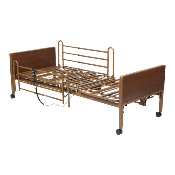
DRIVE COMPETITOR II SEMI ELECTRIC BED
Model # 15561 / 15561FR / 15561HR / 15571 / 15571FR / 15571HR
OWNER'S ASSEMBLY AND OPERATING MANUAL
This manual must be given to the Owner/User of this bed and
should be read carefully before putting this product into use.
Keep manual in an accessible location for future reference.
15561/15571 Series Manual REV1.1.29.18
Item # 15571FR with Full Side Rails
Item # 15561HR with Half Rails
Advertisement
Table of Contents

Related Manuals for Drive 15561


Summary of Contents for Drive 15561
- Page 1 DRIVE COMPETITOR II SEMI ELECTRIC BED Model # 15561 / 15561FR / 15561HR / 15571 / 15571FR / 15571HR OWNER’S ASSEMBLY AND OPERATING MANUAL Item # 15571FR with Full Side Rails Item # 15561HR with Half Rails This manual must be given to the Owner/User of this bed and should be read carefully before putting this product into use.
-
Page 2: Table Of Contents
TABLE OF CONTENTS Standard Symbols & Warning Labels ....................1-3 Intended Use & General Safety ......................4-6 Electromagnetic Emmissions & Immunity ..................7-10 Technical Specifications ........................11 Packaging and Handling ........................12 Unpacking ............................12 Inspection ............................13 Storage ............................13 Assembly Instructions ......................... -
Page 3: Standard Symbols & Warning Labels
STANDARD SYMBOLS USED IN THIS MANUAL This manual includes important information about the safety of personnel and equipment. As you read through this manual be aware of the symbols and their meanings. DANGER Information that appears under the DANGER symbol concerns the protection of personnel from direct and pending hazards that, if not avoided, will result in immediate, serious personal injury or death in addition to damage of the equipment. - Page 4 PRODUCT SYMBOLS Symbols Description Symbols Description Type BF applied part equipment. Recycle the item in accor- IEC 60601-2-52: The applied part includes all dance with local regulations. parts of the medical bed that are within reach of the patient, even if they are underneath the mattress support surface.
- Page 5 WARNING LABELS...
-
Page 6: Intended Use & General Safety
• DO NOT operate this product without first reading and understanding this user manual. Damage or injury may result from improper use of this product. • Possible injury or Death may occur if accessories are not provided by Drive DeVilbiss Healthcare. Please contact Drive DeVilbiss Healthcare for accessories that are compatible with this bed. - Page 7 This bed should not be placed in an oxygen enriched environment. CAUTION • This medical bed is not intended to work with patient lifts other than those specified by Drive DeVilbiss Healthcare as being compatible. • Do NOT use side rails as handles for moving the bed.
- Page 8 A mattress may not be included with this bed. It is recommended that a standard 36” wide mattress that is made to fit an 80”or 84” (extension) length bed frame is used, such as a Drive DeVilbiss Healthcare standard inner spring, foam, fiber, or pressure redistribution mattress.
-
Page 9: Electromagnetic Emmissions & Immunity
ADJUST, including cables specified by the manufacturer. Otherwise, degradation of the performance of this equipment could result.” The use of accessories and cables other than those specified by Drive DeVilbiss Healthcare, with the exception of accessories and cables sold by Drive DeVilbiss Healthcare for use with the SEMI ELECTRIC BED WITH MANUAL LEG ADJUST as replacement parts for internal components, may result in increased EMISSIONS or decreased IMMUNITY of the SEMI ELECTRIC BED WITH MANUAL LEG ADJUST. - Page 10 EMI COMPLIANCE TABLE Table 1 - Emisson Phenomenon Compliance Electromagnetic environment RF emissions CISPR 11 Professional healthcare facility environment and Group 1, Class B homecare environment Table 2 - Enclosure Port Phenomenon Basic EMC standard Immunity test levels Professional healthcare facility environment and homecare environment Electrostatic IEC 61000-4-2...
- Page 11 Table 4 - Input AC power Port Phenomenon Basic EMC standard Immunity test levels Professional healthcare facility environment and homecare environment Electrical fast IEC 61000-4-4 ±2 kV transients/burst 100kHz repetition frequency Surges IEC 61000-4-5 ±0.5 kV, ±1 kV Line-to-line Conducted disturbances IEC 61000-4-6 3V, 0.15MHz-80MHz induced by RF fields...
- Page 12 ELECTRICAL SAFETY WARNINGS A safety feature of this product includes protection against overheating caused by excessive or extended periods of operation. Depending on the duration, this includes multiple or repeated adjustments or the use of multiple functions at one time. To ensure trouble free operation, always allow a slight pause between multiple adjustments and avoid pressing more than one function button at a time.
-
Page 13: Technical Specifications
Operating Temperature range of 41°F to 104°F before use. BED SERIAL NUMBERS When ordering parts or when contacting Drive DeVilbiss Healthcare Customer Service Department, please include bed’s model and serial numbers, found on the identification labels as below. The identification labels are located under the sleep deck on the either side of the bed frame. -
Page 14: Packaging And Handling
UNPACKING 1. Check cartons for any obvious damage to packaging or contents. If damage is evident, contact your local Drive Medical dealer/provider. 2. Remove any loose packaging from the cartons. -
Page 15: Inspection
INSPECTION 1. Examine each component carefully for damage, scratches, dents or any other visual damage. 2. Carefully remove Tie Wraps holding power cord, hand pendant and drive shaft. 3. Inspect power cord and plug for cuts or damage. 4. Inspect the motors for damage, loose connections, cuts or damage to the wires. -
Page 16: Assembly Instructions
D. Casters (4) – 2 locking, non-locking (15571 Series Only) E. Hand Crank (15571 Series Only) F. Hi/Low Drive Shaft (15571 Series Only) G. Head/Foot Deck Section Motors with Hand Control Caution: DO NOT attempt to operate bed controls until completion of assembly as damage to bed components and/or... -
Page 17: Frame Assembly
FRAME ASSEMBLY Place both ends of the frame/sleep surface on their side and align the flange with the receptacle as shown. - Page 18 To attach the head and foot sections, slide the two sides together and lock into position with cotter pin and clasp. To disassemble the head and foot section, remove cotter pin and clasp and seperate sections.
- Page 19 Secure the frame/sleep surface with the cotter pin as shown (Figure A). Lock the cotter pin with the attached clasp. Repeat on the opposite side (Figure B). Figure A Figure B...
-
Page 20: Motor Installation
THERE ARE TWO METHODS FOR THE INSTALLATION OF THE MOTOR NOTE: Before installing motor, ensure plug hand pendant cable is plugged into motor as shown To install motor, remove locking caps on top of the motor. METHOD A The motor is installed on the bed frame when the frame is standing on its side. -
Page 21: Method A - Side Installation
METHOD A Installation of the motor when bed frame is on its side A1. Prior to installation, make sure that the 2 white motor blocks are in the retracted position. If the white motor block is not in the retracted position, plug power cord into power outlet and retract motor block by depressing the down buttons on hand pendant until motor block is fully retracted. - Page 22 A6. Once in place, replace the motor covers to secure the motor. A7. Assemble Bed Ends to Frame: #15571HF for Crank Hi/Lo Beds Ends or #15561HF for Manual Adjustment Bed Ends. Once the motor is attached, lay bed flat and install head and foot boards. Foot end of the bed frame has the mattress retainer.
- Page 23 Slide Driveshaft under length of the bed. Lift the Head Section of the bed frame and install the Spring Loaded end of the Hi/Lo Drive Shaft to the Foot Board drive pin, then install head end of the Hi/Lo Drive Shaft to the Head Board drive pin.
-
Page 24: Method B - Underneath Installation
Gear box crank connection will always face outward – away from the bed. B2. The #15571 Hi/Lo Drive Shaft comes in 3 sections. Assemble the Hi/Lo Drive Shaft by inserting the (A) section with push pin into the (B) section with indicators and align with the “Semi” indicator hole. Next extend the (C) section and... - Page 25 For 15571, slide Driveshaft under length of the bed. Lift the Head Section of the bed frame and install the Spring Loaded end of the Hi/Lo Drive Shaft to the Foot Board drive pin, then install head end of the Hi/Lo Drive Shaft to the Head Board drive pin.
- Page 26 B5. With both hands, lift the motor and insert into the actuator and frame as shown. With the palm of your hand snap the motor flush to actuator bar. B6. Once in place, replace the motor covers to secure the motor by sliding cover over motor guides to secure the actuator bar.
-
Page 27: Bed Operation
When routing cables from other equipment in the medical bed, precautions shall be taken to avoid squeezing between parts of the medical bed. OPERATION The Model #15571 & 15561 Semi-Electric Bed comes with a 3 Function hand held Pendant. • Top Buttons control raising and lowering the Head Section;... - Page 28 Battery function should be checked periodically to insure battery health. The battery should be removed if it no longer has a charge or if leakage from battery occurs. • Drive DeVilbiss Healthcare cannot be held responsible for improper backup use. • When battery is installed, unplugging the bed from mains power will not switch bed off.
-
Page 29: Bed Rail Installation
SIDE RAIL INSTALLATION (OPTION) SIDE RAIL WARNING Other manufacturers side rails/bars may not be compatible and can lead to entrapment issues or harm to patients/ residents. Only compatible side rails/bars may be used on this bed. Make sure bed frame is adjusted correctly for mattress size being used and side rails/bars are properly secured to frame to decrease the risk of entrapment. - Page 30 The FDA Guidance document identifies specific dimensional criteria on potentially injury-threatening gaps and spaces that can occur between bed system components, such as side rails when improperly installed. Drive DeVilbiss Healthcare’s 15561/15571 beds and approved accessories are manufactured to be in conformance with these guidelines.
- Page 31 Half Bed Rails: To install half rails, locate the label located on the head section of the frame (Fig D). The half rail clamp should be installed over this label. Align fixed clamp jaw (Fig E) in front of bed frame rail as shown below. Align movable clamp jaw on top of bed frame rail, and turn knob clockwise until clamp is tight, securing safety rail to bed frame rail (Fig F).
-
Page 32: Manual Hi/Lo Adjustment Crank & Manual Leg Adjustment
MATTRESS RETAINER ADJUSTMENT Before a mattress is placed onto the bed deck, flip up the mattress guard to reduce mattress movement 15571HF HI/LO ADJUSTMENT CRANK Use hand crank to raise or lower the entire bed. Insert Hand Crank into bed end gear box and turn to adjust bed height. - Page 33 15561 MANUAL ADJUST HEAD & FOOT BOARDS #15561HF Manual Adjust Head & Foot Boards have two height adjustments. Adjustment #1 is located on the bed end frame that allows for an upper and lower deck height position. Adjustment #2 is located on the Bed End leg itself and allows for High, Medium and Low Leg Height positions.
-
Page 34: Accessories
Four (4) 3” Casters #15561EXT: 4” Bed Length Extender (For both 15561 & 15571 beds): 1. Detach Drive Shaft from bed ends, attach extension and put aside (Model #15571 only) 2. Detach Foot Bed End 3. Attach Bed Deck extension to foot section of bed deck and secure with bolts. - Page 35 #15571TRANS: Transporter (for 15571) #15561TRANSC: Transporter with std 3” Casters (For 15561) #15571TRANS Transporter (for 15571) Installation: 1. Completely disassemble bed 2. Assemble bed ends to each side of transporter deck 3. Assemble motor to foot end mounting pins 4. Place Head and Foot Frame onto Transporter Deck #15561TRANSC: Transporter with Casters (For 15561) Installation: 1.
-
Page 36: Maintenance & Safety Checks
• 1 year warranty on all other parts and components. During the warranty period, defective items will be repaired or replaced at Drive’s option at no charge. NOTE: The Competitor II bed can be used with a free standing trapeze or a Drive Medical frame mounted trapeze (Item# 13009KT-BV). - Page 37 A majority of service requests can be handled by the local Distributor/Provider’s maintenance department with assistance from Drive DeVilbiss Healthcare tech support. If a Drive DeVilbiss Healthcare technician is required, one will be provided by Drive DeVilbiss Healthcare at our discretion.
-
Page 38: Warnings
Keep all moving parts, including the main frame, mattress deck (head and foot sections) and all drive shafts free of Check all parts for shipping damage and test before using. obstruction (i.e. blankets/sheets, heating blankets/pads, In case of damage, DO NOT use. -
Page 39: Warnings
Mattress MUST fit bed frame and side rails snugly to qualified technician. reduce the risk of entrapment. The total weight limit of the Drive Medical 36 inch (91.4cm) When operating this bed, ALWAYS ensure that the wide Manual/Semi-Electric/Full Electric bed is 450 pounds individual utilizing the bed is positioned properly within the confines of the bed. -
Page 40: Troubleshooting
Raise and Lower 2. Ensure Hand Crank is properly engaged into bed end gear box. 3. Drive Shaft may not be installed or is incorrectly installed. Ensure Drive Shaft is properly connected to both Bed End gear boxes. 4. To work properly, Bed Ends must be installed as a set: Bed End at Head Section will say “HEAD”... -
Page 41: Appendix: A Guide To Bed Safety Bed Rails
APPENDIX SPECIAL NOTE For your convenience, we have provided the April 2010 edition of the FDA’s guide to bed safety. This information from the FDA’s brochure, published by Hospital Bed Safety Workgroup, is replicated verbatim; the latest version is available at http://www.fda.gov. - Page 42 • Anticipate the reasons patients get out of bed such as hunger, thirst, going to the bathroom, restlessness and pain; meet these needs by offering food and fluids, scheduling ample toileting, and providing calming interventions and pain relief. When bed rails are used, perform an on-going assessment of the patient’s physical and mental status; closely monitor high-risk patients.
- Page 43 99 Seaview Boulevard Port Washington, NY 11050 Phone: 516-998-4600 Toll Free: 877.224.0946 Fax: 516.998.4601 www.drivemedical.com 15561/15571 Series Manual REV1.09.14.17...
Need help?
Do you have a question about the 15561 and is the answer not in the manual?
Questions and answers