
Related Manuals for Canon W6200


Summary of Contents for Canon W6200
- Page 1 REVISION 0 AY3-4308-002 OCT. 2003 COPYRIGHT 2003 CANON INC. CANON W6200 N 1003 0.00-0 PRINTED IN JAPAN (IMPRIME AU JAPON)
- Page 2 1003 N 0.00-0...
- Page 4 U n d e r t h e c o p y r i g h t l a w s , t h i s manual may not be copied, re p roduced, or translated into other languages, in whole or in part, without the express written consent of Canon Inc. except in the case of intern a l business use.
- Page 5 I. ABOUT THIS MANUAL This manual is divided into five parts containing the information required for servicing the W8200 printer. Part 1: Safety and Precautions This part contains information on how to service the unit safety. It is very important, and must be read. Part 2: Product Specifications This part outlines the product and its specifications.
-
Page 6: Table Of Contents
II. TABLE OF CONTENTS Part 1: SAFETY AND PRECAUTIONS Page 1 - 1 1. SAFETY PRECAUTIONS 1 - 1 Moving Parts 1 - 2 1 - 2 1.2.1 Ink passages 1 - 4 1.2.2 Ink mist 1 - 5 Electrical Parts 1 - 6 2. - Page 7 Part 3: OPERATING INSTRUCTIONS Page 3 - 1 1. NAMES AND FUNCTIONS OF COMPONENTS 3 - 1 Names and Functions of Components 3 - 1 1.1.1 Front 3 - 2 1.1.2 Rear 3 - 2 1.1.3 Carriage unit 3 - 3 1.1.4 Internal part 3 - 4 2.
- Page 8 Page 4 - 8 Power Off 4 - 8 2.2.1 Power Off sequence 4 - 9 Print Control 4 - 9 2.3.1 Print mode 4 -10 Print Position Adjustment 4 -10 2.4.1 Print position adjustment 4 -11 Overheating Protection Control of Printhead 4 -11 Pause between Pages 4 -11...
- Page 9 Part 5: MAINTENANCE Page 5 - 1 1. MAINTENANCE 5 - 1 List of Regular Replacement Parts 5 - 1 List of Consumables 5 - 1 List of Regular Maintenance 5 - 2 2. SERVICE TOOLS 5 - 2 List of Tools 5 - 3 Using the Cover Switch Tool 5 - 4...
- Page 10 Page 5 -47 7.2.6 No full bleed (W01022) 5 -47 7.2.7 W01030/W01031/W01032/W01033/W01034/W01035/W01036/ W01037/W01038/W01039: GARO W0103x (number is indicated by x) 5 -48 Troubleshooting When Errors Occur 5 -48 7.3.1 E02000 Roll media end error 5 -48 7.3.2 E0200D/E02016 Cut sheet end error 5 -49 7.3.3 E0200A/E0200B/E0200C/E0200E/E0200F/E02010/E02017/E02018...
- Page 11 Page 5 -61 7.3.25 E02F00 System controller internal error 5 -62 Troubleshooting When Service Call Errors Occur 5 -62 7.4.1 Printhead error! (E04000) 5 -63 7.4.2 Scale read error! (E04002) 5 -63 7.4.3 Turn Power Off!! (S04010/S04011/S04012) 5 -64 7.4.4 Turn Power Off!! (E02777) 5 -65...
- Page 12 III. ILLUSTRATION INDEX Part 1: SAFETY AND PRECAUTIONS Page 1 - 1 Figure 1- 1 Moving Parts of the Printer 1 - 3 Figure 1- 2 Ink Passages 1 - 4 Figure 1- 3 Ink Mist 1 - 5 Figure 1- 4 Electrical Parts 1 - 6 Figure 1- 5...
- Page 13 Page 3 -34 Figure 3- 29 LF ACCURACY (Image) 3 -53 Figure 3- 30 com_fut.exe (Startup) 3 -53 Figure 3- 31 com_fut.exe (Setup 1) 3 -54 Figure 3- 32 com_fut.exe (Setup 2) 3 -54 Figure 3- 33 com_fut.exe (Send Image) 3 -54 Figure 3- 34 com_fut.exe (Transmission is completed)
- Page 14 Part 5: MAINTENANCE Page 5 - 3 Figure 5- 1 Using the Cover Switch Tool 5 - 4 Figure 5- 2 Applying the grase of carriage 5 - 4 Figure 5- 3 Applying the grease of pinch roller unit 5 - 5 Figure 5- 4 Applying the grease of feed roller 5 - 5...
- Page 15 I V. TABLE INDEX Part 4: TECHNICAL REFERENCE Page 4 -10 Table 4- 1 PRINT MODES 4 -24 Table 4- 2 SIGNALS AND PIN NUMBERS OF THE SIGNAL CONTACT POINTS...
- Page 16 This page is intentionaly left blank...
-
Page 17: Part 1: Safety And Precautions
Part 1 SAFETY AND PRECAUTIONS Page 1 - 1 1. SAFETY PRECAUTIONS 1 - 1 1.1 Moving Parts 1 - 2 1.2 Ink 1 - 5 1.3 Electrical Parts 1 - 6 2. OTHER PRECAUTIONS 1 - 6 2.1 Printhead 1 - 8 2.2 Ink tank 1 - 9... -
Page 18: Safety Precautions
W6200 Part 1: Safety and Precautions 1. SAFETY PRECAUTIONS 1.1 Moving Parts Be careful not to get your hair, clothes, or accessories caught in the moving parts of the printer. These include the carriage unit, carriage belt, ink tube and flexible cable activated by the carriage motor;... -
Page 19: Ink
Part 1: Safety and Precautions W6200 1.2 Ink 1.2.1 Ink passages Be careful not to touch the ink passages of the printer or to allow ink to stain the workbench, hands, clothes or the printer under repair. The ink flows through the ink tank unit, carriage unit, purge unit, maintenance-jet tray maintenance cartridge and the ink tubes that relay ink to each unit. - Page 20 W6200 Part 1: Safety and Precautions Maintenance-jet tray Carriage unit Maintenance cartridge Ink tank unit Purge unit Figure 1-2 Ink Passages...
-
Page 21: Ink Mist
Part 1: Safety and Precautions W6200 1.2.2 Ink mist Since the printhead prints by squirting ink onto the media, a minute amount of ink mist is generated in the printing unit during printing. The ink mist is collected in the printer by the airflow. -
Page 22: Electrical Parts
W6200 Part 1: Safety and Precautions 1.3 Electrical Parts The electrical unit of the printer is activated when connected to the AC power supply. At the rear of the printer are the system controller, engine controller, power supply and interface connector. The head relay PCB and carriage relay PCB are incorporated in the carriage unit, and the operation panel is located on the upper right cover. -
Page 23: Other Precautions
Part 1: Safety and Precautions W6200 2. OTHER PRECAUTIONS 2.1 Printhead 2.1.1 How to handle the printhead Do not open the printhead package until you are ready to install the head. When installing the printhead in the printer, hold the knob, and then remove the protective material and protective cap, in that order. -
Page 24: Capping
W6200 Part 1: Safety and Precautions 2.1.2 Capping The printer will perform the capping operation when printing has finished or during standby due to errors, in order to protect the printhead and avoid ink leakage. If the power cord is accidentally unplugged, turn the power button off, reconnect the power cord, and turn the power button on to confirm that the printer starts up properly and changes to the “Online”... -
Page 25: Ink Tank
Part 1: Safety and Precautions W6200 2.2 Ink Tank 2.2.1 Opening the ink tank Do not open the ink tank until ready to use. To prevent foreign matter from entering the ink supply unit, install the opened Ink tank immediately. -
Page 26: Handling The Printer
W6200 Part 1: Safety and Precautions 2.3 Handling the Printer 2.3.1 Precautions against static electricity Certain clothing may generate static electricity, causing an electrical charge to build up on your body. Such a charge can damage electrical devices. In particular, never touch the printhead contacts. -
Page 27: Fixing The Carriage
Part 1: Safety and Precautions W6200 2.3.2 Fixing the carriage After printing, the carriage caps the printhead and uses the lock arm inside the purge unit to apply a mechanical lock. When transporting the printer, use belt stoppers to secure the carriage at the carriage home position so that the carriage does not become separated from the lock arm. -
Page 28: Replacing The Maintenance Cartridge
W6200 Part 1: Safety and Precautions 2.3.3 Replacing the maintenance cartridge When the maintenance cartridge detects that tank is full, the "Replace MT cartridge" error appears. In this case the maintenance cartridge must be replaced. The printer will not operate until the error is canceled. -
Page 29: Precautions When Servicing The Printer
Part 1: Safety and Precautions W6200 3. PRECAUTIONS WHEN SERVICING THE PRINTER 3.1 Stored Data This printer counts the printing length, number of ink tank replacements, carriage driving time, number of cleanings, and the cutter usage, and stores this information in the system controller EEPROM (IC36) and in the engine controller EEPROM (IC421) as the service mode counter. -
Page 30: Firmware Confirmation
W6200 Part 1: Safety and Precautions 3.2 Firmware Confirmation Firmware has been downloaded to each of a System Controller and Engine Controller. When replacing each board with the one with Service Parts, confirm that each firmware is the latest version. If it is not the latest version, please update it to the latest version. -
Page 31: Part 2: Product Specifications
Part 2 PRODUCT SPECIFICATIONS Page 2 - 1 1. PRODUCT OVERVIEW 2 - 1 1.1 Product Overview 2 - 2 1.2 Features 2 - 3 1.3 Printhead 2 - 3 1.4 Ink Tank 2 - 4 1.5 Cutter Unit 2 - 4 1.6 Roll holder 2 - 5 1.7 Consumables... -
Page 32: Product Overview
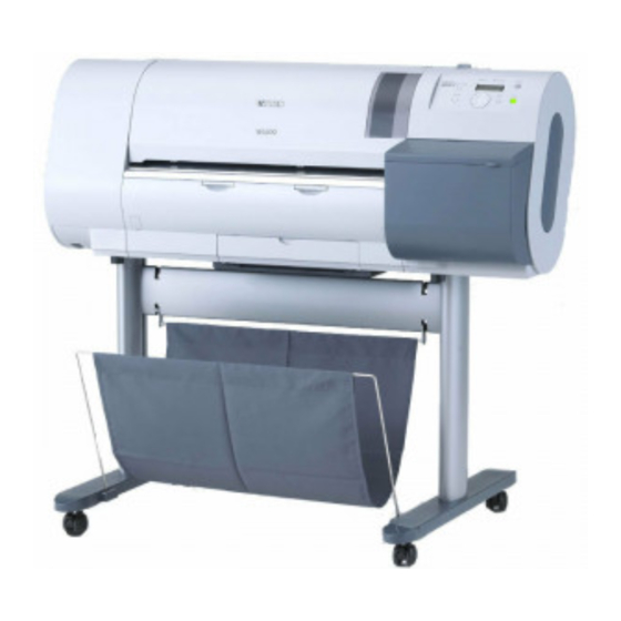
W6200 Part 2: Product Specifications 1. PRODUCT OVERVIEW 1.1 Product Overview This printer is a large format printer which is capable of high-speed, photo-quality printing on large-size paper up to 24 inches wide. The printer is a desktop type. The printer is capable of output to either roll media or cut sheet. -
Page 33: Features
Part 2: Product Specifications W6200 1.2 Features • Light and compact body made possible by rear feeding of roll media. • Four-sides borderless printing support (roll media) eliminates tedious cutting and simplifies poster creation. • High quality photo finish with 1200 x 1200 dpi maximum resolution using highly lightfast, water-proof, and ozone-proof six color (C, M, Y, Bk, PC, PM) pigment ink. -
Page 34: Printhead
W6200 Part 2: Product Specifications 1.3 Printhead On the carriage, disposable printhead is installed, each of which contains six rows of integrated nozzles. Each row consists of 1280 nozzles, which are arranged in a staggered pattern for printing efficiency. If print quality does not improve despite carrying out cleaning, the printhead should be replaced with a new one. -
Page 35: Cutter Unit
Part 2: Product Specifications W6200 1.5 Cutter Unit A disposable cutter unit is mounted on the carriage. When the cutter becomes dull, increment the position adjustment dial by 1. If the dial is at 3, replace with a new cutter unit. -
Page 36: Consumables
W6200 Part 2: Product Specifications 1.7 Consumables 1.7.1 Printhead This consumable printhead is the same as the printhead shipped with the printer. The filters are included with the printhead and they should be replace before the printhead when replacing the printhead. -
Page 37: Specifications
Part 2: Product Specifications W6200 2. SPECIFICATIONS 2.1 General Specifications 1. Type W6200: Bubble jet printer (Desktop type) 2. Feeding system Roll media: Manual (rear setting) Cut sheet: Manual (front setting) 3. Feeding capacity Roll media: 1 roll (outer diameter: 130mm or less) Standard roll holder (provided with the product): inner diameter of the paper tube: 50.8mm (2”) - Page 38 W6200 Part 2: Product Specifications 9. Media size Media Width Length Roll media* 297.0mm (11.69”)* to 609.6mm (24”)* 210.0mm (8.27”)* to 18m (708.66”) Cut sheet 203.3mm (8”)* to 609.6mm (24”)* 203.3mm (8”)* to 914.4mm (36”)* Outer diameter of roll:130mm or less.
- Page 39 Part 2: Product Specifications W6200 13. Emulation None 14. Interface Network 10 Base-T/100 Base-TX (compliance with IEEE802.3 standards) Compliance with USB specification 2.0 standards (option) Compliant with IEEE1394-1995 standards and P1394a (Version2.0) (option) 15. Printhead/Ink Tank Printhead and separate ink tanks...
- Page 40 W6200 Part 2: Product Specifications 16. Detection functions Paper detection : Yes Paper leading and trailing edge detection : Yes Paper width detection : Yes Skew detection : Yes Paper slip detection : Yes Carriage position detection : Yes Carriage home position detection : Yes...
-
Page 41: Interface Specifications
Part 2: Product Specifications W6200 2.2 Interface Specifications 2.2.1 Network 1) Interface format Interface complying with IEEE802.3 standards 2) Data transfer 10Base-T/100Base-TX 3) Signal level Input : threshold 10 Base-T : max +585mV min +300mV 100 Base-TX : turn-on +1000mV diff pk-pk... -
Page 42: Usb (Option)
W6200 Part 2: Product Specifications 2.2.2 USB (option) 1) Interface format USB 2.0, Full Speed (12Mbit/sec), High Speed (480Mbit/sec) 2) Data transfer Control transfer Bulk transfer 3) Signal level Input: Input sensitivity difference: +0.2 V (Max.) Common mode difference: +0.8 V to +2.5 V Output: Static output High: +2.8 V to +3.6 V... -
Page 43: Ieee1394 (Option)
Part 2: Product Specifications W6200 2.2.3 IEEE1394 (option) 1) Interface format Interface complying with IEEE1394-1995, P1394a (Version 2.0) standards 2) Data transfer Asynchronous transfer 3) Signal level Input: Differential input voltage: S100 During negotiation period +173 mV to +260 mV... -
Page 44: Printer Driver Types
MacOS8.6 MacOS9 MacOSX : Supported NetWare server versions are NetWare4.2(J) and NetWare5.1(J) : Printer Class1.0 Canon-1284.4 : Printer Class1.1 Canon-1284.4 : 400Mbps with SBP2 PPDT : If USB2.0 support module is installed : Port 9100 or LPR is used (Rendezvous-compliant : OS 10.2.3 or later) - Page 45 NetBEUI Windows95 Windows98 WindowsMe WindowsNT4.0SP6 Windows2000 WindowsXP MacOS8.6 MacOS9 MacOSX : Supported NetWare server versions are NetWare4.2(J) and NetWare5.1(J) : Printer Class1.0 Canon-1284.4 : Printer Class1.1 Canon-1284.4 : 400Mbps with SBP2 PTDT : If USB2.0 support module is installed 2-14...
- Page 46 WindowsXP MacOS8.6 MacOS9 MacOSX : Requires installation of Canon LPR Port : LPR(Standard TCP/IP Port) supported by default e) Remote UI Web server that enables network computer to display printer status, set printer, and stop or delete jobs from a Web browser. This is integrated with the network interface of the printer's system controller PCB.
-
Page 47: Part 3: Operating Instructions
Part 3 OPERATING INSTRUCTIONS Page 3 - 1 1. NAMES AND FUNCTIONS OF COMPONENTS 3 - 1 1.1 Names and Functions of Components 3 - 4 2. TRANSPORTING THE PRINTER 3 - 4 2.1 Transporting the Printer 3 - 9 2.2 Reinstalling the Printer 3 -10 3. -
Page 48: Names And Functions Of Components
W6200 Part 3: Operations 1. NAMES AND FUNCTIONS OF COMPONENTS 1.1 Names and Functions of Components The names and functions of the printer parts are shown below. 1.1.1 Front Upper cover This cover is opened when installing the printhead, sets cut sheets, removing paper jams inside the printer, and other operations. -
Page 49: Rear
W6200 Part 3: Operations 1.1.2 Rear Paper release lever Releases the pinch roller pressure. Ground cable connector The ground cable is connected here. Power connector The power cord is connected here. LAN port Expansion slot (option) Figure 3-2 Rear View of the Printer 1.1.3 Carriage unit... -
Page 50: Internal Part
W6200 Part 3: Operations 1.1.4 Internal part Filter Filter Maintenance cartridge Figure 3-4 Internal Parts of the Printer... -
Page 51: Transporting The Printer
W6200 Part 3: Operations 2. TRANSPORTING THE PRINTER Do not remove the printhead once they are installed, as this may cause the nozzles to dry out or accumulate foreign matter. Also the head must be capped and stay in the carriage while transporting the printer. -
Page 52: Moving The Printer On The Same Floor
W6200 PART 3 Operations 2.1.1 Moving the printer on the same floor 1) Turn off the [Power] button, and check that the heads are capped. 2) Open the upper cover, and mount the belt stopper. When mounting the belt stopper, be careful not to move the carriage by applying too much pressure. -
Page 53: How To Transport The Printer To A Different Floor
W6200 Part 3: Operations 2.1.2 How to transport the printer to a different floor Follow the steps shown in a) When the printer is operating properly. When the printer is not operating properly due to breakdown or a power-supply problem, follow the... - Page 54 W6200 Part 3: Operations 6) Close the upper cover. 7) Disconnect the interface cable and power cord from the printer. 8) Wait 15 minutes after "Move Printer" and then remove the maintenance cartridge and package them so that used ink does not leak from them.
- Page 55 W6200 Part 3: Operations 2.1.3 Manual capping When transporting the printer, cap the Printhead to protect the nozzles from drying out and to keep them clean. Follow the procedures described below: Part 5: 5.3.1 Opening the caps and releasing the carriage lock...
-
Page 56: Reinstalling The Printer
W6200 Part 3: Operations 2.2 Reinstalling the Printer 2.2.1 Installing the printer on the same floor If ink has not been drained from the printer when moving it to another place on the same floor, then an operation check (Test Print) needs to be performed after the printer is moved to a new location. -
Page 57: Operation
W6200 Part 3: Operations 3. OPERATION 3.1 Operation Panel This section describes the function of the buttons and the meaning of the LEDs on the operation panel. Buttons Button Lamp Paper Source Paper Source Message Message Data Power Data Power... - Page 58 W6200 Part 3: Operations 7) [Enter] button When setting values are displayed: This button sets or executes the selected value or operation. 8) [Power] button This button is used to turn the printer on and off. When the power is off: Pressing this buttons turns on the power.
-
Page 59: Change Of Printer Status
W6200 Part 3: Operations 3.2 Change of Printer Status The chart below illustrates the various states of the printer and how they are changed by means of key operations. [Sleep status] Power ON The printer enters Sleep mode from any one... -
Page 60: Main Menu
W6200 Part 3: Operations 3.3 Main Menu The printer has a Main Menu which provides the user with access to various adjusting and configuring features, for example: adjusting print position; performing cleaning or other maintenance features; auto-cutting, ink drying time and other print settings;... -
Page 61: Map Of The Main Menu
W6200 Part 3: Operations 3.3.2 Map of the main menu The hierarchy of menus and parameters in the Main Menu is as shown below. *: Default values are underlined *1: Displayed only when printing *4: Displayed the media type (Refer to... - Page 62 W6200 Part 3: Operations (Interface Setup) Interface Setup IP Setting IP Address 0-255. 0-255. 0-255. 0-255. (0. 0. 0. 0) Subnet Mask 0-255. 0-255. 0-255. 0-255. (0. 0. 0. 0) Default G/W 0-255. 0-255. 0-255. 0-255. (0. 0. 0. 0) EOP Timer 10 sec.
- Page 63 W6200 Part 3: Operations Move Printer (System Setup) Cut Dust Reduct. Ink Check Off *5 Bk Ink Tank PC Ink Tank Language C Ink Tank English Francais PM Ink Tank Deutsch Italiano Espanol Test Print M Ink Tank Status Print...
- Page 64 W6200 Part 3: Operations * Default values are underlined Plain paper Coated Paper Heavy Coated Glossy Paper Photo Glossy Photo Semi-Glos Synthetic Paper Adhesive Synthetic Paper Matte Film Back Light Film Flame-Resistant Cloth Proofing Paper 2 Special 1 Special 2...
-
Page 65: Contents Of Main Menu
W6200 Part 3: Operations 3.3.3 Contents of main menu The available options in the main menu are described below. 1) Head Cleaning This option cleans the printhead to prevent nozzles from getting clogged and to recover nozzles that are already clogged. - Page 66 Bi-directional adjustment : 600dpi, 2-pass, Bi-directional printing Color separation adjustment : 600dpi, 1-pass, Uni-directional printing Canon Large Format Printer W6200PG HEAD ADJUSTMENT MAC ADDRESS : 0000852D9035 14 12 10 +8 +6 +4 +2 0 -2 -4 -6 14 12 10 +8 +6 +4 +2 0 -2 -4 -6...
- Page 67 W6200 Part 3: Operations • Print Pattern B (Pattern for band separation correction) Canon Large Format Printer W6200PG BAND ADJUSTMENT MAC ADDRESSS : 0000852D900A I - Glossy Paper Media type 1-pass, Uni-directional printing 2-pass, Uni-directional printing Figure 3-14 Pattern B (Image)
- Page 68 W6200 Part 3: Operations b. Auto Print When this is set to “On”, Print Pattern A is performed automatically after the printhead is replaced. c. Feed Priority This option is used to select between giving priority to reducing streaks between bands or to the precision of distance during paper feed operation.
- Page 69 "Head Cleaning" option from the Main menu. If the clogging of the nozzles is not improved after two or three cleanings, perform the "Replace P.Head" operation to replace the printhead. Canon Large Format Printer W6200PG STATUS PRINT Media Type:Plain Paper Auto Cut:Yes Adjust Printer Auto Print:On Feed Priority:Band Joint Adjust Length:0.00%...
- Page 70 W6200 Part 3: Operations The nozzle check pattern is printed in the Standard mode for each media type. Canon Large Format Printer W6200PG NOZZLE CHECK MAC ADDRESS : 0000852D900A Figure 3-16 Nozzle Check Pattern (Image) 10) Information This option displays the ink level remaining in the ink tanks, version of the system controller and engine controller, RAM capacity, interface name, MAC address, warning and error history, and page size and print density during last printing.
-
Page 71: Printer Servicing Functions
2) Turn on the printer while holding down the [Paper Source] button and [Online] button. 3) Check that "Canon W6200PG" is shown on the display, and then release the buttons. 4) Next, "SERVICE MODE" is shown on the display. (If sheets are inserted, this will be displayed after the sheets are loaded.) - Page 72 W6200 Part 3: Operations 4.1.2 Map of the service mode The hierarchy of menus and parameters in the Service mode is as shown below. System Setup PRINT INF SERVICE MODE DISPLAY Test Print SYSTEM TYPE TMP BK TMP C TMP M...
- Page 73 W6200 Part 3: Operations (ADJUST) FUNCTION PANEL LED/LCD PANEL KEY PLATEN FAN AIR FLOW FAN PURGE INK VALVE LF MOTOR CR MOTOR MT-CARTRIDGE CUTTER COUNTER LIFE PRINTER POWER ON W-INK CUTTER CARRIAGE PRINT DRIVE PURGE CLN-A CLN-M INK BK INK C...
- Page 74 W6200 Part 3: Operations (COUNTER) (HEAD) CUT SHEET ROLL MEDIA MEDIA-ALL OTHER MEDIA-00 MEDIA-01 MEDIA-02 MEDIA-03 MEDIA-04 MEDIA-05 MEDIA-06 MEDIA-07 MEDIA-OTHER RTC INFO INITIALIZE WARNING ERROR OTHER P-SETTING ADJUST W-INK CUTTER CARRIAGE PURGE HEAD INK CHECK Figure 3-20 Map of the Service Mode (3/3)
-
Page 75: Details Of Service Mode
• DISPLAY > WARNING • RTC INFO • DISPLAY > ERROR • DUTY • DISPLAY > P-SETTING PRINT INF Canon Large Format Printer W6200PG SYSTEM TYPE:24" TMP BK:27.0 TMP C:27.0 TMP M:27.0 TMP Y:27.0 TMP PC:27.0 TMP PM:27.0 SIZE-LF:0.0 SIZE-CR:914.3 HEAD S1:00000106 L1:001B01A0... - Page 76 W6200 Part 3: Operations 2) SYSTEM Displays the printer information shown below. Display Description TYPE Engine controller type setting H-TMP BK Calibrated temperature of head temperature sensor (Bk) H-TMP C Calibrated temperature of head temperature sensor (C) H-TMP M Calibrated temperature of head temperature sensor (M)
- Page 77 W6200 Part 3: Operations 7) P-SETTING Displays the print setting history (up to 20 events). The newest event has the smallest history number. P - S E T T I N G 0 1 : R 1 0 0 3 6 2 S W 1 3 0 - Printing status Record No.
- Page 78 W6200 Part 3: Operations b) I/O DISPLAY Displays the status of the port I/O signal of the sensors and other devices connected to the engine controller. I/O DISPLAY 000000000000000 bit14 bit0 Figure 3-26 I/O DISPLAY Sensor name Description Not used.
- Page 79 W6200 Part 3: Operations c) ADJUST Performs adjustment and prints the adjustment and check patterns needed for adjusting the printer parts. The adjustment values under this option can be printed using the "PRINT INF" option. • PRINT PATTERN > BAND The same pattern as Print Pattern B in the Main menu is adjusted to the media width and printed over the entire area.
- Page 80 W6200 Part 3: Operations • PRINT PATTERN > SCALE Maintenance test pattern Figure 3-28 SCALE (Image) 3-33...
- Page 81 W6200 Part 3: Operations • PRINT PATTERN>LF ACCURACY LF accuracy measurement print pattern. The starting point Figure 3-29 LF ACCURACY (Image) 3-34...
- Page 82 W6200 Part 3: Operations • HEAD This mode performs the same adjustment as Print Pattern A in the Main Menu. • BAND This mode performs the same adjustment as Print Pattern B in the Main Menu. However, in contrast to Print Pattern B, which performs correction between bands for each media type, the internal parameters of this mode result in a single batch correction between bands for all media types.
- Page 83 W6200 Part 3: Operations e) COUNTER Displays the service life (number of operation times and time) of each unit and print counts for each media type. The count values under this option can be printed using the "PRINT INF" option.
- Page 84 W6200 Part 3: Operations • MEDIA-ALL Cumulative printing length for different media types Display Description Unit Plain Paper Coated Paper, Heavy Coated Glossy Paper Photo Glossy, Photo Semi-Glos Matte Film Back Light Film Flame-Resistant Cloth OTHER Other media Cumulative printing length for different media widths...
- Page 85 W6200 Part 3: Operations f) RTC INFO Displays or sets current time. RTC is a cleaning control information. (Range: Jan. 1, 2003 to Dec. 31, 2099) g) INITIALIZE The DISPLAY histories, ADJUST settings, COUNTER values, and other parameters can be cleared individually.
-
Page 86: Error Indicators
W6200 Part 3: Operations 4.2 Error Indicators The printer indicates errors using the display and LEDs. If an error occurs while a print job is in progress, the printer status is also displayed on the status monitor of the printer driver. -
Page 87: Overview Of Warning And Error Codes
W6200 Part 3: Operations 4.2.1 Overview of warning and error codes Codes* Problem type W0100z Ink warning W0100a Other warning W0102x Media warning W0103x GARO warning E020xx Media feeding error E020Bx Cover error E024xx Pass mismatch error E025xx Ink error... - Page 88 W6200 Part 3: Operations 4.2.2 Warning and error codes a) Warnings Code* Display message Status Maintenance No.* (W01000) Ink Check Bk ink tank is almost empty 7.2.1 (W01001) Ink Check Y ink tank is almost empty (W01002) Ink Check M ink tank is almost empty...
- Page 89 W6200 Part 3: Operations b) Errors Code* Status Maintenance No.* E02000 No roll media 7.3.1 E0200A Paper width not detected 7.3.3 E0200B Media loading position error 7.3.3 E0200C Media leading edge not detected 7.3.3 E0200D Cut sheet trailing edge not detected 7.3.2...
- Page 90 W6200 Part 3: Operations Code* Status Maintenance No.* E02804 Incorrect ink tank was installed (Bk) 7.3.12 E02805 Incorrect ink tank was installed (Y) E02806 Incorrect ink tank was installed (M) E02807 Incorrect ink tank was installed (C) E02808 Incorrect ink tank was installed (PM)
-
Page 91: Description Of Warning And Error Codes
W6200 Part 3: Operations 4.2.3 Description of warning and error codes a) Warning description 1) Ink Check This is displayed when the electrodes mounted to the hollow needle detect that the ink is below the prescribed level. 2) MTCart Full Soon This is displayed when a nearly full (approx. - Page 92 W6200 Part 3: Operations b) Error description 1) E02000 End of Roll This is displayed when a feed sensor has detected the roll media trailing edge during printing or loading of the roll media. 2) E0200A Size undetected This is displayed when the light intensity of the media sensor could not be adjusted during media loading.
- Page 93 W6200 Part 3: Operations 11) E02017 Size undetected This is displayed when the media sensor could not detect the media right edge during media loading. 12) E02018 Size undetected This is displayed when the media sensor could not detect the media left edge during media loading.
- Page 94 W6200 Part 3: Operations 21) E02520 Ink level ? This occurs when a color is set to "Yes" in MAIN MENU>"System Setup">"Ink Check Off". (When this option is set, the ink level of the corresponding color appears as "?" under MAIN MENU>"Information">"Ink".)
- Page 95 W6200 Part 3: Operations 31) E02815 Check MT-Cart. This is displayed when there is an error in the maintenance cartridge EEPROM. 32) E02816 Check MT-Cart. This is displayed when a maintenance cartridge used on another printer is installed. 33) E02817 No MT-Cartridge This is displayed when no maintenance cartridge is installed.
- Page 96 W6200 Part 3: Operations 43) E02D03 End of Roll This is displayed when the feed motor could not reach the prescribed speed within the prescribed time or the feed roller sensor could not detect the prescribed number of steps from the encoder slit.
-
Page 97: Printer Special Mode
Part 3: Operations W6200 5. PRINTER SPECIAL MODE In addition to Service mode, this printer is provided with the following special modes. • Controller Replace Mode • Download Mode 5.1 Controller Replace Mode This mode is used when replacing the system controller and engine controller. -
Page 98: Printer Service Software
W6200 is updated for the first time. If the firmware for the W6200 is updated in the future, as the W6200 firmware update tool for both users and service will be released, please use this instead. -
Page 99: Firmware Updating Tool
For the specific operating procedure, follow the screen instructions displayed on the computer when running the file "CNWFUT01.exe". This section only contains notes for using "CNWFUT01.exe". • "CNWFUT01.exe" shall be used until the W6200 firmware update tool is released. CAUTION •... - Page 100 W6200 Part 3: Operations 3) Turn on the printer while holding down the [Paper Source] button and [ ] button, and then release your hand from the buttons. ("INITIALIZING" is shown briefly on the display, and then nothing is shown.) 4) Start com_fut.exe.
- Page 101 W6200 Part 3: Operations 7) Click the F button. Figure 3-32 com_fut.exe (Setup 2) 8) Click the Reference button, and then select the System Controller firmware for boot recovery (W6200_SC_V0100.rom). 9) Click the Send button, and then send the System Controller firmware for boot recovery (W6200_SC_V0100.rom) to the printer...
- Page 102 W6200 Part 3: Operations 11) Click the X button to exit com_fut.exe. Figure 3-35 com_fut.exe (Completed Image) If a failure occurs during the update process (such as disconnection of the NOTE serial cable during transmission), the progress bar and data counter will stop, and the OK button will not be displayed.
-
Page 103: Service Information Access Software
Primary DNS Server Address:0.0.0.0 Secondary DNS Server Adress:0.0.0.0 DNS Host Name:NB-12FB0000852D900A DNS Domain Name: Use Rendezvous Service Function:On Rendezvous Service Name:Canon W6200PG (2D900A) AppleTalk Phase Type:Phase 2 Network Number:65280 Node ID:128 Name:Canon NB-12FB (2D900A) Zone:* Type:GARO NETWARE Frame Type:Disabled IPX External Network Address:... - Page 104 W6200 Part 3: Operations b) Access printhead EEPROM information Entering the code below will display as log date the serial number and all other information stored in the printhead EEPROM. Input code: ssw_head ssw_head Head EEPROM Dump 003E 0401 EAD8 0000...
- Page 105 W6200 Part 3: Operations c) Access ink tank EEPROM information Entering the code below will display the serial numbers and all other information stored in each color's ink tank EEPROM in the form of log data for the six colors simultaneously.
-
Page 106: Service Information Access Procedure
W6200 Part 3: Operations 6.4.1 Service information access procedure 1) Connect the printer and computer with a serial cable, and then turn on the printer. 2) Check that the printer is in the Online or Offline mode, and then start the computer. - Page 107 W6200 Part 3: Operations 5) Once the screen shown below is displayed, select the serial port of the computer that is used, and then click OK. Figure 3-41 Service Information Access Software (Setup 1) 6) Once the screen shown below is displayed, set the values as indicated below, and...
- Page 108 W6200 Part 3: Operations 7) Enter the access information cade, and then press Enter. Figure 3-43 Service Information Access Software (Code Input) 8) The log data corresponding to the input code is displayed. Figure 3-44 Service Information Access Software (Access Information Image)
-
Page 109: Part 4: Technical Reference
Part 4 TECHNICAL REFERENCE Page Page 4 - 1 1. OVERVIEW 4 - 18 3.3 Carriage Unit 4 - 1 1.1 Printer Block Diagram 4 - 22 3.4 Printhead 4 - 2 1.2 Print Signal Sequence 4 - 26 3.5 Purge Unit 4 - 5 1.3 Print Driving 4 - 31... -
Page 110: Overview
W6200 Part 4: Technical Reference 1. OVERVIEW 1.1 Printer Block Diagram A block diagram of the printer is shown in Figure 4-1 below. J101 J208 J206 J205 J410 J421 J422 J409 J419 J418 J403 J203 J212 J213 J210 J211 Valve motor... -
Page 111: Print Signal Sequence
W6200 Part 4: Technical Reference 1.2 Print Signal Sequence The signal sequence from when the printer receives the print signals until printing starts is shown in Figure 4-2 below. Host computer : Image data : Mask pattern data Optional software... - Page 112 W6200 Part 4: Technical Reference a) The printer driver in the host PC compresses the image data, and then sends the command data and other print data to the printer. The resolution conversion, color conversion process, and six-color binary conversion process for the image data are not performed.
- Page 113 W6200 Part 4: Technical Reference h) The printhead convert the received print signals internally, which are in serial format, into the parallel data used by a single nozzle array, and then perform heat pulse and AND processing to carry out the printing.
-
Page 114: Print Driving
W6200 Part 4: Technical Reference 1.3 Print Driving In this printer, the print signals and control signals pass through the carriage relay PCB and head relay PCB and are output to the printhead. This allows the printhead to perform printing operations by discharging ink from the printhead nozzles. - Page 115 W6200 Part 4: Technical Reference 1.3.2 Print drive timing Each printhead has six nozzle arrays (Bk, PC, C, PM, M, Y). These six arrays all use the data transfer clock (HSCLK) and data latch pulse (LTH) signals. The even nozzle data (E_DTBK1, DTBK2, DTLC1, DTLC2, DTC1, DTC2, DTLM1,...
-
Page 116: Firmware
W6200 Part 4: Technical Reference 2. FIRMWARE 2.1 Power On/Off 2.1.1 Power On The initialization sequence when the power is turned on and before the printer enters the online state is shown in the flow chart below. The printer requires about 2 minutes* to perform the initialization sequence. -
Page 117: Power Off Sequence
W6200 Part 4: Technical Reference 2.2 Power Off Turning off the power cuts off the voltage to all drive systems being supplied power and starts the firmware power-off sequence. This printer immediately suspends all operations in progress and stops whenever the power cable is unplugged, or the upper cover, right cover are CAUTION opened. -
Page 118: Print Control
W6200 Part 4: Technical Reference 2.3 Print Control 2.3.1 Print mode This printer is capable of fast, high-quality printing without blurring or inconsistent ink density by changing the carriage operation, sheet feeding operation, and other printing methods according to the selected paper, print quality, and print data. - Page 119 W6200 Part 4: Technical Reference d) Highest mode In super-high quality print mode, a single band is printed using an 10-pass operation. This mode is used by selecting the "Highest" Fine option under Print Quality settings in the printer driver.
-
Page 120: Print Position Adjustment
W6200 Part 4: Technical Reference 2.4 Print Position Adjustment Part 3: 3.3.3 Contents of main For instructions on how to perform print position adjustments, see menu. 2.4.1 Print position adjustment This printer incorporates a print position adjustment function for manual adjustment of the vertical/horizontal positions, bidirectional printing position, and sheet feeding rate of the printhead installed on the carriage. - Page 121 W6200 Part 4: Technical Reference This page intentionally left blank 4-12...
-
Page 122: Printer Mechanical System
W6200 Part 4: Technical Reference 3. PRINTER MECHANICAL SYSTEM The printer mechanical system can be roughly divided into two major components: the ink passage and paper path. The ink passage consists of ink tank unit and a carriage unit where printhead are installed, purge unit, and maintenance cartridge and performs the supply, circulation, and suction/removal of ink. -
Page 123: Ink Passage
W6200 Part 4: Technical Reference 3.1 Ink Passage 3.1.1 Overview of the ink passage The ink passage consists of the ink tanks, printhead, caps, maintenance jet tray, maintenance cartridge, ink tubes for connecting the mechanical components, and ink suction pump that is activated when ink is removed. These components are used to perform the supply, circulation, and suction/removal of ink. - Page 124 W6200 Part 4: Technical Reference a) Ink supply from ink tank to ink supply valve The ink tank contains ink which is supplied to the printhead. Ink flows from the ink tank to the ink supply valve due to the fluid level difference.
-
Page 125: Ink Tank Unit
W6200 Part 4: Technical Reference 3.2 Ink Tank Unit 3.2.1 Structure of ink tank unit a) Ink tank The ink tanks contain ink (approx. 130 ml) for each color. The amount of ink is stored in the EEPROM mounted on the ink tank. - Page 126 W6200 Part 4: Technical Reference e) Ink supply valve The ink supply valve is located between the ink tank and ink tube. This valve presents ink leakage from occurring when the ink tube on the ink tank side is opened during replacement of the ink tank.
-
Page 127: Carriage Unit
W6200 Part 4: Technical Reference 3.3 Carriage Unit 3.3.1 Carriage functions a) Printhead mounting The carriage mechanically locks the printhead and connects them to the terminals on the head relay PCB. b) Control A carriage relay PCB and encoder are installed on the carriage. The carriage relay PCB communicates the drive signal of the printhead, and the encoder detects the carriage position and generates print timing signals. -
Page 128: Structure Of Carriage
W6200 Part 4: Technical Reference 3.3.2 Structure of carriage a) Printhead mounting unit The printhead are mounted to the carriage by the printhead lock cover and printhead lock lever. When the printhead are fixed to the carriage, the signal contact point of the head relay PCB contacts the signal contact point of the printhead, and this results in the transmission of print signals. - Page 129 W6200 Part 4: Technical Reference c) Control unit The carriage relay PCBs are connected to the head relay PCBs by short flexible cables. The flexible cable between the engine controller and carriage relay PCB moves in coordination with the carriage together with the tube guide.
- Page 130 W6200 Part 4: Technical Reference e) Printhead maintenance unit The printer performs cleaning operations of the printhead at the carriage homeposition. In the wiping operation, the printhead installed in the carriage are wiped as the purge motor rotates when the carriage is stopped at the carriage homeposition. The maintenance jets are the carriage passes through the maintenance jet tray, located on the right side of the platen, while the carriage is moving forward.
-
Page 131: Structure Of Printhead
W6200 Part 4: Technical Reference 3.4 Printhead 3.4.1 Structure of printhead A printhead has six nozzle arrays. Each nozzle can be controlled individually so that a six-color discharge action is performed by a single printhead. a) Nozzle arrays Each nozzle array provides 1280 nozzles arranged in a two-column staggered pattern. - Page 132 W6200 Part 4: Technical Reference b) Nozzle structure Ink is supplied from the ink tank, passes through by a mesh ink filter, and is sent to the nozzles. Ink is supplied from the shared ink chamber to the nozzles. When the head driving current is applied to the nozzle heater, this causes the ink to boil and form bubbles so that ink droplets are discharged from the nozzles.
- Page 133 W6200 Part 4: Technical Reference c) Signal contact points The signal contact points on the printhead are connected to the signal contact points on the head relay PCB so that print signals and other information are sent from the carriage relay PCB to the nozzles.
- Page 134 W6200 Part 4: Technical Reference Table 4-2 SIGNALS AND PIN NUMBERS OF SIGNAL CONTACT POINTS (2/2) Pin number Signal IN/OUT Function HE_LC Heat enable signal (PC nozzle array) DIALM1 DI sensor signal (PM nozzle array) SHE_M Sub heat enable signal (M nozzle array)
-
Page 135: Purge Unit
W6200 Part 4: Technical Reference 3.5 Purge Unit 3.5.1 Functions of purge unit To maintain high print quality, the purge unit performs maintenance of the nozzles in the printhead. The functions of the purge unit include capping, cleaning, and ink supply. - Page 136 W6200 Part 4: Technical Reference Printer status Cleaning description Ink consumption Manual cleaning (Head Cleaning A) Cleaning A Approx. 1 g Manual cleaning (Head Cleaning B) Cleaning B Approx. 5 g suction When power is turned on within 72 Cleaning A Approx.
-
Page 137: Structure Of Purge Unit
W6200 Part 4: Technical Reference 3.5.2 Structure of purge unit a) Caps The caps are used to cap the nozzle arrays on the printhead during the capping and cleaning operations. The rubber section of the cap touches the face plate of the nozzle array. - Page 138 W6200 Part 4: Technical Reference b) Wipers The wipers are operated by the purge motor and perform the wiping of six nozzle arrays simultaneously of the printhead. One pairs of wiper blades are used to provide improved wiping performance. The wiping operation is performed in a "slide wipe"...
- Page 139 W6200 Part 4: Technical Reference c) Pumps In this printer, tube pumps press on the ink tubes using push rollers to produce negative pressure and enable suction of the ink. Two rollers are used to press a single tube one after the other to allow flexible control over the ink suction volume.
-
Page 140: Maintenance Cartridge
W6200 Part 4: Technical Reference 3.6 Maintenance Cartridge 3.6.1 Maintenance cartridge a) Maintenance cartridge The maintenance cartridge can hold up to approximately 1000 ml (approx. 1000g) of waste ink (including moisture evaporation in the waste ink). b) Detection of waste ink in maintenance cartridge The quantity of the waste ink in the maintenance cartridge is measured by counting dots. -
Page 141: Air Flow
W6200 Part 4: Technical Reference 3.7 Air Flow 3.7.1 Air flow Ink mist that floats inside the printer or splashes from the paper during printing is collected by the air flow inside the printer into the maintenance cartridge. The air flow fans at the right and left sides of the printer cartridge and the suction fan at the center of the printer create an air current that carries the ink mist to the maintenance cartridge. -
Page 142: Paper Path
W6200 Part 4: Technical Reference 3.8 Paper Path 3.8.1 Overview of paper path The paper path includes the following components: feed rollers, pinch roller drive unit for pressing and releasing the pinch rollers, and sensors for detecting the media feeding status. The paper path performs manual feeding, transport, and delivery for the roll media and cut sheets. - Page 143 W6200 Part 4: Technical Reference Roll media feeding starts 1) Feed forward 108 mm from the paper set position. Feeding 1) Media sensor is moved over the media. Media sensor calibration 2) Sensor output is determined, and the sensor input value over the media is checked.
- Page 144 W6200 Part 4: Technical Reference Cut sheet fed starts 1)The sheet is fed forward, and preliminary detection of the sheet Media trailing edge trailing edge is made by the media sensor. (Feeding stops detection momentarily when detection is made.) 2)The sheet is fed in reverse, and the sheet trailing edge is detected by the media sensor.
- Page 145 W6200 Part 4: Technical Reference c) Paper delivery If auto cut is enabled when using roll media, the media is fed to the cut position after printing and cut using the cutter. Then, the roll media on the platen is fed by approximately 100 mm, and the cut roll media is pushed out.
-
Page 146: Structure Of Paper Path
W6200 Part 4: Technical Reference 3.9 Structure of Paper Path 3.9.1 Structure of feed rollers a) Paper feed unit The paper feed unit consists of media feeding mechanisms, including feed rollers driven by the feed motor and the pinch roller unit operating in conjunction with the feed rollers. -
Page 147: Structure Of Cutter Unit
W6200 Part 4: Technical Reference 3.9.2 Structure of cutter unit a) Sheet cutter When “Autocut: Yes” is selected in the Main Menu, the cutter unit mounted on the left side of the carriage automatically cuts the roll media. However, the roll media is not cut if it is suppressed by the driver. -
Page 148: Printer Electrical System
W6200 Part 4: Technical Reference 4. PRINTER ELECTRICAL SYSTEM 4.1 Overview The printer electrical system consists of the system controller, engine controller, and power supply, all of which are mounted at the rear of the printer; the carriage relay PCBs, head relay PCBs, and printhead, which are located in the carriage unit; the operation panel on the upper right cover;... - Page 149 W6200 Part 4: Technical Reference Figure 4-27 Printer Electrical Section 4-40...
-
Page 150: System Controller
W6200 Part 4: Technical Reference 4.2 System Controller 4.2.1 System controller components IC26 IC12 IC23 IC27 IC19 IC17 LED5 IC16 IC21 IC10 IC20 IC25 IC24 Figure 4-28 System Controller a) CPU (IC1) The CPU, with a 32-bit internal bus, operates in synchronization with the 266-MHz internal clock that is generated from a 33.333-MHz external clock. - Page 151 W6200 Part 4: Technical Reference b) Image process ASIC (IC2) The image process ASIC converts the RGB multi-value image data and YMCK multi- value image data from the host computer received after passing through the interface connectors to six-color binary image data. In addition, the image process ASIC has the following functions.
- Page 152 W6200 Part 4: Technical Reference h) DIP switches (SW1) This is for setting the network communication speed and transfer mode. Once the settings are modified, the power must be turned off and then on again. Manual Automatic 100 Mbps 10 Mbps...
-
Page 153: Engine Controller
W6200 Part 4: Technical Reference 4.3 Engine Controller 4.3.1 Engine controller components IC405 IC417 IC416 IC407 IC418 IC408 IC403 IC401 IC402 IC405 IC423 IC410 IC415 IC420 IC421 IC411 IC422 IC425 IC426 IC424 IC427 IC432 IC419 IC433 IC434 IC428 IC429 IC435... - Page 154 W6200 Part 4: Technical Reference Ink tank EEPROM control This function controls the reading and writing of data to the EEPROM mounted on the ink tank for each color. Ink tank level detection This function detects the remaining ink level for each color based on the signals from the electrodes mounted on the hollow needle.
- Page 155 W6200 Part 4: Technical Reference Feed motor control This function performs rotation detection of the encoder slit and control of the feed motor speed and position based on the control signals from the CPU. I/O port This function performs I/O control from the sensors and controls the driving units of the motors, clutch, solenoids, and other parts.
- Page 156 W6200 Part 4: Technical Reference o) Regulator IC (IC439) The regulator IC generates the RTC driving power supply (1.8 V) in the CPU. p) D/A converter (IC420) This converter is used to set the driving current of the feed motor.
-
Page 157: Carriage Relay Pcb
W6200 Part 4: Technical Reference 4.4 Carriage Relay PCB 4.4.1 Carriage relay PCB components IC206 IC203 IC212 IC205 IC351 IC204 IC211 IC209 Figure 4-30 Carriage Relay PCB a) Receiver ASIC (IC212) The receiver ASIC receives and recovers the image data that has undergone differential processing by the LVDS driver (IC405) in the engine controller, and then sends this data to the printhead. -
Page 158: Head Relay Pcb
W6200 Part 4: Technical Reference 4.5 Head Relay PCB 4.5.1 Head relay PCB components TH1101 IC1101 Figure 4-31 Head Relay PCB a) Latch IC (IC1101) DI sensor reading control The DI sensor value in the printhead and head rank are obtained for each color and sent to the engine controller based on the control signals that are sent from the engine controller. -
Page 159: Power Supply
W6200 Part 4: Technical Reference 4.6 Power Supply 4.6.1 Power supply block diagram AC inlet 100 V to 240 V Power supply Carriage motor driving power: +26.5 V Inverter +26.5 V transformer Noise filter circuit generation circuit +26.5V Operation panel... -
Page 160: Detection Functions
W6200 Part 4: Technical Reference 5. DETECTION FUNCTIONS 5.1 Detection Functions Based on Sensors 5.1.1 Sensors for covers Upper cover safety switch (L) Upper cover safety switch (R) Right cover sensor Figure 4-33 Layout of Sensors for Covers 4-51... - Page 161 W6200 Part 4: Technical Reference Upper cover safety switch The microswitch-based upper cover sensors detect opening and closing of the upper cover. When the upper cover is closed, a switch is depressed to notify the sensor that the cover is closed.
-
Page 162: Ink Passage System
W6200 Part 4: Technical Reference 5.1.2 Ink passage system Cap sensor Pump homeposition sensor Valve cam sensor Figure 4-34 Layout of Sensors for Ink Passage System 4-53... - Page 163 W6200 Part 4: Technical Reference Cap sensor The photo inerrupter-based cap sensor detects the status of the caps on the purge unit. The sensor determines that the cap is closed when the rotary flag, which operates in conjunction with the cap cam shaft, cuts off the sensor light. The other states are determined by the number of pulses from the pulse motor based on the timing when the sensor light is cut off.
- Page 164 W6200 Part 4: Technical Reference Valve cam sensor The photo inerrupter-based valve cam sensor detects the status of the valve cam on the ink tank unit. The sensor determines that the ink supplyer valve is opened when the rotary flag, which operates in conjunction with the valve cam, cuts off the sensor light.
-
Page 165: Carriage System
W6200 Part 4: Technical Reference 5.1.3 Carriage system Head relay PCB Linear encoder Madia sensor Carriage cover sensor Linear scale Carriage homeposition sensor Figure 4-38 Layout of Sensors for Carriage System 4-56... - Page 166 W6200 Part 4: Technical Reference Media sensor The photo reflection-based media sensor detects the edges of the media. The sensor detects the edges by monitoring the change in voltage with respect to changes in the reflection density from the media.
-
Page 167: Paper Path System
W6200 Part 4: Technical Reference 5.1.4 Paper path system Feed sensor Figure 4-40 Layout paperpath sensor 4-58... - Page 168 W6200 Part 4: Technical Reference Feed sensor The photo reflection-based feed sensor detects if paper is on the platen. The sensor detects the presence of paper by receiving the sensor light reflected from the paper. 4-59...
-
Page 169: Maintenance
Part 5 MAINTENANCE 5 -45 7.2 Troubleshooting When Page Warning Occur 5 - 1 1. MAINTENANCE 5 -48 7.3 Troubleshooting When Errors 5 - 1 1.1 List of Regular Replacement Occur Parts 5 -62 7.4 Troubleshooting When 5 - 1 1.2 List of Consumables 5 - 1 1.3 List of Regular Maintenance... -
Page 170: List Of Regular Replacement Parts
W6200 Part 5: Maintenance 1. MAINTENANCE 1.1 List of Regular Replacement Parts Level Regular replacement part User None Service personnel None 1.2 List of Consumables For details, refer to Part 2: PRODUCT SPECIFICATIONS Level Consumable User Printhead Air filter (Included with printhead) -
Page 171: Service Tools
W6200 Part 5: Maintenance 2. SERVICE TOOLS 2.1 List of Tools General-purpose tools Application Long Phillips screwdriver Inserting and removing screws Phillips screwdriver Inserting and removing screws Flat-head screwdriver Removing the E-ring (small) Needle-nose pliers Inserting and removing the spring parts... -
Page 172: Using The Cover Switch Tool
W6200 Part 5: Maintenance 2.2 Using the Cover Switch Tool Use the cover switch tool by inserting the hook into the cover switch. Cover switch tool Cover switch tool Figure 5-1 Using the Cover Switch Tool... -
Page 173: Applying The Grease
W6200 Part 5: Maintenance 3. APPLYING THE GREASE Apply the grease at the location shown below. Smear the grease lightly and evenly with a flat brush. Part 5: 5. DISASSEMBLY/REASSEMBLY and the Parts Catalog for reassembling and disassembling the printer. - Page 174 W6200 Part 5: Maintenance Feed roller Feed roller Permalube G No.2 approx. 24mg Figure 5-4 Applying the grease of feed roller Permalube G No.2 approx. 24mg Figure 5-5 Paper Release Lever Gear...
-
Page 175: Service Parts
Part 5: Maintenance W6200 4. SERVICE PARTS 4.1 Service Parts The service parts indicated below require careful handling. 4.1.1 Keep all packages with the warning not to turn over. Pay careful attention to all individually packaged service part (carriage unit, purge unit, ink tank unit, and other parts) boxes marked "This side up"... -
Page 176: Disassembly/Reassembly
W6200 Part 5: Maintenance 5. DISASSEMBLY/REASSEMBLY 5.1 Disassembly/Reassembly See Parts Catalog for the process of disassembly and reassembly. The parts layout illustrations have figure numbers according to the disassembly procedure of the product. -
Page 177: Disassembly/Assembly Flowcharts For Major Parts
W6200 W6200 Part 5: Maintenance Part 5: Maintenance 5.1.1 Disassembly/assembly flowcharts for major parts Symbol Meanings c: Connector, e: E-ring, h: Holder, s: Screw Printer Left nameplate (h2) Upper cover (h1) (p.5-13) Right nameplate (h2) Maintenance cartridge Rear cover (s12) (p.5-17) -
Page 178: Points To Note On Disassembly And Reassembly
W6200 Part 5: Maintenance 5.2 Points to Note on Disassembly and Reassembly Points to note on disassembly and reassembly are illustrated below. 5.2.1 Note on locations prohibited from disassembly Locations that are prohibited from disassembly and cannot be adjusted outside of the factory have red screws instead of the regular-colored screws. - Page 179 W6200 Part 5: Maintenance 5.2.2 Manual carriage movement The carriage is moved by holding down the [<] button on the operation panel for at least 0.5 seconds when the printer is offline. However, when the power is turned off such as during assembly or disassembly, move the carriage by holding the knobs shown in the figure below.
- Page 180 W6200 Part 5: Maintenance 5.2.3 Units required for draining the ink When disassembling the following units of the ink passage, drain the filled ink to Part 5: 5.5 Draining the Ink. prevent an ink leak. To drain the ink, refer to...
-
Page 181: Outer Covers
W6200 Part 5: Maintenance 5.2.4 Outer covers a) Upper cover When removing the upper cover, fully open the upper cover, pull out the patch material (1), then push the cover toward the left. Upper cover Figure 5-11 Upper Cover 5-13... - Page 182 W6200 Part 5: Maintenance b) Right side and left side covers When removing the side covers, first remove the name plate located at the center of the side covers by pushing them upward and removing the two screws they reveal.
- Page 183 W6200 Part 5: Maintenance c) Right upper cover When removing the right upper cover, first remove the right side cover and the screw at the front. Next, pull the right side of the right upper cover forward, then push downward while lifting the left upper corner to remove.
- Page 184 W6200 Part 5: Maintenance e) Front cover Remove the front cover by disengaging the two hooks on the bottom of the cover, and then slide the cover to the right and pull forward hooks at three locations at the top.
- Page 185 W6200 Part 5: Maintenance f) Upper rear cover When removing the upper rear cover, first remove the upper cover, the right rear cover, the left front cover, the left rear cover, and the paper release lever. The hook located at the top end of the upper rear cover is engaged in the cover stay, so first rotate the top of the upper rear cover by 90 degrees in order to remove the hook.
- Page 186 W6200 Part 5: Maintenance h) Paper release lever Apply pressure to the pinch roller when removing the paper release lever. To attach the paper release lever, align the marks (phases) on the paper release lever gear unit and receiving side gear unit.
-
Page 187: Driving Unit
W6200 Part 5: Maintenance 5.2.5 Driving unit a) Drive belt (for driving the feed roller) To mount the drive belt for driving the feed roller, loosen the setscrews of the tensioner, and then use the spring pressure to determine the tension of the drive belt. -
Page 188: Ink Tube Unit
W6200 Part 5: Maintenance 5.2.6 Ink tube unit a) Removing the ink tube unit Part 5: 5.5 Draining the Ink. 1) Drain the ink. For details, refer to 2) Turn off the power, and then move the carriage over the platen. For details, refer Part 5: 5.3 Opening the Caps and Moving the Wiper... - Page 189 W6200 Part 5: Maintenance 4) Disconnect the two flexible cables from the engine controller. 5) Remove the paper feed guide(right) covering the flexible cable extended from the engine controller. 6) Remove all the connectors on the carriage relay PCB. 7) Remove the two securing screws, then remove the valve motor unit cover.
- Page 190 W6200 Part 5: Maintenance 9) Place the ink tube unit side joint in the ink flow path behind the ink tank unit and release the print head lock lever to allow all of the ink remaining in the tube to flow to the maintenance cartridge.
- Page 191 W6200 Part 5: Maintenance 13) Remove the screw and detach the cable mount from the frame. Setscrew Cable mount Figure 5-25 Cable Mount 5-23...
- Page 192 W6200 Part 5: Maintenance 14) Remove the two screws and detach the ink tube unit from the carriage. Setscrews Ink tube unit Figure 5-26 Ink Tube Unit b) Assembling the ink tube unit If replacing the ink tube unit, turn on the power when the printhead and ink tank are not installed, and then install the printhead and ink tank by following the messages and refill the ink.
-
Page 193: Carriage Unit
W6200 Part 5: Maintenance 5.2.7 Carriage unit a) Removing the carriage unit Part 5: 5.5 Draining the Ink. 1) Drain the ink. For details, refer to 2) Turn off the power, and then move the carriage over the platen. For details, refer Part 5: 5.3 Opening the Caps and Moving the Wiper... - Page 194 W6200 Part 5: Maintenance 8) Remove the two screws, and take off the ink tube unit from the carriage. Setscrews Ink tube unit Figure 5-28 Ink Tube Unit 9) Remove the idler roller mount and feed roller plate, then detach the carriage unit from the left side of the printer.
- Page 195 W6200 Part 5: Maintenance b) Mounting the carriage belt To mount the carriage belt, align the all notches of the carriage belt with the belt stopper. Belt stopper Carriage belt Figure 5-30 Belt Stopper 5-27...
- Page 196 W6200 Part 5: Maintenance c) Removing the head holder Part 5: 5.5 Draining the Ink. 1) Drain the ink. For details, refer to 2) Turn off the power, and then move the carriage over the platen. For details, refer Part 5: 5.3 Opening the Caps and Moving the Wiper Unit.
- Page 197 W6200 Part 5: Maintenance 9) Open the grips of the head holder and remove the head holder. Hooks Figure 5-33 Removing the Head Holder d) Assembling the head holder After assembling the head holder, check that the head holder rises or falls in conjunction with the operation of the printhead height adjustment lever.
-
Page 198: Feeder Unit
W6200 Part 5: Maintenance 5.2.8 Feeder unit a) Handling of the feed roller The feed roller is a functionally important part. Therefore, be sure to note the following points when handling the roller. CAUTION • Do not hold the roller in one hand or warp its shape. - Page 199 W6200 Part 5: Maintenance 5.2.9 Purge unit a) Removing the purge unit 1) Turn off the power, and then move the carriage over the platen. For details, refer Part 5: 5.3 Opening the Caps and Moving the Wiper Unit 2) Remove the two connectors, and then remove the cable from the cable guide.
-
Page 200: Ink Tank Unit
W6200 Part 5: Maintenance 5.2.10 Ink tank unit a) Removing the ink tank unit Part 5: 5.5 Draining the Ink. 1) Drain the ink. For details, refer to 2) Remove joint on the ink tube unit and ink tank unit. -
Page 201: Boards
2) Turn on the power while holding down the [Cancel] button, [Enter] button, and [Online] button. (The printer is started in Board Replace mode.) 3) Check that "Canon W6200PG" appears on the display, and then release the buttons. (The message lamp turns on when the printer enters Board Replace mode.) 4) Wait until "REPLACE MODE"... - Page 202 2) Turn on the power while holding down the [Cancel] button, [Enter] button, and [Online] button. (The printer is started in Board Replace mode.) 3) Check that "Canon W6200PG" appears on the display, and then release the buttons. (The message lamp turns on when the printer enters Board Replace mode.) 4) Wait until "REPLACE MODE"...
- Page 203 W6200 Part 5: Maintenance 2) Install the new lithium battery. Model no. : CR2032 3) Enter the current time and date. Always make sure to restart the system in Normal mode after entering the CAUTION new RTC setting, otherwise the new setting will not be validated.
-
Page 204: Opening The Caps And Moving The Wiper Unit
W6200 Part 5: Maintenance 5.3 Opening the Caps and Moving the Wiper Unit The procedures for manually opening the caps and ink supply valves are presented below. The carriage lock pin and caps need to be released manually if moving the carriage Part 4: 5. -
Page 205: Retracting The Cap
W6200 Part 5: Maintenance 5.3.2 Retracting the cap If the purge unit cannot be removed because it is caught by the lower side of the cap extending from the bottom of the purge unit, rotate the purge gear of the purge unit as follows and retract the cap. -
Page 206: Moving The Wiper Unit
W6200 Part 5: Maintenance 5.3.3 Moving the wiper unit 1) Remove the right side cover. 2) Insert a long Phillips-head screwdriver into the hole in the purge gear from the printer right side. 3) Rotate the purge gear in the counter-clockwise direction, and then move the wiper unit. -
Page 207: Draining The Ink
W6200 Part 5: Maintenance 5.5 Draining the Ink There are two methods of removing the ink, using a manual method or automatic method. When the ink is drained, the ink inside the ink passage totaling approximately 150 g (25 g x 6 colors) is drained as waste ink. - Page 208 W6200 Part 5: Maintenance b) Overview of manual ink drainage Perform manual ink drainage using the three steps described below. Step 1: Simultaneously send the ink from all six colors contained in the ink tube unit to the maintenance cartridge.
- Page 209 W6200 Part 5: Maintenance c) Manual ink drainage procedure Step 1 Part 5: 5.2.4 Outer covers. 1) Remove the right cover. For details, refer to 2) Remove the ink tank. 3) Remove the joints for the ink tube unit and ink tank unit. For details, refer to Part 5: 5.2.10 Ink tank...
- Page 210 W6200 Part 5: Maintenance Step 3 10) Repeat Step 2 for all colors until there’s no more ink left. * This figure shows the main access points for manual ink drainage. The numbers in parentheses correspond to the numbers of the manual ink drainage procedure.
-
Page 211: Adjustment And Setup
W6200 Part 5: Maintenance 6. ADJUSTMENT AND SETUP 6.1 Adjustment and Setup Items 6.1.1 Adjustment of head holder tilt lever This procedure is performed when the edge sections of the image are not sharp when printing in Draft mode (2-pass). -
Page 212: Troubleshooting
Part 5: Maintenance W6200 7. TROUBLESHOOTING 7.1 Outline of Troubleshooting 7.1.1 Outline There are two types of trouble: trouble which is reported by the messages shown on the display (“Warning,” “Error” and “Service call error”); and trouble not shown on the display. -
Page 213: Troubleshooting When Warnings Occur
W6200 Part 5: Maintenance 7.2 Troubleshooting When Warnings Occur Codes in parentheses are not displayed when a warning occurs. These codes can be checked in the warning history by using SERVICE MODE>DISPLAY>WARNING. 7.2.1 Ink Check (W01000, W01001, W01002, W01003, W01004, W01005) <Cause>... -
Page 214: Memory Overflow (W0100C)
Part 5: Maintenance W6200 7.2.3 Memory Overflow (W0100C) <Cause> This is displayed when a data fault occurs due to insufficient memory. <Probable problem locations> Operation error, system controller <Remedy> 1.Check the operating procedure and transmit data. 2.Replace the system controller. -
Page 215: No Full Bleed
W6200 Part 5: Maintenance 7.2.6 No full bleed (W01022) <Cause> Printing data is unsuitable for Borderless Printing. <Probable problem locations> Printer operating procedure error. <Remedy> 1.Check correct operating procedure and retry print operation. 7.2.7 W01030/W01031/W01032/W01033/W01034/W01035/W01036/ W01037/W01038/W01039: GARO W0103x (number is indicated by x) <Cause>... -
Page 216: E02000
Part 5: Maintenance W6200 7.3 Troubleshooting When Errors Occur 7.3.1 E02000 Roll media end error <Cause> This is displayed when the feed sensor has detected the roll media trailing edge during printing or loading of the roll media. <Probable problem locations>... -
Page 217: E0200A/E0200B/E0200C/E0200E/E0200F/E02010/E02017/E02018
W6200 Part 5: Maintenance 7.3.3 E0200A/E0200B/E0200C/E0200E/E0200F/E02010/E02017/E02018 Media sensor error <Cause> This is displayed when the light intensity of the media sensor could not be adjusted during media loading. This is displayed when the media sensor has detected a media loading position error during detection of the media right edge. -
Page 218: E02015
Part 5: Maintenance W6200 7.3.4 E02015 Cutter error <Cause> This is displayed when the media sensor could not detect the media leading edge during detection after cutting of the roll media. <Probable problem locations> Media, media sensor, cutter unit, engine controller and system controller <Remedy>... -
Page 219: E02404/E02405
W6200 Part 5: Maintenance 7.3.6 E02404/E02405 Borderless printing error <Cause> Current media loading position is unsuitable for Borderless Printing. The Borderless Printing option was selected when the Cut Dust Reduction function was on. <Probable problem locations> Printer operating procedure error. -
Page 220: E02506/E02507/E02508/E02509/E0250A/E0250B
Part 5: Maintenance W6200 7.3.8 E02506/E02507/E02508/E02509/E0250A/E0250B Ink tank uninstalled error (during ink tank replacement) <Cause> This is displayed when the sensor detects that the right cover is closed with an ink tank removed during ink tank replacement. <Probable problem locations>... -
Page 221: E02520
W6200 Part 5: Maintenance 7.3.9 E02520 Ink level unknown error <Cause> Even one of the colors that should be set to Ink Check “Off” in the System Setup in the Main Menu may have been changed to “Yes.” (When this option is set, the ink level of the corresponding color appears as "?"... -
Page 222: E02800/E02801/E02802/E02803/E02811 Printhead Error
Part 5: Maintenance W6200 7.3.11 E02800/E02801/E02802/E02803/E02811 Printhead error <Cause> This is displayed when no printhead is detected. This is displayed when unusually high temperatures are detected in the printhead. This is displayed when installation of an incorrect printhead is detected. -
Page 223: E02812/E02A00/E02A01/E02A02/E02A03
W6200 Part 5: Maintenance 7.3.13 E02812/E02A00/E02A01/E02A02/E02A03 Engine controller internal error <Cause> This is displayed when an error occurs in the engine controller EEPROM. This is displayed when an error occurs in the firmware of the engine controller. This is displayed when an error occurs in the FLASH ROM of the engine controller. -
Page 224: E02B04 Upper Cover Sensor Error
Part 5: Maintenance W6200 7.3.15 E02B04 Upper cover sensor error <Cause> This is displayed when the upper cover safety switch has detected upper cover open status even though it is locked. <Probable problem locations> Upper cover, upper cover safety switch, upper cover lock unit, engine controller and system controller <Remedy>... -
Page 225: E02B06 Carriage Cover Sensor Error
W6200 Part 5: Maintenance 7.3.17 E02B06 Carriage cover sensor error <Cause> This is displayed when the carriage cover sensor has detected that the carriage cover is open while the upper cover is locked. <Probable problem locations> Operating procedure, carriage cover sensor, carriage relay PCB, engine controller, system controller <Remedy>... -
Page 226: E02D02
Part 5: Maintenance W6200 7.3.19 E02D02 Carriage homeposition error <Cause> This is displayed when the carriage homeposition sensor could not detect the carriage within the prescribed time. <Probable problem locations> Foreign object in carriage contact section, carriage homeposition sensor, linear scale, linear encoder, engine controller, system controller <Remedy>... -
Page 227: E02D05 Air Flow Fan Error
W6200 Part 5: Maintenance 7.3.21 E02D05 Air flow fan error <Cause> Fan rotation could not be detected while the air flow fan was running. <Probable problem locations> Air flow fan, engine controller and system controller <Remedy> 1.Cable connection check Replace the cable connecting the air flow fan and engine controller if the connection is not functioning properly. -
Page 228: E02E01/E02E05/E02E06 Carriage Motor Error
Part 5: Maintenance W6200 7.3.23 E02E01/E02E05/E02E06 Carriage motor error <Cause> This is displayed when a jam or other physical problem puts an excessive load on the carriage motor so that the carriage could not operate. This is displayed when the carriage motor could not reach the prescribed speed within the prescribed time. -
Page 229: E02E10 Ieee1394 Error
W6200 Part 5: Maintenance 7.3.24 E02E10 IEEE1394 error <Cause> This is displayed when an error has occurred in the IEEE1394 interface. <Probable problem locations> IEEE1394 interface board, system controller <Remedy> 1.Turn the power off and then on again. 2.IEEE1394 interface board Remount the IEEE1394 interface board, and then turn on the power again. -
Page 230: Troubleshooting When Service Call Errors Occur
Part 5: Maintenance W6200 7.4 Troubleshooting When Service Call Errors Occur When a service call error occurs, the error is not cleared and the error display remains on the operation panel even if printer power goes off and on. This is to avoid thet the user can cleare service call errors preventing the printer from damage. -
Page 231: Scale Read Error
W6200 Part 5: Maintenance 7.4.2 Scale read error! (E04002) <Cause> This is displayed when the carriage sensor could not read the linear scale. <Probable problem locations> Linear scale, carriage sensor, carriage unit, carriage relay PCB, engine controller, system controller <Remedy>... -
Page 232: Turn Power Off!! (E02777)
Part 5: Maintenance W6200 7.4.4 Turn Power Off!! (E02777) <Cause> Communication error between system controller and engine controller. <Probable problem locations> Firmware, engine controller and system controller <Remedy> 1. Update firmware. 2. Replace engine controller. 3. Replace system controller. 5-64... -
Page 233: Troubleshooting For Other Problems Indicated On The Display
W6200 Part 5: Maintenance 7.5 Troubleshooting for Other Problems Indicated on the Display 7.5.1 Incorrect Value: Check Value <Cause> This is displayed when it is detected that the Interface Setup > IP Setting > Default G/W input value does not match the IP address. -
Page 234: Offline: Load Cut Sheet Offline: Remove Cut Sheet
Part 5: Maintenance W6200 7.5.3 Offline: Load Cut Sheet Offline: Remove Cut Sheet <Cause> This is displayed when the feed sensor detects no sheets in cut sheet mode. This is displayed when the feed sensor detects sheets when switching from cut sheet mode to roll media mode. -
Page 235: Printer Setup: Open Upper Cover
W6200 Part 5: Maintenance 7.5.5 Printer Setup: Open Upper Cover <Cause> This is displayed when no printhead is detected when the power is turned on. <Probable problem locations> Operating procedure, printhead, head relay PCB, carriage relay PCB, engine controller, system controller <Remedy>... -
Page 236: Troubleshooting For Problems Not Indicated On The Display
Part 5: Maintenance W6200 7.6 Troubleshooting for Problems Not Indicated on the Display 7.6.1 Printer does not turn on <Condition example> Nothing is shown on the display when the Power button is pressed. <Cause> Broken connection in connector, faulty inlet unit, faulty power supply, faulty operation panel, faulty engine controller, faulty system controller <Remedy>... -
Page 237: Right Cover Does Not Open
W6200 Part 5: Maintenance 7.6.3 Right cover does not open <Condition example> The right cover does not open. (No error message is shown on the display.) <Cause> Connector is not connected properly, engine controller fault <Remedy> 1.Check the connector Reconnect the valve motor connector (J46). -
Page 238: Printing Problems (Ink Is Full)
Part 5: Maintenance W6200 7.6.4 Printing problems (ink is full) <Condition example> Step 1 * Interface is not recognized. * A test print can be printed, but printing from the host computer is not functioning normally. Step 2 * No printing can be performed. -
Page 239: Printing Problems (Ink Is Not Full)
W6200 Part 5: Maintenance 7.6.5 Printing problems (ink is not full) <Condition example> * No printing can be performed. * A specific ink is not printed. * Ink is not filled to the ink tube for the printhead lock lever. -
Page 240: Connector Positions And Pin Arrangement
Part 5: Maintenance W6200 8. CONNECTOR POSITIONS AND PIN ARRANGEMENT 8.1 System Controller Figure 5-47 System Controller Pin number Signal name IN/OUT Function Power supply (+5.0V) TRST JTAG test reset signal JTAG test mode select signal JTAG test data input signal ––... - Page 241 W6200 Part 5: Maintenance Pin number Signal name IN/OUT Function AD12 IN/OUT Address and data signal AD10 IN/OUT Address and data signal IN/OUT Address and data signal –– IN/OUT Address and data signal IN/OUT Address and data signal IN/OUT Address and data signal...
- Page 242 Part 5: Maintenance W6200 Pin number Signal name IN/OUT Function –– –– –– –– –– –– –– –– –– –– –– SREQ Status request signal –– SACK Status acknowledge signal –– –– –– –– CEDATA1 IN/OUT Bi-directional data bus (bit1) ––...
- Page 243 W6200 Part 5: Maintenance Pin number Signal name IN/OUT Function –– –– –– –– –– –– –– –– –– –– –– –– CREQ Command request signal CACK Command acknowledge signal –– READY Image data request signal –– DCLK Image data transfer synchronous signal ––...
- Page 244 Part 5: Maintenance W6200 J5 (RS-232C) Pin number Signal name IN/OUT Function Data Carrier Detect Receive data by serial communication Transmit data by serial communication Data Terminal ready –– Data set ready Request to send Clear to send Ring Indicate...
-
Page 245: Engin Controller
W6200 Part 5: Maintenance 8.2 Engin Controller J408 J407 J402 J421 J403 J422 J404 J419 J418 J410 J409 J401 J416 J405 J417 J414 J413 J411 J412 J415 Figure 5-48 Engin Controller J401 Pin number Signal name IN/OUT Function –– ––... - Page 246 Part 5: Maintenance W6200 Pin number Signal name IN/OUT Function CEDATA13 IN/OUT Bi-directional data bus (bit13) –– CEDATA16 IN/OUT Bi-directional data bus (bit16) CEDATA17 IN/OUT Bi-directional data bus (bit17) CEDATA19 IN/OUT Bi-directional data bus (bit19) –– CEDATA22 IN/OUT Bi-directional data bus (bit22)
- Page 247 W6200 Part 5: Maintenance Pin number Signal name IN/OUT Function –– CEDATA12 IN/OUT Bi-directional data bus (bit12) CEDATA14 IN/OUT Bi-directional data bus (bit14) CEDATA15 IN/OUT Bi-directional data bus (bit15) –– CEDATA18 IN/OUT Bi-directional data bus (bit18) CEDATA20 IN/OUT Bi-directional data bus (bit20)
- Page 248 Part 5: Maintenance W6200 J404A Pin number Signal name IN/OUT Function ASFA ASF Motor phase excitation signal (A) ASFB ASF Motor phase excitation signal (B) ASFBN ASF Motor phase excitation signal (BN) ASFAN ASF Motor phase excitation signal (AN) PG motor drive power supply...
- Page 249 W6200 Part 5: Maintenance J405A Pin number Signal name IN/OUT Function Power supply (+5.1V) EEPWD Tank EEPROM write data signal TANKEEPRD Tank EEPROM read data signal EEPCLK Tank EEPROM data clock signal TANKCS5 Tank EEPROM selection signal (BK) TANKCS4 Tank EEPROM selection signal (PC)
- Page 250 Part 5: Maintenance W6200 J407 Pin number Signal name IN/OUT Function C3_SUBH C color subheat pulse output C4_SUBH PC color subheat pulse output C5_SUBH BK color subheat pulse output C3_HENB C color heat pulse output C4_HENB PC color heat pulse output...
- Page 251 W6200 Part 5: Maintenance J408 Pin number Signal name IN/OUT Function MGND VM GND MGND VM GND MGND VM GND MGND VM GND MGND VM GND Power supply (+24V) Power supply (+24V) Power supply (+24V) Power supply (+24V) Power supply (+24V) Power supply (+5.1V)
- Page 252 Part 5: Maintenance W6200 J410 Pin number Signal name IN/OUT Function XPINCH_KAATU Follow roller pressure detection signal Power supply (+5.1V) Power supply (+24V) MIST_R Air flow fan drive signal Power supply (+24V) XKYUINPWM_R Paper suction fan drive signal MGND VM GND...
- Page 253 W6200 Part 5: Maintenance J414 Pin number Signal name IN/OUT Function YMEDIA_TXDX YMEDIA_RXDX Power supply (+5.1V) J415 Pin number Signal name IN/OUT Function +3.3V Power supply (+3.3V) +3.3V Power supply (+3.3V) J416 Pin number Signal name IN/OUT Function Power supply (+5.1V)
- Page 254 Part 5: Maintenance W6200 J422 Pin number Signal name IN/OUT Function XLFENCB LF encoder rotation detection signal (B phase) Power supply (+5.1V) XLFENCA LF encoder rotation detection signal (A phase) 5-86...
-
Page 255: Carriage Relay Pcb
W6200 Part 5: Maintenance 8.3 Carriage Relay PCB J209 J210 J203 J213 J206 J205 J208 J212 Figure 5-49 Carriage Relay PCB J203 Pin number Signal name IN/OUT Function RGV19 Head drive voltage MGND GND FOR VM GNDR J205 Pin number... - Page 256 Part 5: Maintenance W6200 J209 Pin number Signal name IN/OUT Function –– DSOUT2_A LICC2 analog output DSOUT1_A LICC2 analog output LICC2_LD LICC2 input data latch signal LICC2_DT LICC2 input data ADTRG LICC2 output sample hold LICC2_CLK LICC2 input data clock ––...
- Page 257 W6200 Part 5: Maintenance J210 Pin number Signal name IN/OUT Function CLKOUTN IC212 drive clock CLKOUTP IC212 drive clock Head control signal (differential) Head control signal (differential) Head control signal (differential) Head control signal (differential) Head control signal (differential) Head control signal (differential)
- Page 258 Part 5: Maintenance W6200 J212 Pin number Signal name IN/OUT Function C0_HENB_B Y color heat pulse output C1_HENB_B M color heat pulse output C2_HENB_B PM color heat pulse output C0SUBH Y color subheat pulse drive C1SUBH M color subheat pulse drive...
- Page 259 W6200 Part 5: Maintenance J213 Pin number Signal name IN/OUT Function O_DATA_PM0 PM color even nozzle data 0 O_DATA_PM1 PM color even nozzle data 1 E_DATA_PM0 PM color odd nozzle data 0 E_DATA_PM1 PM color odd nozzle data 1 O_DATA_PC0...
-
Page 260: Head Relay Pcb
Part 5: Maintenance W6200 8.4 Head Relay PCB J1107 J1108 J1102 J1104 J1106 J1105 Figure 5-50 Head Relay PCB J1102 Pin number Signal name IN/OUT Function RGV19 Power supply for driving head RGV19 Power supply for driving head C0SUBH Subheat pulse output (Y) - Page 261 W6200 Part 5: Maintenance Pin number Signal name IN/OUT Function DIAY1 DI sensor signal 1 (Y) C1_HENB_B Heat pulse output (M) HDCLK Head data transfer clock DIAC0 DI sensor signal 0 (C) DIALM0 DI sensor signal 0 (PM) C5_HENB_B Heat pulse output (BK)
- Page 262 Part 5: Maintenance W6200 J1104 Pin number Signal name IN/OUT Function RGV19 Power supply for driving head J1105 Pin number Signal name IN/OUT Function MGND –– GND for VM J1106 Pin number Signal name IN/OUT Function MGND –– GND for VM...
- Page 263 W6200 Part 5: Maintenance J1108 Pin number Signal name IN/OUT Function –– Power supply for driving head logic (+5.1V) Power supply (+5.1V) VHFBG –– VHFBH –– HEADEEPCSX Head EEPROM chip select signal HEADEEPWDX Head EEPROM write signal HEADEEPRDX Head EEPROM read signal...
-
Page 264: Power Supply
Part 5: Maintenance W6200 8.5 Power Supply J104 J101 J102 J105 J103 Figure 5-51 Power Supply J101 Pin number Signal name IN/OUT Function –– –– Power supply (AC 100V to AC 240V) –– –– Power supply (AC 100V to AC 240V) - Page 265 W6200 Part 5: Maintenance J104 Pin number Signal name IN/OUT Function Power supply (+26.5V) GND (VM) –– VCC1 Power supply (+5.1V) –– J105 Pin number Signal name IN/OUT Function START Stead-state input power supply (+3.3V) STANDBY Power supply ON/OFF signal...
-
Page 266: Circuit Diagram
Part 5: Maintenance W6200 9. CIRCUIT DIAGRAM Refer to Parts Catalog for the part layouts on each board. 5-98... - Page 267 W6200 Part 5: Maintenance This page intentionally left blank 5-99...
-
Page 268: General Circuit Diagram
Part 5: Maintenance W6200 9.1 General Circuit Diagram General Circuit Diagram(1/4) (To CR Buffer Board) (To CR Buffer Board) J209 J210 10 11 12 13 14 15 16 17 18 21 22 23 24 25 26 27 28 29 30 31... - Page 269 Part 5: Maintenance W6200 General Circuit Diagram(2/4) Engine Controller Board (2/3) J405A J405B J420 J402 J403 J418 J409 15 16 10 11 12 9 10 11 12 13 14 15 16 J405 COR4 J28D J28L J46D Black SW 2 J46H...
- Page 270 Part 5: Maintenance W6200 General Circuit Diagram(3/4) PRINT HEAD Heater Power Supply SHE_ Y HE_ C DIA_ C1 EEP_ C LK EEP_ W D ODT_ LM1 DIA_ LC1 Logic Circuit Power Supply ODT_ C1 EDT_ M1 EEP_ R D SHE_ C...
- Page 271 Part 5: Maintenance W6200 General Circuit Diagram(4/4) J1(Expand I/F) 3.3V 3.3V CBE2 FRANE 3.3V 3.3V J2 (Engine I/F) J401 (Controller I/F) AD17 AD16 AD19 AD18 W AKE RESET C AD21 AD20 +3.3V +3.3V +3.3V +3.3V AD23 AD22 +3.3V +3.3V +3.3V +3.3V...
-
Page 272: System Controller
Part 5: Maintenance W6200 9.2 System Controller System Controller (1/15) (1/4) 5-104... - Page 273 Part 5: Maintenance W6200 System Controller (2/15) (4/4) 5-105...
- Page 274 Part 5: Maintenance W6200 System Controller (3/15) (3/4) 5-106...
- Page 275 Part 5: Maintenance W6200 System Controller (4/15) 5-107...
- Page 276 Part 5: Maintenance W6200 System Controller (5/15) 5-108...
- Page 277 Part 5: Maintenance W6200 System Controller (6/15) 5-109...
- Page 278 Part 5: Maintenance W6200 System Controller (7/15) (2/4) (2/5) 5-110...
- Page 279 Part 5: Maintenance W6200 System Controller (8/15) (2/5) 5-111...
- Page 280 Part 5: Maintenance W6200 System Controller (9/15) (4/5) 5-112...
- Page 281 Part 5: Maintenance W6200 System Controller (10/15) IC14 (5/5) IC15 5-113...
- Page 282 Part 5: Maintenance W6200 System Controller (11/15) (3/5) 5-114...
- Page 283 Part 5: Maintenance W6200 System Controller (12/15) IC16 5-115...
- Page 284 Part 5: Maintenance W6200 System Controller (13/15) 5-116...
- Page 285 Part 5: Maintenance W6200 System Controller (14/15) 5-117...
- Page 286 Part 5: Maintenance W6200 System Controller (15/15) 5-118...
-
Page 287: Engine Controller
Part 5: Maintenance W6200 9.3 Engine Controller Engine Controller (1/13) +1.9V +3.3V IC408 R498 GACLK33M R505 SDCLK33M R506 LVDSCLK33M R737 PLDCLK33M R497 C491 C473 C708 C472 RTCPW C490 R708 EXTAL +3.3V XTAL CP451 check VCC15 C678 X402 XTAL2 VSS16 C643... - Page 288 Part 5: Maintenance W6200 Engine Controller (2/13) +3.3V SH3 Flash Memory C742 +3.3R NF415 C627 From SH3 To ASIC Memory To ASIC Memory From SH3 DB[31:0] D[31:0] AB[25:0] RA445 A[25:0] RA464 RA437 DB31 RA464 RA437 DB30 DB29 RA464 RA437 AB25...
- Page 289 Part 5: Maintenance W6200 Engine Controller (3/13) ASIC 1/3 +3.3V +2.5V +2.5R +3.3R SDDATA[31:0] CEDATA[31:0] +3.3R R661 C638 +3.3R +3.3R GND1 VDDINT4 CP430 ADCC_DATAOUT REGI CP426 CP418 ADCC_CS check R707 check check CP427 CP415 CP402 ADCC_CLK LFENCA check R706 check...
- Page 290 Part 5: Maintenance W6200 Engine Controller (4/13) ASIC 2/3 SDDATA[31:0] CEDATA[31:0] +3.3R +2.5R +3.3R +2.5R +3.3R CP431 CP432 CP406 SCLK_BK SHTRG ADCC_DATAIN ADTRG GA_CRENCA check check check CP417 LC-2-G-WHT H5SUP H20SUP NC24 H5VENB VHENB R705 check CP428 LFDA2 LFDA1 LFDATA2...
- Page 291 Part 5: Maintenance W6200 Engine Controller (5/13) SDDATA[31:0] +3.3V ASIC 3/3 SDRAM (ASIC PRINT BUFFER) C550 C547 VCC0 VSS2 IC434 SDDATA0 DQ15 SDDATA15 VCCQ0 VSSQ3 SDDATA1 SDDATA14 DQ14 SDDATA2 DQ13 SDDATA13 CEDATA[31:0] VSSQ0 VCCQ3 SDDATA3 DQ12 SDDATA12 SDDATA4 DQ11 SDDATA11...
- Page 292 Part 5: Maintenance W6200 Engine Controller (6/13) +3.3V Carriage Interface Circuit (LVDS Driver(Serial)) J407 R635 VCC1 O_DATA_M0 IC405 J40P J40P O_DATA_M1 E_DATA_Y1 J40P E_DATA_M0 E_DATA_Y0 R636 J40P GND5 E_DATA_M1 J40P OUTENBA C607 GND1 O_DATA_Y1 J40P CLKOUTN J40P O_DATA_C0 O_DATA_Y0 CLKOUTP...
- Page 293 Part 5: Maintenance W6200 Engine Controller (7/13) Controller Interface Connector H-UDI +3.3V J401 J413 CEDATA[31:0] +3.3V +3.3V ASEMD0 J100P J100P RA463 RA463 J100P J100P RA463 J100P J100P RA463 +3.3R RA462 J100P J100P J100P J100P +3.3V RA462 J100P J100P RA462 +3.3R...
- Page 294 Part 5: Maintenance W6200 Engine Controller (8/13) +24R +24R Carriage Motor C506 C519 R546 R551 J402 R552 Q427 +3.3R Q428 R534 IC424 From ASIC CRM_START CRM_PWM_OUTX OUTA CRM_DIR CRM_BREAK IC419 OUTB +3.3R IC409 IC409 R544 REVSEL OUTC C492 GND2 PWMIN...
- Page 295 Part 5: Maintenance W6200 Engine Controller (9/13) +3.3V LF Motor Interface +24V IC420 +3.3R AGND OUTB ASF MOTOR OUTA RFBB RFBA REFB REFA FU409 LF_MAINWEN DGND LF_MAINANB DACA From ASIC LFDATA7 LFDATA0 C477 IC411 LFDATA6 LFDATA1 LFDATA5 LFDATA2 LFDATA4 LFDATA3 R483 +3.3R...
- Page 296 Part 5: Maintenance W6200 Engine Controller (10/13) EEPROM(HEAD/TANK/SYSTEM) Interface INK Detecting Circuit +3.3V +3.3V INKSEL0X INKSEL1X ZDA402 ZDA401 +3.3V INKSEL2X IC421 INK_ONX From ASIC I/O=24bit SYSEEPWP R679 EEPCLK +3.3V From SH3 EEPWD C657 IC426 J405 BK_SENSE C535 XSYSEEPDA C_SENSE WJ32p...
- Page 297 Part 5: Maintenance W6200 Engine Controller (11/13) Sensor Circuit +3.3V RA406 R561 R584 RA405 XINK_HP INK_HP XCVRSW CVRSW XHAI_TANKEEPRD HAI_TANKEEPRD DSOUT1 DSOUT1_A To ASIC I/O=0bit To ASIC I/O=7bit To ASIC I/O=23bit C430 C530 C544 C427 +3.3V RA403 RA406 RA408 RA405...
- Page 298 Part 5: Maintenance W6200 Engine Controller (12/13) +24V MIST FAN LOCK DETECT Power Supply Connector & Regulation Circuit J417 CP478 XMIST_R +3.3V J415 START C589 check +24V STANDBY check CP479 XMIST_R_GND 175487-2 R616 Hardware Switch R442 MIST_FAULT C583 +3.3R Q413...
- Page 299 Part 5: Maintenance W6200 +3.3V Engine Controller (13/13) R711 R712 R713 R714 R715 R716 R717 +3.3V NF420 R740 D[3:0] CP490 check CRMPWM VSSOUT7 C698 VSSOUT1 VDDOUT6 C696 VDDOUT1 PD2_OUT0 PD2_OUT1 CP491 PD1_OUT0 check CP492 check PD1_OUT1 PD1_OUT2 RESET RESETN PD1_OUT3...
-
Page 300: Carriage Relay Pcb
Part 5: Maintenance W6200 9.4 Carriage Relay PCB Carriage Relay PCB (1/7) IC209 DSOUT2_ A Engine Controller Interface Connector DSOUT2 IC209 J209 J40P J40P J40P J40P DSOUT1_ A J40P J40P J40P LICC2 _ LD DSOUT1 J40P J40P LICC2 _ DT... - Page 301 Part 5: Maintenance W6200 Carriage Relay PCB (2/7) Carriage Interface Circuit (LVDS Receiver (Serial)) +3.3V +3.3V +3.3V CP209 check IC212 R203 R384 VCC4 E_ DATA_ BK0_ I E_ DATA_ BK1_ I O_ DATA_ BK1_ I LATCH_ CL_ I O_ DATA_ BK0_ I...
- Page 302 Part 5: Maintenance W6200 Carriage Relay PCB (3/7) Linear Scale Sensor R235 C210 R236 Paper Detecting Sensor J206 R237 CRENCB R238 CRENCA C209 C211 J208 IC209 PLED OPEN C216 Carriage Sensor C213 J205 IC209 R206 HDCVR PSNS 5-134...
- Page 303 Part 5: Maintenance W6200 Carriage Relay PCB (4/7) Sub Heater Driver Circuit C0SUBH C3SUBH Q214 Q217 Q223 Q220 R264 R271 R265 R270 Q226 Q229 C3_ SUBH C0_ SUBH C1SUBH C4SUBH Q215 Q212 Q221 R267 Q218 R260 R266 R261 Q227 Q224...
- Page 304 Part 5: Maintenance W6200 Carriage Relay PCB (5/7) DC-DC Converter Circuit +24V RGV 19 L201 J203 FU201 L202 CP205 Q211 check Q207 GNDR C218 Q352 Q351 R363 Q208 R232 R234 ZD201 C1351 C1352 Q233 DCDC_ OVP R233 Q235 Q230 Q234...
- Page 305 Part 5: Maintenance W6200 Carriage Relay PCB (6/7) Head Interface Connector J213 J212 J30P C0_ HENB_ B O_ DATA_ PM0 J30P J30P C1_ HENB_ B O_ DATA_ PM1 J30P J30P C2_ HENB_ B E_ DATA_ PM0 J30P J30P C0SUBH E_ DATA_ PM1...
- Page 306 Part 5: Maintenance W6200 Carriage Relay PCB (7/7) IC204 IC206 C396 C397 C400 C401 1000P,50V IC204 IC206 R346 R341 O_ DATA_ Y0_ I O_ DATA_ Y0 O_ DATA_ LC0_ I O_ DATA_ LC0 R347 R340 O_ DATA_ Y1_ I O_ DATA_ Y1...
-
Page 307: Head Relay Pcb
Part 5: Maintenance W6200 9.5 Head Relay PCB Head Relay PCB (1/3) RGV19 J1104 R1103 J1107 J1108 C1103 C1104 J1105 J30P C0_HENB_B C3_ODATA0 J30P J30P C1_HENB_B C3_ODATA1 J30P J30P C2_HENB_B C3_EDATA0 J30P J30P C0SUBH C3_EDATA1 J30P J30P C1SUBH C4_ODATA0 J30P... - Page 308 Part 5: Maintenance W6200 Head Relay PCB (2/3) DSOUT2 DSOUT1 IC1102 IC1102 CP1132 CP1135 DLDX check check IC1102 IC1102 CP1133 CP1136 DADTX check check IC1102 IC1102 CP1134 CP1137 DACLKX check check C1106 C1108 C1109 C1105 IC1102 R1108 C1107 TH1101 R1109...
- Page 309 Part 5: Maintenance W6200 Head Relay PCB (3/3) RGV19 J1102 J1102 C0_EDATA0 J78P J78P DIAY0 J78P J78P C0SUBH C1_ODATA1 J78P J78P C3_HENB_B C0_EDATA1 J78P J78P DIAC1 DIAM1 J78P J78P HEADEEPWDX C0_HENB_B J78P J78P HEADEEPCLKX C1SUBH J78P J78P DIALM1 J78P J78P...
-
Page 310: Power Supply
Part 5: Maintenance W6200 9.6 Power Supply Power supply J104 J104 C27E C27E VC C1 VC C1 C27D C27D PH 1 PH 1 J 102 J 102 C27B C27B L6 F L6 F RC3 J101 J101 R2 A R2 A... - Page 311 This document is printed on 100% recycled paper. PRINTED IN JAPAN (IMPRIME AU JAPON) CANON INC.