Table of Contents
Advertisement
Introduction
Many appliances today use nonisolated power supply to furnish low output power required
to run a micro, LED display, and a few relays or AC switches. This type of power supply has
a single rectifier so as to reference the neutral to output ground in order to fire TRIACs or AC
switches. This article describes the use of the VIPer12A-E and the VIPer22A-E which are
pin-for-pin compatible and can supply power for many applications. This paper provides an
off-line, nonisolated power supply evaluation board based on the VIPer12/22A-E. Four
different examples are covered. The VIPer12A-E is used for 12 V at 200 mA and 16 V at 200
mA. The VIPer22A-E is used for 12 V at 350 mA and 16 V at 350 mA. The same board can
be used for any output voltage from 10 V to 35 V. For outputs less than 16 V, D6 and C4 are
populated and W1 is omitted. For outputs greater than 16 V, D6 and C4 are omitted and W1
is populated. For more design detail, see AN1357 "VIPower: low cost power sullies using
the VIPer12A-E in nonisolated application." The objective of this application note is to
familiarize the end user with this reference design and to quickly modify it for different
voltage output. This design gives:
■
Lowest possible component count
■
Integrated thermal overload protection
■
About 200 mW at no-load consumption
■
Efficiency measured between 70% to 80% at full load
■
Integrated Short circuit protection
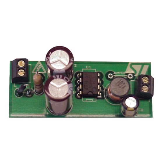
Figure 1.
Table 1.
Output version 1
Output version 2
Output version 3
Output version 4
November 2007
Designing a low cost power supply using a
Evaluation board (STEVAL-ISA035V1)
Operating conditions for the four samples
Board version (with changes)
Input voltage range
Input voltage frequency range
VIPer22ADIP-E
VIPer12ADIP-E
VIPer22ADIP-E
VIPer12ADIP-E
VIPer12/22A-E in a buck configuration
Rev 4
AN2544
Application note
Output voltage and current
85 V
to 264 V
ac
ac
50/60 Hz
12 V at 350 mA
4.2 W
12 V at 200 mA
2.4 W
16 V at 350 mA
5.6 W
16 V at 200 mA
3.2 W
1/17
www.st.com
Advertisement
Table of Contents

Related Manuals for ST VIPer12A-E

Summary of Contents for ST VIPer12A-E
-
Page 1: Figure 1. Evaluation Board (Steval-Isa035V1)
VIPer12/22A-E. Four different examples are covered. The VIPer12A-E is used for 12 V at 200 mA and 16 V at 200 mA. The VIPer22A-E is used for 12 V at 350 mA and 16 V at 350 mA. The same board can be used for any output voltage from 10 V to 35 V. -
Page 2: Table Of Contents
Contents AN2544 Contents Circuit operation ..........4 Input line rectification and line conducted filter . - Page 3 AN2544 List of figures List of figures Figure 1. Evaluation board (STEVAL-ISA035V1) ........1 Figure 2.
-
Page 4: Circuit Operation
Circuit operation AN2544 Circuit operation Input line rectification and line conducted filter The circuit operations for all four versions are basically the same. The difference is in the circuit for startup. Version 1 will be described here with reference to Figure 3. -
Page 5: Inductor Selection
It is set up for 12 V with a maximum current of 350 mA. If less current is required, then the VIPer22A-E can be changed to a VIPer12A-E and C2 can be decreased from 10 µf to 4.7 µF. This delivers up to 200 mA. Figure 4 shows the same board but for 16 V output or higher, D6 and C4 can be left out. -
Page 6: Figure 2. Inductor Current: 470 Μh Vs 1000 Μh
Circuit operation AN2544 Figure 2. Inductor current: 470 µH VS 1000 µH The blue trace is the current with 470 µH inductor and the purple trace is the current with a 1000 µH inductor. On the above scope plot in Figure 2, the trace represents the current going through the inductor. -
Page 7: Figure 3. Schematic For 12 V At 350 Ma
AN2544 Circuit operation Figure 3. Schematic for 12 V at 350 mA 7/17... -
Page 8: Figure 4. Schematic For 16 V At 350 Ma
Circuit operation AN2544 Figure 4. Schematic for 16 V at 350 mA 8/17... -
Page 9: Board Layout
AN2544 Circuit operation Board layout A composite view of the board shows a double-sided board with surface mount components on the bottom. The top is a ground plane which helps with EMI. The actual measurements of the PC board are 55 mm by 23 mm. Figure 5. - Page 10 Zener and Vf pin path. The output voltage can be changed by changing DZ from 16 V Zener to a higher value matching the output voltage. If less current is required, the board can be changed with a VIPer12A-E dip which is pin-for- pin compatible with the VIPer22ADIP-E.
-
Page 11: Burst Mode In No-Load Or Very Light Load
AN2544 Circuit operation The VIPer internal 1 mA current source charges up the V capacitor. When the voltage on the V pin reaches the V startup threshold (Worse case is 13 V) the VIPer starts pulsing, raising the output voltage to the point of bootstrapping. The V capacitor needs to supply the energy to supply the necessary output current and to charge up the output capacitor, before the V... -
Page 12: Short Circuit
Circuit operation AN2544 Figure 10. Burst mode Short circuit The VIPer has pulse-by-pulse current limit. When the current ramps up to the current limit, the pulse is terminated. This is manifested by reducing the output voltage as the current is increased. -
Page 13: Performance
Circuit operation Performance Regulation for the VIPer22A-E and VIPer12A-E can be seen below. Keep in mind that the buck topology will peak charge at zero load. DZ1 will clamp the voltage to 3 - 4 V above the output. Load regulation is taken from 0.03 A to 0.35 A. -
Page 14: Figure 12. Load Regulations For 12 V Output
Circuit operation AN2544 Table 6. VIPer12ADIP-E, 12 V at 200 mA (continued) VIPer12 buck 12 V / 200 mA #1 12 V load 12 V W in Efficiency Ripple mv pp at 120 V Blue Angel at no-load at 115 V in W 0.15 Short circuit... -
Page 15: Emi Conducted
AN2544 Circuit operation Figure 14. Efficiency Efficiency VS Input Line for 12V output effic. @ 100ma effic. @ 200ma effic. @ 350ma Input Line Efficiency is about 75% at 120 V . Efficiency is better at higher output voltages. 1.10 EMI conducted EMI was checked for all four versions for maximum peak reading. -
Page 16: Conclusion
Conclusion AN2544 Figure 17. VIPer22-E, 16 V at 350 mA output Figure 18. VIPer12-E, 16 V at 200 mA output Conclusion Using the VIPer in the buck mode has its benefits for appliances and other industrial equipment which require a reference to neutral. For currents up to 350 mA and voltages greater than 10 V, it is beneficial to use this inexpensive power supply. - Page 17 No license, express or implied, by estoppel or otherwise, to any intellectual property rights is granted under this document. If any part of this document refers to any third party products or services it shall not be deemed a license grant by ST for the use of such third party products or services, or any intellectual property contained therein or considered as a warranty covering the use in any manner whatsoever of such third party products or services or any intellectual property contained therein.
Need help?
Do you have a question about the VIPer12A-E and is the answer not in the manual?
Questions and answers