Advertisement
Quick Links
2562366A
REV. A 1007
Printed in U.S.A.
SAFETY MESSAGE TO INSTALLERS
FEDERAL SIGNAL LIGHT SYSTEMS
People's lives depend on your safe instal-
lation of our products. It is important to
read, understand and follow all instructions
shipped with the products. In addition, listed
below are some other important safety in-
structions and precautions you should follow:
•
To properly install a light assembly: you must
have a good understanding of automotive
electrical procedures and systems, along with
proficiency in the installation and use of safety
warning equipment.
•
When installing equipment or wiring inside air
bag equipped vehicles, the installer MUST en‑
sure that the equipment or wiring is installed
ONLY in areas recommended by the vehicle
manufacturer. Failure to observe this warn‑
ing will reduce the effectiveness of the air bag,
damage the air bag, or potentially damage or
dislodge the equipment, causing serious injury
or death to you or others.
•
When drilling into a vehicle structure, be sure
that both sides of the surface are clear of any‑
thing that could be damaged.
•
A light system is a high current device. In
order for it to function properly, a separate
ground connection must be made. If practical,
it should be connected to the negative battery
terminal. At a minimum, it may be attached
to a solid metal body or chassis part that will
provide an effective ground path as long as the
light system is to be used.
•
Locate light system controls so the VEHICLE
and CONTROLS can be operated safely under
all driving conditions.
•
This product contains high intensity LED de‑
vices. To prevent eye damage, DO NOT stare
into the light beam at close range.
•
You should frequently inspect the light system
to ensure that it is operating properly and that
it is securely attached to the vehicle.
•
File these instructions in a safe place and refer
to them when maintaining and/or reinstalling
the product.
Failure to follow all safety precautions and
instructions may result in property damage, serious
injury, or death to you or others.
INSTALLATION AND MAINTENANCE INSTRUCTIONS
ARJENT® S2 SERIES B LED/HALOGEN LIGHT ASSEMBLY
OF
FOR
I.
UNPACKING.
After unpacking the Arjent S2 lightbar, inspect it for
damage that may have occurred in transit. If the unit has
been damaged, file a claim immediately with the carrier,
stating the extent of damage. Carefully check all envelopes,
shipping labels and tags before removing or destroying
them.
II.
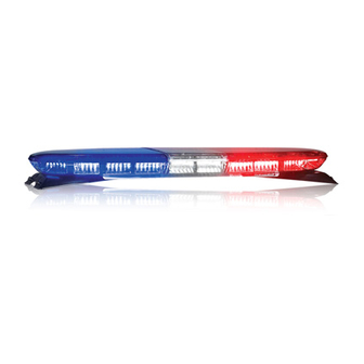
DESCRIPTION.
The Arjent S2 lightbar is available in either a 36", 44"
or 53" length and operates on a nominal input of 13.6 volts
DC (11 volts DC minimum). Clear polycarbonate bases
along with clear or colored polycarbonate domes house a
multi‑channel programmable (via serial interface module)
circuit board assembly within the bar. The multi‑channel
PCB assembly is connected in turn to additional multiple
circuit board panels, each having the availability of 4 to 5
maximum factory‑installed options per panel. The lightbars
have an operating temperature range of ‑30°C to +65°C
(‑22°F to +149°F). They may be mounted with a hook,
permanent, or flat mounting kit to the vehicle. Available
built to order options on the Arjent S2 include:
Panelized Solaris LED Options:
XD1LC6‑A, ‑R, ‑B, ‑W, ‑G: 6‑button Solaris S2 LED
light head
XDALED‑A, ‑R, ‑B, ‑W, ‑G: 3‑button Solaris S2 LED
light head, alley light position (factory default at front
light cutoff)
• Flashing pattern selectability of the LED options
may be specified via programming of the lightbar.
See table 2.
• SignalMaster operation is accomplished via
programming of the lightbar.
4‑pos. SignalMaster available on the 36" bar;
6‑pos. SignalMaster available on the 44" bar;
8‑pos. SignalMaster available on the 53" bar
• Steady‑burn availability of 1 or 2 front LED
heads must be specified via the Arjent S2 initial
order entry.
Panelized Halogen Options (maximum of 6 per
lightbar):
XDAHAL
Alley Light, 35 watts/head (MR 11)
adjustable
XDTD
Takedown Light 50 watts/head
XDWL
Work Light 50 watts/head
• Flashing of the halogen options is accomplished via
programming of the lightbar.
Mounting Options:
XAHKN‑SC, XAHK‑SC
XAPKN‑SC, XAPK‑SC
XAFM
Hook Mount, Neutral or
Black
Permanent Mount, Neutral
or Black
Flat Mount
Advertisement

Related Manuals for Federal Signal Corporation ARJENT S2 SERIES


Summary of Contents for Federal Signal Corporation ARJENT S2 SERIES
- Page 1 2562366A REV. A 1007 Printed in U.S.A. INSTALLATION AND MAINTENANCE INSTRUCTIONS ARJENT® S2 SERIES B LED/HALOGEN LIGHT ASSEMBLY SAFETY MESSAGE TO INSTALLERS UNPACKING. FEDERAL SIGNAL LIGHT SYSTEMS After unpacking the Arjent S2 lightbar, inspect it for damage that may have occurred in transit. If the unit has been damaged, file a claim immediately with the carrier, stating the extent of damage. Carefully check all envelopes, shipping labels and tags before removing or destroying People’s lives depend on your safe instal- them. lation of our products.
-
Page 2: Installation
III. INSTALLATION. IGNITION NOTICE 16AWG Improper warning system and/or two‑way radio system operation may result if a two‑way radio antenna is installed on, or within 18‑inches of, the lightbar. Before permanent installation of the light‑ FUSE bar or a two‑way radio antenna, test the warning 40AMP FSC SERIAL INTERFACE MODULE system and two‑way radio system. DO NOT install PART #8583446 REFERENCE LIGHTBAR INSTRUCTION SHEET 2562248 a two‑way radio antenna on the lightbar. BATTERY Some installations may require relocation of the SERIAL, CAT5., CONTROL CABLE two‑way radio antenna to a trunk or fender loca‑ BLACK 10AWG tion. RED 10AWG Warning system failure may result if additional holes are drilled in the lightbar, or if auxiliary 290A5859 devices are installed on the lightbar. DO NOT drill Figure 1. -
Page 3: Basic Maintenance
F. Cutoff for LED Alley Light Option. The XDALED‑A, ‑R, ‑B, ‑W, ‑G option installed in Crazing (cracking) of domes will cause re- the alley position is factory set for front light cutoff of both duced effectiveness of light system. Do not the passenger and driver sides of the option. The cutoff may use cleaning agents (which will cause craz- be changed to the rear by means of an on‑board 2‑position ing) such as strong detergents, solvents, or jumper found on the component side fo the 2005395 panel. petroleum products. - Page 4 panel from the lightbar. Removal of the dome above the Table 1. panel, followed by removal of the screws restraining the Function Description panel and disconnection of the 9‑wire cable harness (see figure 5) will allow access to the reflector’s cleaning or Takedown, Worklight 50W Halogen, GH‑8 (bi‑pin) replacement. Refer to table 1 for replacement part number. Part No. 8107169 Alley 35W Halogen MR11 Part No. 8107241 NOTE Reflector, 6 LED 6‑Button, S2 (Solaris) Part No. 8653104 Individual LED Modules cannot be serviced. The Reflector, 3 LED Part No. 8583462 entire LED panel is replaced. (Alley Position Option) Multi‑channel Part No. 2005382 2. LED Panel Replacement. circuit board In the rare occurrence a LED module is found C. Cleaning Reflector Assemblies. not functioning properly, the parent circuit board panel to which it belongs needs to be replaced with its equivalent. Use a soft tissue to clean the reflectors. Avoid A corresponding label may be found on the topside of each heavy pressure and the use of caustic or petroleum base of the LED panels with a 2005xxxx‑xxxxxxxx pc board part solvents which will scratch or dull the surface.
-
Page 5: Control Board Replacement
15A FUSES board (#2005382) needs to be replaced, the inboard LED panel on the passenger’s side must be disconnected and removed first to gain access to the main control board. Next, disconnect the power and ground leads to the board. The Serial input cable must then be disconnected along with the associated wire harness leads to the board. Last, the four screws restraining the control board must then be removed for its replacement (see figure 6). Copyright 2007 Federal Signal Corporation 290A55865 Figure 7. Internal vs External SignalMaster Configuration. DISCONNECT ATTACHED 9-CONDUCTOR CABLE FROM PANEL END FOR CONTROL BOARD REMOVAL DISCONNECT ALL ATTACHED: > RS485 CABLE >... - Page 6 Table 2. 44” Arjent S2 Flash Pattern Lighting Standard Compliance Table (for software revision ARJM44B and higher). Pattern Number SAE J845 Compliant Title 13 Compliant Yes Yes Yes Yes Yes Yes Yes Yes 10 Default Mode 1 Yes Yes Yes Yes Yes 17 Default Mode 2 Yes Yes Yes 22 Intersection 23 26 Default Mode 3 Yes 27 For testing only...
Need help?
Do you have a question about the ARJENT S2 SERIES and is the answer not in the manual?
Questions and answers