
Related Manuals for Zimmer Biomet Avenue T


Summary of Contents for Zimmer Biomet Avenue T
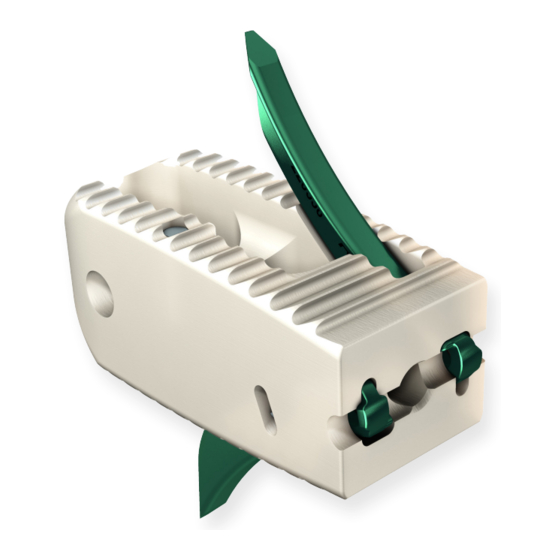
- Page 1 Thoracolumbar Solutions Avenue ® TLIF Cage with erteBRIDGE ® P L A T I N G T E C H N O L O G Y Surgical Technique Guide...
- Page 2 Avenue T TLIF Cage—Surgical Technique ® VerteBRIDGE® Plating is the integrated fixation designed specifically for the Avenue T cage.
-
Page 3: Table Of Contents
Supplemental Fixation Implant Removal for Revision Implant Kit and Instrument Set Device Description and Use Guidelines Zimmer Biomet Spine does not practice medicine. This technique was developed in conjunction with health care professionals. This document is intended for surgeons and is not intended for laypersons. Each... -
Page 4: Patient Positioning
Avenue T TLIF Cage—Surgical Technique Guide ® PATIENT POSITIONING Figure 1 OR layout STEP 1 Place the patient in the prone or knee-chest position on a radiolucent operating table. Adjust the table (as needed) so that the C-Arm provides true A/P images when at 90° and true lateral images at 0°. -
Page 5: Facetectomy And Disc Space Preparation
Avenue T TLIF Cage—Surgical Technique Guide ® FACETECTOMY AND DISC SPACE PREPARATION Figure 2 Facet resection for a TLIF approach STEP 2 Depending on the pathology, it may be necessary to partially or fully resect the facet joint and/or the lamina. A facetectomy and/or laminotomy is performed using the surgeon's preferred technique and instruments. -
Page 6: Distraction
Avenue T TLIF Cage—Surgical Technique Guide ® DISTRACTION Figure 3 Distraction STEP 3 Note: Proper distraction is required to achieve and Gradually distract the disc space using the paddle maintain desired disc height. Complete a thorough distractors, available in 1mm increments. The final disc discectomy to ensure that the proper implant size is height achieved should be consistent with the disc chosen. -
Page 7: Discectomy And Endplate Preparation
Avenue T TLIF Cage—Surgical Technique Guide ® DISCECTOMY AND ENDPLATE PREPARATION Figure 4a Shaver Figure 4b Figure 4c Straight curette Angled curette STEP 4 Caution: Do not use shavers for distraction of the Use the shavers to continue the discectomy and prepare interbody space. -
Page 8: Implant Size Selection
Avenue T TLIF Cage—Surgical Technique Guide ® IMPLANT SIZE SELECTION Figure 5a 5° H12mm paddle distractor 30mm 34mm Figure 5b This side points 5° trial to the left side of collar 2 to 5mm Figure 5c Figure 5d Figure 5e Axial View A/P View Lateral View... -
Page 9: Cage Preparation
Avenue T TLIF Cage—Surgical Technique Guide ® CAGE PREPARATION KNOB Figure 6 Graft fusion chamber STEP 6 The graft fusion chamber must be filled with allograft or autograft. Place the cage in the graft support and lock the cage by turning the graft support knob. Compact the draft in the bone graft chamber of the cage using the graft compactor (Figure 6). -
Page 10: Implant To Cage Holder Assembly
Avenue T TLIF Cage—Surgical Technique Guide ® IMPLANT TO CAGE HOLDER ASSEMBLY KNOB GROOVE CAGE HOLDER BODY THREADED ROD RETAINING WING Figure 7 Cage holder assembly STEP 7 Caution: The connection between the cage and the Slide the inner threaded rod inside the cage holder body. - Page 11 Avenue T TLIF Cage—Surgical Technique Guide ® MARKING SLOT LOCKED HOLDERS PLATE Figure 8a HOLDER Cage holder assembly IMPACTOR IMPACTOR Figure 8 FLEXIBLE Toeing pad position BLADE Figure 8b LOCKED Cage holder assembly IMPACTORS STEP 8 Select the plate length (S or M) and insert the plate holders on each side of the cage holder (Figure 8a).
-
Page 12: Cage Insertion
Avenue T TLIF Cage—Surgical Technique Guide ® CAGE INSERTION ANTERIOR MARKER A/P VIEW CENTRAL MARKERS ANTERIOR MARKER LATERAL VIEW Figure 9 Proper implant placement STEP 9 Note: Anterior marker is 1mm from the anterior cage Prior to cage insertion, bone graft material may be placed anteriorly or contralaterally. -
Page 13: Plate Insertion
Avenue T TLIF Cage—Surgical Technique Guide ® PLATE INSERTION DOUBLE IMPACTOR CONTACT FLEXIBLE BLADE LOCKED IMPACTORS UNLOCKED IMPACTORS Figure 10 Plate Insertion STEP 10 Once the final cage position is achieved, the plates can be inserted. The impaction of the plates is performed simultaneously. - Page 14 Avenue T TLIF Cage—Surgical Technique Guide ® PLATE INSERTION (continued) MECHANICAL STOP Figure 11a Plate Insertion STEP 11 Manually push the double impactor to advance the impactors and bring the tips of the plates in contact with the vertebral endplates. Caution: Check the alignment of the cage holder with the cage before starting impaction of the plates.
-
Page 15: Cage Holder Removal And Final Verification
Avenue T TLIF Cage—Surgical Technique Guide ® CAGE HOLDER REMOVAL AND FINAL VERIFICATION Figure 12b A/P View Figure 12a Cage holder removal STEP 12 Remove the double impactor. Unscrew the knob to disengage the cage from the cage holder (Figure 12a). Remove the cage holder. -
Page 16: Supplemental Fixation
T TLIF Cage—Surgical Technique Guide ® SUPPLEMENTAL FIXATION The Avenue T TLIF Cage system is designed for use with or without integrated fixation and must be used in conjunction with supplemental fixation cleared by FDA for use in the lumbar spine. -
Page 17: Implant Removal For Revision
Avenue T TLIF Cage—Surgical Technique Guide ® IMPLANT REMOVAL FOR REVISION SLOTTED MALLET UNLOCKING THREADED SHAFT REMOVAL TUBE REMOVAL SCREWDRIVER REMOVAL HANDLE REVISION THREADED SHAFT REMOVAL HOOK REMOVAL HOOK GUIDE Figure 13 Implant removal tools STEP 13 If needed, the unlocking threaded shaft facilitates removal of the plates from the cage. - Page 18 Avenue T TLIF Cage—Surgical Technique Guide ® IMPLANT REMOVAL FOR REVISION (continued) Figure 14a Implant removal tube STEP 14 Screw the removal tube onto the unlocking threaded shaft (Figure 14a). Insert the removal screwdriver inside the tube. To unlock the plates, screw the removal assembly into the threaded hole on the posterior side until it stops turning (Figure 14b).
- Page 19 Avenue T TLIF Cage—Surgical Technique Guide ® REVISION HOLE Figure 15a Figure 16a Find removal hole Guide approach REMOVAL HOOK Figure 15b Figure 16b Insert removal hook Final position of the guide STEP 15 STEP 16 Remove the removal screwdriver and leave the Position the removal hook guide on the tube and threaded shaft and removal tube.
- Page 20 Avenue T TLIF Cage—Surgical Technique Guide ® IMPLANT REMOVAL FOR REVISION (continued) REMOVAL HOOK OR FORCEPS PLATE PARTLY INSERTED INTO Figure 17b BONE Scew removal handle Figure 17a Figure 17c Position slotted mallet for removal Remove cage STEP 17 Screw the removal handle on the removal tube Place the slot of the slotted mallet across the removal (Figure 17b).
- Page 21 Avenue T TLIF Cage—Surgical Technique Guide ® IMPLANTS AND INSTRUMENTS Avenue T Implants, Kit Number: ATKIT Avenue T Instruments, Kit Numbers: ATSET1 and ATSET2 DESCRIPTION DESCRIPTION SIZE PART NUMBER SIZE PART NUMBER Anchoring Plate AT0007T T-Handle G103521 AT0008T Avenue T Cage H8mm L30mm 0°...
- Page 22 In addition, so as to favor bone growth, the Avenue T TLIF Cage must be filled with Warnings bone graft.
- Page 23 (e.g., pedicle screws). approach, orthopedic surgery, and the use of general • The Avenue T TLIF Cage system has not been evaluated for anesthesia should be explained to the patient prior safety and compatibility in the MR environment. to surgery.
- Page 24 ©2017 Zimmer Biomet Spine, Inc. All rights reserved. All content herein is protected by copyright, trademarks and other intellectual property rights owned by or licensed to Zimmer Biomet Spine, Inc. or one of its affiliates unless otherwise indicated, and must not be redistributed, duplicated or disclosed, in whole or in part, without the express written consent of Zimmer Biomet Spine.
Need help?
Do you have a question about the Avenue T and is the answer not in the manual?
Questions and answers