Huawei RRU3804 User Manual
Hide thumbs
Also See for RRU3804:
- User manual (46 pages) ,
- Hardware maintenance manual (58 pages) ,
- User manual (100 pages)

Related Manuals for Huawei RRU3804


Summary of Contents for Huawei RRU3804
- Page 1 RRU3804 V100 User Guide Issue Date 2007-11-29 Part Number 31018637 Huawei Technologies Proprietary...
-
Page 2: Index
Huawei Technologies Co., Ltd. provides customers with comprehensive technical support and service. For any assistance, please contact our local office or company headquarters. Huawei Technologies Co., Ltd. Address: Huawei Industrial Base Bantian, Longgang Shenzhen 518129 People's Republic of China Website: http://www.huawei.com... -
Page 3: Table Of Contents
2.2.5 Engineering Specifications of the SRXU.....................2-15 2.3 RRU3804 Cables............................2-15 2.3.1 PGND Cable of the RRU3804......................2-16 2.3.2 Power Cable of the RRU3804......................2-17 2.3.3 AISG Multi-Wire Cable of the RRU3804/SRXU................2-18 2.3.4 AISG Extension Cable of the RRU3804/SRXU..................2-19 2.3.5 BBU3806-RRU/SRXU CPRI Optical Cable..................2-20 2.3.6 BBU3806C-RRU/SRXU CPRI Optical Cable..................2-21 2.3.7 RF Jumper of the RRU3804/SRXU.....................2-23... - Page 4 3.7.7 Installing the AISG Extension Cable of the RRU3804/SRXU............3-94 3.7.8 Installing the Boolean/RS485 Input Cable of the RRU3804...............3-94 3.7.9 Opening and Closing the Cover Plate of the RRU3804 Cabling Cavity..........3-96 3.7.10 Opening and Closing the Cover Plate of the SRXU Cabling Cavity..........3-99 3.8 Checking RRU3804 and SRXU Hardware Installation................3-101...
- Page 5 RRU3804 User Guide Contents 3.8.3 Checklist for Field Cleanliness of RRU3804 and SRXU Installation..........3-105 3.9 Installing the Housing of the RRU3804 and SRXU...................3-105 4 Maintaining RRU3804 and SRXU Hardware................4-1 4.1 Equipment Maintenance Items for the DBS3800...................4-2 4.2 Powering On/Off the RRU3804/SRXU......................4-2 4.2.1 Powering on the RRU3804/SRXU......................4-2...
- Page 7 Figure 1-3 Slant angle............................1-11 Figure 1-4 One meter higher than the eave......................1-11 Figure 2-1 Function modules of the DBS3800....................2-2 Figure 2-2 RRU3804............................2-5 Figure 2-3 Panels of the RRU3804........................2-9 Figure 2-4 SRXU..............................2-12 Figure 2-5 Panels of the SRXU..........................2-14 Figure 2-6 PGND cable............................2-16 Figure 2-7 2-hole terminal..........................2-16...
- Page 8 Figure 3-6 Installation modes of three RRU3804s with three SRXUs..............3-6 Figure 3-7 Recommended space requirements of one RRU3804 with and without the SRXU (unit: mm)..3-7 Figure 3-8 Minimal space requirements of one RRU3804 with and without the SRXU (unit: mm)....3-8 Figure 3-9 Space requirements of two combined RRU3804s (unit: mm) ............3-8...
- Page 9 Figure 3-72 Installing a pole fixture........................3-59 Figure 3-73 Assembling the module and mounting plate..................3-60 Figure 3-74 Securing the module and mounting plate..................3-61 Figure 3-75 Assembled RRU3804 tied with the rope..................3-61 Figure 3-76 Mounting the upper fixture assembly.....................3-62 Figure 3-77 Measuring L1 and L2........................3-63 Figure 3-78 Installing the assembled RRU3804....................3-64...
- Page 10 Figure 3-86 SRXUs installed on the two RRU3804s..................3-70 Figure 3-87 Removing the plastic housings.......................3-70 Figure 3-88 Securing the connecting boards on the RRU3804 module in ordinary mode........3-71 Figure 3-89 Securing the attachment plate on the first SRXU................3-71 Figure 3-90 Installing the first SRXU........................3-72 Figure 3-91 Securing the first SRXU.........................3-73...
- Page 11 Table 2-5 Specifications for the alarm port on the RRU3804................2-8 Table 2-6 Other ports on the RRU3804........................2-8 Table 2-7 Ports and LEDs on the panels of the RRU3804.................2-10 Table 2-8 Power input to the RRU3804......................2-11 Table 2-9 LEDs on the SRXU..........................2-12 Table 2-10 Power supply ports on the SRXU....................2-13...
- Page 12 RRU3804 Tables User Guide Table 4-3 LEDs on the SRXU..........................4-3 Huawei Technologies Proprietary Issue 01 (2007-11-29)
-
Page 13: About This Document
This document is intended for: NodeB installers System engineers Site maintainers Change History For changes in the document, refer to Changes in RRU3804 User Guide. Organization 1 Safety Information 2 RRU3804 and SRXU Hardware This describes the RRU3804 equipment, SRXU equipment, and related cables. - Page 14 RRU3804 About This Document User Guide After the RRU3804 and SRXU are deployed, accepted, and put into use, routine maintenance is performed to ensure the functionality of the modules. Conventions 1. Symbol Conventions The following symbols may be found in this document. They are defined as follows...
- Page 15 Select and release the primary mouse button without moving the pointer. Double-click Press the primary mouse button twice continuously and quickly without moving the pointer. Drag Press and hold the primary mouse button and move the pointer to a certain position. Issue 01 (2007-11-29) Huawei Technologies Proprietary...
-
Page 17: Safety Information
Safety Information 1.1 Safety Precautions This section describes certain safety precautions. Read and follow these safety precautions before installing, operating, and maintaining Huawei devices.This manual can also help to choose the measurement device and testing device. Following All Safety Precautions Before any operation, read the instructions and precautions in this document carefully to minimize the possibility of accidents. - Page 18 Any replacement of the device or part of the device (including the software) or any change made to the device must be performed by qualified or authorized personnel of Huawei. Any fault or error that might cause safety problems must be reported immediately to the personnel in charge.
-
Page 19: Electricity Safety
The following requirements are suitable only for the wireless base station or the device with an antenna or GPS antenna. DANGER In a thunderstorm, do not perform operations on high voltage and AC power supply facilities or on a steel tower and mast. Issue 01 (2007-11-29) Huawei Technologies Proprietary... - Page 20 (LIC). In the following situations, the human body generates a static electromagnetic field: Movement of body parts Clothes friction Friction between shoes and the ground Huawei Technologies Proprietary Issue 01 (2007-11-29)
-
Page 21: Inflammable Environment
Do not place the device in the environment that has inflammable and explosive air or fog. Do not perform any operation in this environment. Any operation of the electrical device in the inflammable environment causes danger. Issue 01 (2007-11-29) Huawei Technologies Proprietary... -
Page 22: Battery
Keep metal objects away from the battery to prevent short circuit. If they have to be used, disconnect the battery in use before performing any other operation. Huawei Technologies Proprietary Issue 01 (2007-11-29) - Page 23 Antacids must be used according to the instructions provided by the battery manufacturer. Lithium Battery CAUTION There is danger of explosion if the battery is incorrectly replaced. Replace the lithium battery with the same or equivalent type recommended by the manufacturer. Issue 01 (2007-11-29) Huawei Technologies Proprietary...
-
Page 24: Radiation
Read the following guidelines to prevent laser radiation: Huawei Technologies Proprietary Issue 01 (2007-11-29) -
Page 25: Working At Heights
Do not access the areas under the arm of the crane and the goods in suspension when lifting weights. Ensure that the operators have been trained and qualified. Check the weight lifting tools and ensure that they are intact. Issue 01 (2007-11-29) Huawei Technologies Proprietary... -
Page 26: Figure 1-2 Lifting A Weight
Do not climb higher than the fourth highest step of the ladder. If you tend to climb to the roof, the length of the ladder should be at least one meter higher than the eave, as shown inFigure 1-4. 1-10 Huawei Technologies Proprietary Issue 01 (2007-11-29) -
Page 27: Mechanical Safety
Metal shavings from the drilling may result in a short-circuit of the circuit board if they get into the cabinet. Before drilling a hole on the cabinet, remove the cables from the cabinet. Issue 01 (2007-11-29) Huawei Technologies Proprietary 1-11... - Page 28 When moving or lifting a chassis, hold the handle or bottom of the chassis. Do not hold the handle of the installed modules in the chassis, such as the power module, fan module, or board. 1-12 Huawei Technologies Proprietary Issue 01 (2007-11-29)
-
Page 29: Others
C, move the cables into a place at a room temperature and store the cables for more than 24 hours before installation. Move the cables with care, especially at a low temperature. Do not drop the cables directly from the vehicle. Issue 01 (2007-11-29) Huawei Technologies Proprietary 1-13... -
Page 31: Rru3804 And Srxu Hardware
About This Chapter This describes the RRU3804 equipment, SRXU equipment, and related cables. 2.1 RRU3804 Equipment The RRU3804 is an outdoor remote radio unit. The RRU3804 that is connected to the SRXU supports 4-way RX diversity. 2.2 SRXU Equipment The SRXU is an extended RF interface module that provides two RX channels for RF signals. -
Page 32: Rru3804 Equipment
This describes the function modules and auxiliary facilities in the DBS3800 product family. 2.1.2 Appearance of the RRU3804 The RRU3804 features a modular structure with its ports at the module bottom and on the cabling cavity. 2.1.3 LEDs on the RRU3804 The LEDs, on the LED panel of the RRU3804, indicate the running status of the RRU3804. - Page 33 Outdoor remote radio unit. It receives and transmits RF signals and then transmits the processed signals to the BBU3806 or BBU3806C. RRU3804 Outdoor remote radio unit. The RRU3804 that is connected to the SRXU supports 4-way RX diversity. The BBU3806, BBU3806C, and RRU3801C can be combined into a BTS3803 or BTS3803C.
- Page 34 RRU3804 2 RRU3804 and SRXU Hardware User Guide Auxiliary Description Facility Auxiliary facility box for outdoor application. The AFB provides the following functions: Four AC power outputs and four DC power outputs AC surge protection Temperature control Alarm reporting 5 U space for your devices For details on the functions of the AFB, refer to the AFB User Guide.
-
Page 35: Appearance Of The Rru3804
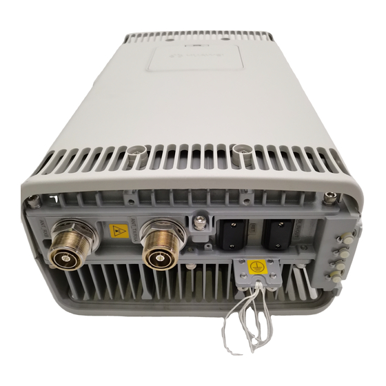
RRU3804. On the left is a front view of the RRU3804 without the housing, in the middle is a side view of the RRU3804 without the housing, and on the right is a front view of the RRU3804 housing. -
Page 36: Leds On The Rru3804
2 RRU3804 and SRXU Hardware User Guide 2.1.3 LEDs on the RRU3804 The LEDs, on the LED panel of the RRU3804, indicate the running status of the RRU3804. For the positions of the LEDs on the RRU3804, refer to 2.1.5 Panels of the RRU3804. -
Page 37: Ports On The Rru3804
The optical module is not in position or is powered off. 2.1.4 Ports on the RRU3804 The ports on the RRU3804 consist of grounding ports, power supply ports, transmission ports, alarm ports, and other ports. Grounding Ports The RRU3804 has four grounding bolts at the bottom. -
Page 38: Panels Of The Rru3804
DIN, round, and waterproof Interconnection between combined cabinets 2.1.5 Panels of the RRU3804 The RRU3804 has a bottom panel, a cabling cavity panel, and an LED panel. Figure 2-3 shows the panels of the RRU3804. Huawei Technologies Proprietary Issue 01 (2007-11-29) -
Page 39: Figure 2-3 Panels Of The Rru3804
RRU3804 User Guide 2 RRU3804 and SRXU Hardware Figure 2-3 Panels of the RRU3804 Table 2-7 describes the ports and LEDs on the panels of the RRU3804. Issue 01 (2007-11-29) Huawei Technologies Proprietary... -
Page 40: Engineering Specifications Of The Rru3804
2.1.6 Engineering Specifications of the RRU3804 This describes the engineering specifications for the RRU3804. Dimensions The dimensions of the RRU3804 (including the mounting plate and housing) are 280 mm x 155 mm x 488 mm (W x D x H). Weight The weight of the RRU3804 is 17 kg at most. -
Page 41: Srxu Equipment
The SRXU receives RF signals from the antenna system, down-converts the signals to IF signals, and then transmits them to the RRU3804 after amplification, analog-to-digital conversion, digital down-conversion, matched filtering, and DAGC. The RRU3804 forwards the signals to the BBU or the macro NodeB. -
Page 42: Leds On The Srxu
RRU3804 2 RRU3804 and SRXU Hardware User Guide Figure 2-4 SRXU 2.2.2 LEDs on the SRXU The LEDs, on the LED panel of the SRXU, indicate the running status of the SRXU. For the positions of the LEDs on the SRXU, refer to 2.2.4 Panels of the... -
Page 43: Ports On The Srxu
RRU3804 User Guide 2 RRU3804 and SRXU Hardware Label Color Status Description 0.5s ON, 0.5s OFF The CPRI link is out of lock. (red) The optical module is not in position or is powered off. 2.2.3 Ports on the SRXU The ports on the SRXU consist of grounding ports, power supply ports, transmission ports, and other ports. -
Page 44: Panels Of The Srxu
RRU3804 2 RRU3804 and SRXU Hardware User Guide Application Port Quanti Connector Type Interconnection between combined cabinets 2.2.4 Panels of the SRXU The SRXU has a bottom panel, a cabling cavity panel, and an LED panel. Figure 2-5 shows the panels of the SRXU. -
Page 45: Engineering Specifications Of The Srxu
2.3.1 PGND Cable of the RRU3804 The PGND cable ensures the grounding of the RRU3804. 2.3.2 Power Cable of the RRU3804 The RRU3804 uses a shielded –48 V DC power cable. The cable feeds external –48 V DC power to the RRU3804. Issue 01 (2007-11-29) -
Page 46: Pgnd Cable Of The Rru3804
2.3.4 AISG Extension Cable of the RRU3804/SRXU When the distance between the RCU and the RRU3804/SRXU is longer than 5 m, the AISG multi-wire cable is not long enough to cover the distance and the AISG extension cable is used. -
Page 47: Power Cable Of The Rru3804
User Guide 2 RRU3804 and SRXU Hardware Installation Position One end of the PGND cable is connected to the grounding bolt on the RRU3804, and the other end is connected to the nearest grounding bar. 2.3.2 Power Cable of the RRU3804 The RRU3804 uses a shielded –48 V DC power cable. -
Page 48: Aisg Multi-Wire Cable Of The Rru3804/Srxu
2.3.3 AISG Multi-Wire Cable of the RRU3804/SRXU The five-meter-long AISG multi-wire cable connects the RRU3804/SRXU to the Remote Control Unit (RCU). If both RRU3804 and SRXU are installed, the AISG multi-wire cable only connects the SRXU and the RCU. This cable is optional. -
Page 49: Aisg Extension Cable Of The Rru3804/Srxu
2 RRU3804 and SRXU Hardware If both the RRU3804 and the SRXU are installed, the waterproof DB9 connector is linked to the RET port at the bottom of the SRXU, and the standard AISG female connector is linked to the corresponding connector on the RCU or to the AISG extension cable. -
Page 50: Bbu3806-Rru/Srxu Cpri Optical Cable
2.3.5 BBU3806-RRU/SRXU CPRI Optical Cable The CPRI optical cable transmits CPRI signals between BBU3806 and RRU3801C, between BBU3806 and RRU3804, and between RRU3804 and SRXU. Appearance The CPRI optical cable is a multi-mode 2-wire cable with DLC connectors at both ends. -
Page 51: Bbu3806C-Rru/Srxu Cpri Optical Cable
2.3.6 BBU3806C-RRU/SRXU CPRI Optical Cable The CPRI optical cable transmits CPRI signals between BBU3806C and RRU3801C, between BBU3806C and RRU3804, and between RRU3804 and SRXU. Appearance The CPRI optical cable is a multi-mode 2-wire cable with LC connectors at both ends. -
Page 52: Figure 2-14 Cpri Optical Cable
RRU3804 2 RRU3804 and SRXU Hardware User Guide Figure 2-14 CPRI optical cable Pin Assignment Table 2-19 describes the pin assignment for the fiber tails of the CRPI optical cable. These connections are recommended. Table 2-19 Pin assignment for the fiber tails of the CRPI optical cable Label Connect to... -
Page 53: Rf Jumper Of The Rru3804/Srxu
The interconnect jumper transmits RF signals between two RRU3804s/SRXUs. 2.3.7.3 RF Cable Connections of the RRU3804 One end of the RF jumper is connected to the RF ports on the RRU3804 and the other end to the feeder. Which RF port to use depends on the networking modes. -
Page 54: Table 2-20 Rf Jumper Connections Of The Rru3804
RX_IN/OUT on two RRU3804s/SRXUs respectively. RF Cable Connections of the RRU3804 One end of the RF jumper is connected to the RF ports on the RRU3804 and the other end to the feeder. Which RF port to use depends on the networking modes. -
Page 55: Boolean/Rs485 Input Cable Of The Rru3804
SRXU. 2.3.8 Boolean/RS485 Input Cable of the RRU3804 The cable transmits the 2-channel Boolean alarm signals and 1-channel RS485 signals from external devices to the RRU3804. Thus, the external signals are monitored. Issue 01 (2007-11-29) Huawei Technologies Proprietary 2-25... -
Page 56: Figure 2-19 Boolean/Rs485 Input Cable
Installation Position The DB15 male connector is linked to the RS485/EXT_ALM port on the cabling cavity of the RRU3804, and the other end of the cable is connected to the ports for Boolean alarm signals on the external device. 2-26... -
Page 57: Srxu Cables
The PGND cable ensures the grounding of the SRXU. 2.4.2 Power Cable of the SRXU The SRXU uses a shielded DC power cable. The cable feeds power from the RRU3804 to the SRXU. 2.4.3 AISG Multi-Wire Cable of the RRU3804/SRXU The five-meter-long AISG multi-wire cable connects the RRU3804/SRXU to the Remote Control Unit (RCU). -
Page 58: Power Cable Of The Srxu
One end of the PGND cable is connected to the grounding bolt on the SRXU, and the other end is connected to the grounding bolt on the RRU3804. 2.4.2 Power Cable of the SRXU The SRXU uses a shielded DC power cable. The cable feeds power from the RRU3804 to the SRXU. Appearance... -
Page 59: Aisg Extension Cable Of The Rru3804/Srxu
RCU or to the AISG extension cable. If both the RRU3804 and the SRXU are installed, the waterproof DB9 connector is linked to the RET port at the bottom of the SRXU, and the standard AISG female connector is linked to the corresponding connector on the RCU or to the AISG extension cable. -
Page 60: Bbu3806-Rru/Srxu Cpri Optical Cable
AISG female connector of the AISG multi-wire cable. 2.4.5 BBU3806-RRU/SRXU CPRI Optical Cable The CPRI optical cable transmits CPRI signals between BBU3806 and RRU3801C, between BBU3806 and RRU3804, and between RRU3804 and SRXU. 2-30 Huawei Technologies Proprietary... -
Page 61: Figure 2-25 Cpri Optical Cable
RRU3804 User Guide 2 RRU3804 and SRXU Hardware Appearance The CPRI optical cable is a multi-mode 2-wire cable with DLC connectors at both ends. Figure 2-25 shows the CPRI optical cable. Figure 2-25 CPRI optical cable Pin Assignment Table 2-25 describes the pin assignment for the fiber tails. -
Page 62: Rf Jumper Of The Rru3804/Srxu
The RX port on the BBU3806 is connected to the TX port on the RRU. 2.4.6 RF Jumper of the RRU3804/SRXU The RF jumper of the RRU3804/SRXU is of two types: antenna jumper and interconnect jumper. The interconnect jumper is optional, depending on the site configuration. -
Page 63: Figure 2-29 Interconnect Jumper
The antenna jumper with indefinite length is selected according to the distance between the antenna and the RRU3804/SRXU. Connectors are made on site. When the distance between the antenna and the RRU3804/SRXU is shorter than 14 m, the RRU3804/SRXU is directly connected to the antenna through the antenna jumper. -
Page 65: Installing Rru3804 And Srxu Hardware
When the RRU3804 needs to be installed on the ground or rooftop, it supports one-module, two- module centralized, and three-module centralized installation modes. 3.5 Installing the RRU3804 on the Tower Before installing the RRU3804 on the tower, you need to assemble the parts and then lift them up to the tower. 3.6 Installing the SRXU This describes how to install the SRXU on the RRU3804 in one-module, two-module centralized, or three-module centralized installation mode. - Page 66 RRU3804 3 Installing RRU3804 and SRXU Hardware User Guide 3.9 Installing the Housing of the RRU3804 and SRXU After the SRXU is fixed to the RRU3804, install the housing after checking the hardware installation. Huawei Technologies Proprietary Issue 01 (2007-11-29)
-
Page 67: Information About The Installation
It can be mounted on a metal pole or wall. The SRXU can be fixed to the RRU3804 as required. The quantity of the SRXUs is the same as that of the RRU3804s. 3.1.2 Space Requirements of the RRU3804 and SRXU In different installation modes, the RRU3804 and SRXU have the minimal space requirements for cabling and OM. -
Page 68: Figure 3-2 Installation Modes Of One Rru3804 With One Srxu
RRU3804 3 Installing RRU3804 and SRXU Hardware User Guide Figure 3-2 Installation modes of one RRU3804 with one SRXU Installation Modes of Two RRU3804s Figure 3-3 shows the installation modes of two RRU3804s. Figure 3-3 Installation modes of two RRU3804s... -
Page 69: Figure 3-4 Installation Modes Of Two Rru3804S With Two Srxus
RRU3804 User Guide 3 Installing RRU3804 and SRXU Hardware Figure 3-4 Installation modes of two RRU3804s with two SRXUs Installation Modes of Three RRU3804s Figure 3-5 shows the installation modes of three RRU3804s. Figure 3-5 Installation modes of three RRU3804s... -
Page 70: Space Requirements Of The Rru3804 And Srxu
The following figures related to the space requirements assume that the cabling cavities are on the left side of the RRU3804 and SRXU. If the RRU3804 and SRXU are installed with the cabling cavities on the right, the horizontal space requirements are opposite to what are shown in the figures. -
Page 71: Figure 3-7 Recommended Space Requirements Of One Rru3804 With And Without The Srxu (Unit: Mm)
At least 600 mm on the left of the equipment for maintenance. At least 300 mm on the right of the equipment for maintenance. Regardless of whether the SRXU is fixed to the RRU3804, the space requirements are the same. -
Page 72: Figure 3-8 Minimal Space Requirements Of One Rru3804 With And Without The Srxu (Unit: Mm)
3 Installing RRU3804 and SRXU Hardware User Guide Figure 3-8 Minimal space requirements of one RRU3804 with and without the SRXU (unit: The minimal space around the equipment is as follows: 300 mm under the equipment for cabling. It is recommended that the space is 1,200 mm between the bottom and the ground for easy maintenance. -
Page 73: Figure 3-10 Recommended Space Requirements Of Multiple Rru3804S With And Without The Srxus (Unit: Mm)
RRU3804 User Guide 3 Installing RRU3804 and SRXU Hardware The space between the two RRU3804s is as follows: When two RRU3804s are installed horizontally, the space is 1,200 mm at most. When two RRU3804s are installed vertically, the space is 800 mm at most. -
Page 74: Procedure For Installing The Rru3804 And Srxu
300 mm on the right of the equipment for maintenance. 3.2 Procedure for Installing the RRU3804 and SRXU The procedure for installing the RRU3804 and SRXU varies with the installation scenarios. The procedure involves making preparations, installing the RRU3804 and SRXU, connecting related cables, checking the hardware installation, and installing the housing of the RRU3804 and SRXU. -
Page 75: Preparing For Dbs3800 Installation
You choose to prepare the devices, cables, and connectors by yourself. You need to shorten the cable of a specified length. Procedure Step 1 Unpack the RRU3804 and SRXU, check the items in the package, and have tools and instruments ready. For details, refer to 3.3 Preparing for DBS3800 Installation. -
Page 76: Unpacking The Dbs3800
Go to Step The packing case is damaged or soaked, Find the cause and contact Huawei local office. Step 3 Open the packing case. Check the shipped components according to the Packing List, and then perform the next step according to the check result. -
Page 77: Tools And Instruments For Dbs3800 Installation
RRU3804 User Guide 3 Installing RRU3804 and SRXU Hardware CAUTION To protect the equipment and to find out the cause in the case of goods damage, store the equipment and the unpacked cases and materials inside the equipment room. Take photos of the storage environment, rusted or corroded devices, and packing cases and materials, and then file the photos. -
Page 78: Installing The Rru3804 On The Ground Or Rooftop
The instruments must be checked and certified. 3.4 Installing the RRU3804 on the Ground or Rooftop When the RRU3804 needs to be installed on the ground or rooftop, it supports one-module, two- module centralized, and three-module centralized installation modes. 3.4.1 Installing a Single RRU3804 This describes how to install a single RRU3804 module and its mounting plate. -
Page 79: Figure 3-12 Mounting The Upper Fixture Assembly
RRU3804 User Guide 3 Installing RRU3804 and SRXU Hardware Prerequisite The metal pole is ready and the pole diameter stays within the range of 60 mm to 114 mm. Procedure Step 1 Determine the position of the mounting plate by referring to the engineering design and 3.1.2... -
Page 80: Figure 3-13 Measuring L1 And L2
RRU3804 3 Installing RRU3804 and SRXU Hardware User Guide Figure 3-13 Measuring L1 and L2 Condition Action The pole fixtures are neither horizontal nor Go to Step 2 to adjust the fixture assembly. parallel. The pole fixtures are horizontal and parallel. Go to... -
Page 81: Figure 3-15 Securing The Multi-Purpose Attachment Plate On The Mounting Plate
RRU3804 User Guide 3 Installing RRU3804 and SRXU Hardware Figure 3-15 Securing the multi-purpose attachment plate on the mounting plate Step 6 Install the third pole fixture on the mounting plate at the lower part of its back by fastening two... - Page 82 RRU3804 3 Installing RRU3804 and SRXU Hardware User Guide Figure 3-17 Installing the mounting plate Step 8 Mount the fourth pole fixture to the metal pole by fastening two bolts M10 x 110 between the third and the fourth pole fixtures, as shown in Figure 3-18.
-
Page 83: Figure 3-18 Mounting The Lower Fixture Assembly
3 Installing RRU3804 and SRXU Hardware Figure 3-18 Mounting the lower fixture assembly ----End Installing the Mounting Plate of the Single RRU3804 on the Wall This describes how to install the mounting plate on the wall. Procedure Step 1 Determine the position of the mounting plate. -
Page 84: Figure 3-19 Determining The Anchor Points
RRU3804 3 Installing RRU3804 and SRXU Hardware User Guide Figure 3-19 Determining the anchor points Step 2 Drill holes on the anchor points and install the expansion bolt assembly, as shown in Figure 3-20. Figure 3-20 Drilling holes and installing the expansion bolt assembly Use the percussion drill with a Φ14 bit to drill four holes at the anchor points. -
Page 85: Figure 3-21 Securing The Mounting Plate
Use the wrench to fix the mounting plate to the wall by tightening the bolts clockwise. ----End Installing the Single RRU3804 Module This describes how to install the RRU3804 module on a metal pole. The procedures for installing the module in pole or wall installation mode are the same. Prerequisite The RRU3804 mounting plate is installed. -
Page 86: Figure 3-22 One Rru3804 In Ordinary Mode And The Other In Reverse Mode
RRU3804 3 Installing RRU3804 and SRXU Hardware User Guide If the RRU3804 needs to be installed on a metal pole, the PGND cable of the metal pole is connected. Context The RRU3804 module can be installed in either ordinary mode or reverse mode. In reverse mode, the front side of the RRU3804 is fixed to the mounting plate. -
Page 87: Figure 3-23 Securing The Attachment Plate
CAUTION When installing the attachment plate, protect the plastic housing from being scratched. If you find that the plastic housing is put face down when unpacking the RRU3804, install the attachment plate before taking out the RRU3804. If you find that the plastic housing is put face up, lay cardboards or packing bags on the ground. -
Page 88: Figure 3-24 Installing The Module
RRU3804 3 Installing RRU3804 and SRXU Hardware User Guide Figure 3-24 Installing the module CAUTION The tabs on the attachment plate must be fitted into the middle pair of anchor slots in the mounting plate. Step 3 Lead two screws M6 x 20 through the holes in the bottom of the module. Then, secure the module... -
Page 89: Installing Two Rru3804S
This describes how to install two RRU3804 modules and their mounting plates. The two RRU3804s can be installed on a metal pole or wall. Procedure Step 1 Install the mounting plate of the RRU3804. The operation varies with the installation mode. Condition Action... -
Page 90: Figure 3-26 Holes In The Multi-Purpose Attachment Plate
Rear-mounted installation Procedure Side-mounted installation Install the first mounting plate by referring to 3.4.1.1 Installing the Mounting Plate of the Single RRU3804 on the Metal Pole. Use the holes numbered 2 in Figure 3-26. Figure 3-26 Holes in the multi-purpose attachment plate...