Table of Contents
Advertisement
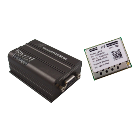
Operating Manual
Pico Series P2400
Miniature 2.4 GHz Wireless Mode (OEM & Enclosed Models)
Document: Pico Series P2400 Operating Manual.v1.0.0
Date: December 2016
Firmware: v1.012
150 Country Hills Landing NW
Calgary, Alberta
Canada T3K 5P3
Phone: (403) 248-0028
Fax: (403) 248-2762
www.microhardcorp.com
Advertisement
Table of Contents

Related Manuals for Microhard Systems Pico P2400 series


Summary of Contents for Microhard Systems Pico P2400 series
- Page 1 Operating Manual Pico Series P2400 Miniature 2.4 GHz Wireless Mode (OEM & Enclosed Models) Document: Pico Series P2400 Operating Manual.v1.0.0 Date: December 2016 Firmware: v1.012 150 Country Hills Landing NW Calgary, Alberta Canada T3K 5P3 Phone: (403) 248-0028 Fax: (403) 248-2762 www.microhardcorp.com...
- Page 2 Warranty Microhard Systems Inc. warrants that each product will be free of defects in material and workmanship for a period of one (1) year for its products. The warranty commences on the date the product is shipped by Microhard Systems Inc. Microhard Systems Inc.’s sole liability and responsibility under this warranty is to repair or replace any product which is returned to it by the Buyer and which Microhard Systems Inc.
- Page 3 An idea or suggestion to improve efficiency or enhance usefulness. Copyright and Trademarks ©2016 Microhard Systems Inc. All rights reserved. Adaptation, or translation of this manual is prohib- ited without prior written permission of Microhard Systems Inc, except as allowed under the copyright laws.
- Page 4 WARNING: Changes or modifications not expressly approved by Microhard Systems Inc. could void the user’s authority to operate the equipment. This device has been tested with UFL to Reverse Polarity SMA connectors with the antennas listed in Appendix A When integrated in OEM products, fixed antennas require installation preventing end-users from replacing them with non-approved antennas.
- Page 5 WARNING: Les changements ou modifications non expressément approuvés par Microhard Systems Inc. pourraient annuler l'autorité de l'utilisateur à utiliser l'équipement . Ce dispositif a été testé avec MCX et connecteurs SMA à polarité inverse sur les antennes répertoriées à l'annexe A Lorsqu'il est intégré...
- Page 6 Revision History Revision Description Initials Date First Release December 2016 © Microhard Systems Inc. Confidential...
-
Page 7: Table Of Contents
Operating Modes / Unit Types...................... 44 3.3.2 Configuration Using Factory Defaults ................... 47 3.3.3 Unit Addressing ..........................51 3.3.4 Retransmissions ........................... 51 3.3.5 Network Synchronization ......................51 3.3.6 TDMA ............................52 3.3.7 Peer-to-Peer..........................54 3.3.8 Everyone-to-Everyone ......................... 55 © Microhard Systems Inc. Confidential... - Page 8 Packet Retry Limit ........................70 S214 Diagnostics Packet Retransmission ................... 70 S217 Protocol Type ..........................70 S238 Hopping Mode ..........................70 S244 Channel Request Mode ......................71 S248 Sync Timeout ..........................71 S251 Master Hop Allocation Timeout ....................71 © Microhard Systems Inc. Confidential...
- Page 9 Appendix D: AT Command Firmware Upgrade ..................81 Appendix E: Development Board Serial Interface ................... 82 Appendix F: Reference Design Schematic....................83 Appendix G: Pico-MHX Adapter Card ....................... 84 Appendix H: Approved Antennas ......................86 © Microhard Systems Inc. Confidential...
-
Page 10: Overview
When properly configured and installed, long range communications at very high speeds can be achieved. Pico P2400 Series modules are a 2.4 GHz Frequency Hopping modem, providing flexible wireless data transfer between most equipment types which employ a serial interface. The modem type of the module is software selectable using AT commands. -
Page 11: Specifications
5% to 95% non-condensing Mechanical Dimensions: OEM: 26.5mm X 33mm X 3.5mm ENC: 57mm X 95mm X 38mm Weight: OEM: 5 grams ENC: 120 grams Connectors: Antenna: OEM: UFL ENC: RP-SMA Data: OEM: 80 Pin/Pad SMT ENC: DB9 © Microhard Systems Inc. Confidential... - Page 12 276.4 -105 FCC/IC -103 FCC/IC 19.2 100mW -115 FCC/IC/CE 100mW -110 FCC/IC/CE 115.2 100mW -109 FCC/IC/CE 172.8 100mW -108 FCC/IC/CE 230.4 100mW -106 FCC/IC/CE 276.4 100mW -105 FCC/IC/CE 100mW -103 FCC/IC/CE Table 1-1: P2400 Specifications © Microhard Systems Inc. Confidential...
-
Page 13: Hardware Description
The Microhard development board can provide a convenient evaluation platform to test and design with the module. (Contact Microhard Systems for details) Any P2400 Series module may be configured as a Master, Repeater or Remote in a PTP or PMP Topology. -
Page 14: Mechanical Drawing
Due to manufacturing methods additional PCB material may be present on the corners that cannot be removed. Designs should allow for a small tolerance of this additional material, ± 0.25mm Drawing 2-1: P2400 OEM Mechanical © Microhard Systems Inc. Confidential... -
Page 15: Recommended Solder Mask (Pad Landing)
2.0 Hardware Description 2.1.1 Recommended Solder Mask (Pad Landing) 22.35 0.99 30.02 28.70 34.34 Detail 19.86 27.99 Detail 0.81 Units: millimeters 1.27 1.83 Drawing 2-2: P2400 Recommended Solder Mask © Microhard Systems Inc. Confidential... -
Page 16: Recommended Solder Paste Pattern
Drawing 2-3: P2400 Recommended Solder Paste 2.1.3 OEM Connectors Antenna All P2400 OEM Modules use an UFL connector for the antenna connection. Data The interface to the P2400 OEM module is a tight integration using 80 pad SMT connections. © Microhard Systems Inc. Confidential... -
Page 17: Smt Temperature Profile
The P2400 OEM modules must be baked before mounting, the following baking instruction should be fol- lowed for the best results: Minimum of 8 to 12 hours at 125°C +/- 5°C for high-temperature device containers. Unused modules should be stored at ≤ 10% RH © Microhard Systems Inc. Confidential... -
Page 18: Pin Descriptions
(1, 25, 41, and 65) are printed directly on the bottom of the PCB for easy identification. — 3.6V max) unless otherwise specified. A full description of the connections and function of each pin is provided on the pages that follow. © Microhard Systems Inc. Confidential... - Page 19 32 Data Terminal Ready. Active low input. Serial DCD 33 Data Carrier Detect. Active low output. Serial RTS 34 Request To Send. Active low input. USR SCK 35 *Currently Not Supported. For Future Expansion* Table 2-1: Pico Series Pin Description © Microhard Systems Inc. Confidential...
- Page 20 Control RxD 37 Diagnostics receive data. Logic level input from a PC to the module. Used for Diagnostics Protocol, contact Microhard Systems for documentation. Control TxD 38 Diagnostics transmit data. Logic level output from module to a PC. Used for Diagnostics Protocol, contact Microhard Systems for documentation.
-
Page 21: Minimum Connection Requirements
3.3 - 3.6V 63 64 Antenna Serial TxD Optional Driver Serial RxD P2400 GND Pins 1 17 25 26 39 40 41 65 66 67 78 79 80 Drawing 2-5: P2400 Minimum Connection Block Diagram © Microhard Systems Inc. Confidential... -
Page 22: Electrical Characteristics
The loading conditions used for pin parameter measurement are shown in Figure 2-1. 2.4.1.4 Pin Input Voltage The input voltage measurement on a pin of the Pico is described in Figure 2-2. Pico pin Pico pin Figure 2-1 Pin Loading Conditions Figure 2-2 Pin Input Voltage © Microhard Systems Inc. Confidential... -
Page 23: Absolute Maximum Ratings
Pico Series. Symbol Ratings Unit External radio supply voltage. External digital supply voltage. Table 2-5 Operating Conditions Voltage Characteristics The modem will not be able to transit at full power if V is less than 3.6VDC. © Microhard Systems Inc. Confidential... -
Page 24: Current Characteristics
Weak pull-down equivalent resistor I/O pin capacitance Hysteresis voltage between Schmitt trigger switching levels. Based on characterization, not tested in production. Pull-up and pull-down resistors can be used on input/output pins. Table 2-7 I/O Static Characteristics © Microhard Systems Inc. Confidential... - Page 25 Output high to low fall time f(IO)out CL = 50 pF Output low to high level rise time r(IO)out Pulse width of external signals used as EXTlpw interrupts. Table 2-9 Input / Output AC Characteristics © Microhard Systems Inc. Confidential...
-
Page 26: 12-Bit Adc Characteristics
Conversion voltage range External input impedance kΩ Table 2-11 12-bit ADC Characteristics Symbol Parameter Test Conditions Unit Total unadjusted error Offset error Gain error = 25 Differential linearity error Integral linearity error Table 2-12 ADC Accuracy © Microhard Systems Inc. Confidential... - Page 27 2.0 Hardware Description ADC Accuracy Characteristics [1LSB = 3.0/4096] IDEAL Figure 2-4 ADC Accuracy Characteristics © Microhard Systems Inc. Confidential...
-
Page 28: P2400 To N2420 Pin-Outs
Positive voltage supply voltage for the digital section of the module (3.3V). 51,53,55,57,59 63,64 Positive voltage supply voltage for the radio module (3.3V). Vcc2 75,76,77 N/A *Reserved for future use.* Table 2-13: P2400 to Nano n2420 Pin Description © Microhard Systems Inc. Confidential... -
Page 29: P2400 Enclosed
RS232/RS485 Data Interface RSSI LED Indicators (Green) TX/RX LED Indicators (Red/Green) CONFIG Button Antenna USB Port (Internal Serial to USB (Diagnostics Port)) I/O pins (Future Development) Image 2-4: P2400 Enclosed © Microhard Systems Inc. Confidential... -
Page 30: P2400 Enclosed Dimensional Drawings
2.6.1 P2400 Enclosed Dimensional Drawings 78.48 12.00 49.00 65.40 Drawing 2-6: P2400 Top View 46.00 26.00 49.00 Drawing 2-7: P2400 Enclosed End Views Drawing 2-8: P2400 Enclosed Side View Notes: The dimension unit is mm. © Microhard Systems Inc. Confidential... -
Page 31: P2400-Enc Mounting Bracket (Optional)
2.6.2 P2400 Enclosed Mounting Bracket (Order Option) Drawing 2-6: P2400 –ENC Mounting Bracket Front/Rear (Shown optional TS35 DIN Rail Mount) 47.4 20.1 12.5 65.2 45.0 54.0 12.5 17.2 12.2 20.1 30.0 23.7 Notes: The dimension unit is mm. © Microhard Systems Inc. Confidential... -
Page 32: Connectors & Indicators
DATA - during sync. Remote Cycling with 300ms ON time acquisition DATA - when Remote ON while synced ON when 1-3 ON in proportion to signal synchronized transmitting strength received from Master/ Repeater Table 2-14: LED Operation © Microhard Systems Inc. Confidential... - Page 33 Vin+/Vin– is used to power the unit. The input Voltage range is 9-30 does not provide Vdc. proper voltage may Vin+ Vin- damage the modem. IO-1 IO-2 IO-1 / IO-2 Programmable I/O. Not currently supported in firmware. Future Development. RP-SMA Female Bulkhead Antenna connector. © Microhard Systems Inc. Confidential...
-
Page 34: Configuration
AT&V will display the current configuration, and the registers can be queried using the ATSXXX=? Command where XXX = the register number. Help is available using the ATSXXX /? Command. Any and all changes must be written to NVRAM using the AT&W command. © Microhard Systems Inc. Confidential... -
Page 35: Data Mode
Available LED indica- tions can provide an indication of the data exchange (TX and RX LEDs). To enter DATA mode from COMMAND mode, enter the command: ATA [Enter] © Microhard Systems Inc. Confidential... -
Page 36: Network Type
Example: Channel 75 @ 172 kbps = 2401.600 +((75-1) x 0.280) MHz 2401.600 + (74 x 0.280) MHz 276.4 2401.600 + 20.72 MHz 345.6 2422.32 MHz or 2.42232 GHz Table 3-1: Link Rate & BW © Microhard Systems Inc. Confidential... -
Page 37: Point To Point Network
The Master controls the flow of data through the system; all data passes through it. The diagram below shows a unit configured as a Master. Coverage Master Area Slave Master Drawing 3-2: Point to Point Master © Microhard Systems Inc. Confidential... - Page 38 Drawing 3-4: Point to Point Slave Units can be configured to perform the various roles discussed by setting register S101 as follows: ATS101 = 0 Master ATS101 = 1 Repeater ATS101 = 2 Slave (Remote) © Microhard Systems Inc. Confidential...
-
Page 39: Configuration Using Factory Defaults
Point to Point configuration. There may also be additional registers such as the Network ID that are recommended to be changed. Each PTP Network must have a unique network ID. This can be changed using register S104: Network Address. Image 3-5: Frequency Hopping Factory Defaults © Microhard Systems Inc. Confidential... - Page 40 Remember, when registers are changed the values must be written to NVRAM using the AT&W com- mand. To switch from command mode to data mode (online mode), the ATA command can be issued. © Microhard Systems Inc. Confidential...
- Page 41 Each unit in a Network must have the same Network Address. To change the Network Address, the ATS104=XXXXXXX command can be used. K) S118 If the slave is to connect through a repeater, enter the unit address of the repeater here. © Microhard Systems Inc. Confidential...
- Page 42 Slave’s RSSI LEDs will indicate that it is ‘scanning’ for its immediate upstream unit; place the Repeater online and the Slave will quickly acquire it. If the Master is taken offline, both the Repeater and Slave will begin to scan. © Microhard Systems Inc. Confidential...
-
Page 43: Retransmissions
Several hops can go by without receiving a sync packet, and this is completely normal. If this value is set too high, the unit will assume for a long time that the network is still out there, when especially in mobile applications, it may not be. © Microhard Systems Inc. Confidential... -
Page 44: Point To Multipoint Network
The diagram below shows a unit configured as a Master. Coverage Master Area Slave Slave Master Slave Drawing 3-2: Point to Multipoint Master © Microhard Systems Inc. Confidential... - Page 45 Local connection between the modems would be a ‘null modem’ cable. Each modem would require its own antenna; careful consideration should be given with respect to antenna placement and modem configuration. Master Coverage Area Slave Slave Master Repeater Repeaters Coverage Area Repeater Slave Slave Drawing 3-3: Point to Multipoint Repeater © Microhard Systems Inc. Confidential...
- Page 46 ATS101 = 1 Repeater ATS101 = 2 Slave (Remote) The next section discussed using Factory Default commands to configure the various types of units that are available in a Point to Multipoint network, simplifying the configuration process. © Microhard Systems Inc. Confidential...
-
Page 47: Configuration Using Factory Defaults
Point to Multipoint configuration. There may also be additional registers such as the Network ID that are recommended to be changed. Each PMP Network must have a unique network ID. This can be changed using register S104: Network Address. Image 3-4: Frequency Hopping Factory Defaults © Microhard Systems Inc. Confidential... - Page 48 Remember, anytime registers are changed the values must be written to NVRAM using the AT&W com- mand. To switch from command mode to data mode (online mode), the ATA command can be issued. © Microhard Systems Inc. Confidential...
- Page 49 Each unit in a Network must have the same Network Address. To change the Network Address, the ATS104=XXXXXXX command can be used. K) S118 If the slave is to connect through a repeater, enter the unit address of the repeater here. © Microhard Systems Inc. Confidential...
- Page 50 Each unit in a Network must have the same Network Address. To change the Network Address, the ATS104=XXXXXXX command can be used. K) S118 If the repeater is to connect through another repeater, enter the unit address of the repeater here. © Microhard Systems Inc. Confidential...
-
Page 51: Unit Addressing
Several hops can go by without receiving a sync packet, and this is completely normal. If this value is set too high, the unit will assume for a long time that the network is still out there, when especially in mobile applications, it may not be. © Microhard Systems Inc. Confidential... -
Page 52: Tdma
The default Registered Slaves list consists of 8192 entries (0-8191), populated with Unit Addresses of 2 thru 8193 respectively. On the following page is an example to illustrate basic TDMA operation. For an actual deployment, ap- plication-specific parameters must be considered and other various modem configuration options opti- mized accordingly. © Microhard Systems Inc. Confidential... - Page 53 Master does not receive the message from the Slave indicating that it has sent all of its data, so the Master will wait for the value of S251 (3 hops) for such a message from the Slave before moving on to begin the cycle again at UA 3. © Microhard Systems Inc. Confidential...
-
Page 54: Peer-To-Peer
ATA command The Master will broadcast (actually ‘re-broadcast’) the data incoming to it from both Slaves to all (2) Slaves; one Slave’s data has a destination being the other Slave and vice versa. © Microhard Systems Inc. Confidential... -
Page 55: Everyone-To-Everyone
Unit Address (S105) to a unique number (range: 2-65534) change the Destination Address to 65535 (the broadcast address) save the change using the AT&W command go online with the ATA command © Microhard Systems Inc. Confidential... -
Page 56: Register/Command Reference
Therefore, to calculate the frequency of channel n: (BW = Channel Bandwidth in MHz) Freq channel n = 2401.6+ ((n-1) x BW) MHz. Identification The I command returns information about the P2400. Product Code Product Identification (Firmware Version) Firmware Date Firmware Copyright Firmware Time Factory-Configured Options listing © Microhard Systems Inc. Confidential... -
Page 57: Login At Login
= stop frequency in MHz (including 0-6 decimal places) stop = step increment in kHz (from 1-1000) = dwell time in ms (from 1-1000) Example: ATN 2402.250 2420.250 25 100 Note: Be sure to enter spaces as shown in the format detailed above. © Microhard Systems Inc. Confidential... -
Page 58: Fn Load Factory Default Configuration
&F11 FH Master Fast P2P no Time ACK &F12 FH Master Fast PP no Time ACK &F15 FH Master WL &F16 FH Slave WL &F18 FH Master Fast TDMA &F19 FH Slave Fast TDMA &F100 - Reset Hopping Modes © Microhard Systems Inc. Confidential... -
Page 59: Frequency Restriction (Fhss)
Repeaters in the network into each modem in the network.) Having entered ‘1’, the modem prompts A T & H 0 f e a t u r e configure the modem to for the first restricted frequency to be entered. avoid them. Image 4-2: Unit Address © Microhard Systems Inc. Confidential... -
Page 60: Repeater Registration (Fhss)
Stores active configuration into the modem’s non-volatile memory. Any changes made to the Pico Series must be written to NVRAM using the AT&W command (AT&WA will write the changes & set unit in online mode) © Microhard Systems Inc. Confidential... -
Page 61: Settings (S) Registers
Escape character. If >127, escape feature is disabled. Modification of Values this register may be necessary when connecting the modem to a telephone modem where the +++ character string may result in any ASCII value + (decimal 43) undesired consequences. © Microhard Systems Inc. Confidential... -
Page 62: Operating Mode
- to operate in the same area without the network. Do this for an possibility of undesired data exchange between networks. added measure of security and to differentiate your network from others which may be operating nearby. © Microhard Systems Inc. Confidential... -
Page 63: Unit Address
(EIRP). The sum (in (160) (630) the minimum value required to maintain an adequate system fade dBm) of the transmitted (200) (800) margin. power, the cabling loss, (1W) (250) and the antenna gain (320) cannot exceed 36dBi. © Microhard Systems Inc. Confidential... -
Page 64: Hop Interval
When forcing a module to Command Mode the data port will temporarily communicate at the default value. When the P2400 is 10 7O2 retuned to Data Mode, the serial port settings are returned to those specified in S102 and S110. © Microhard Systems Inc. Confidential... -
Page 65: Packet Min Size
In a TDMA-type system, S115 may be set to 1 as the Remotes are not able to request a transmission channel: the Master polls each Remote for data. © Microhard Systems Inc. Confidential... -
Page 66: S116 Character Timeout
Command Mode and reply with ‘OK’. The terminal baud rate must be enabled set to 9600bps. If an incorrect character is entered, the modem will immediately go into Data mode. The default setting is 0: The modem will promptly go into Data Mode upon power-up. © Microhard Systems Inc. Confidential... -
Page 67: Rssi From Uplink/Master (Dbm)
(P2P) or between all units (Everyone-2-Everyone - E2E). S139 Compatible_21 at 345 If this register is set the P2400 will be compatible with the MHX2421 Values operating at a link rate of 345kbps. 0 - Disabled 1 - Enabled © Microhard Systems Inc. Confidential... -
Page 68: Destination Address
A value of 2 results in the Master going into quick sync mode when it initially comes online and then remaining in that mode for the duration specified in S151 (fast sync timeout) and then return to normal sync mode. © Microhard Systems Inc. Confidential... -
Page 69: Fast Sync Timeout
Information rate 0.75, corrects 1 out of 31 bits Binary BCH (47,36) Information rate 0.75, corrects 2 bits Golay (23, 12, 7) Information rate 0.5, corrects 3 bits Reed-Solomon (15,11) Information rate 0.687, corrects 2 nibbles © Microhard Systems Inc. Confidential... -
Page 70: Crc Check On Diag Port
S238 controls the modem either hopping 0 - Hopping on pattern on pattern or on frequency table. 1 - Hopping on frequency table 2 - Hopping on channel 3 - Hopping on frequency © Microhard Systems Inc. Confidential... -
Page 71: Channel Request Mode
Master will wait for a Remote to either (a) begin to send hops data or (b) indicate that it has completed sending all of its data, prior to 1-254 the Master sequencing to the next Remote to be given permission to transmit. © Microhard Systems Inc. Confidential... -
Page 72: Serial Interface Commands
Controls the module’s DSR line and determines when it is active. Values Software flow control (XON/XOFF) is not 0 - DSR always on supported. 1 - DSR = 0 in data mode, 1 command mode © Microhard Systems Inc. Confidential... -
Page 73: Installation
‘numbers’ for radio path calculations. Fortunately, the Pico Series features the maximum available transmit power combined with exceptional receive sensitivity - two ‘numbers’ which will produce the most favorable path calculation results. © Microhard Systems Inc. Confidential... - Page 74 Frequency Restriction (Hopping Zones) is a built-in feature which may be utilized to avoid specific frequencies or ranges of frequencies; the Spectrum Analyzer function may be used to identify areas of potential interference. Cavity filters are also available if required: contact Microhard Systems Inc. for further information. © Microhard Systems Inc. Confidential...
-
Page 75: Path Calculation
Tx power = 30dBm Tx antenna gain = 6dBi System Gain = [30+(6-2)+(3-2)+108]dB Tx cable/connector loss = 2dB = [30+4+1+108]dB Rx antenna gain = 3dBi = 143dB. Rx cable/connector loss = 2dB Rx sensitivity = -108dBm © Microhard Systems Inc. Confidential... -
Page 76: Installation Of Antenna System Components
The network topology, application, and path calculation are all taken into considera- tion when selecting the various antenna types to be used in a radio network deploy- ment. © Microhard Systems Inc. Confidential... -
Page 77: Coaxial Cable
Paging towers and cellular base stations in close proximity to the P2400’s antenna can desensitize the receiver. Microhard Systems Inc.’s external cavity filter eliminates this problem. The filter has two N-female connectors and should be connected inline at the interface to the RF equipment. -
Page 78: Appendix A: At Command Quick Reference
Sxxx /? Display S Register Help Text -where xxx is the S register’s number, this command will result in displaying the available settings of that register. Not all registers have help text. © Microhard Systems Inc. Confidential... -
Page 79: Appendix B: Settings (S) Register Quick Reference
Golay (23,12,7) Output Power Level Reed-Solomon (15,11)* 20-30dBm 30* (1W) S244 Channel Access Mode 0 - Channel request (default), 1 - TDMA, 2 - Fast TDMA 3 - On GPS index, 4 - Adaptive TDMA © Microhard Systems Inc. Confidential... -
Page 80: Appendix C: At Utility Firmware Upgrade Procedure
6. The utility will establish a connection to the module and load the firmware. Once com- plete, a message will be display at the bot- tom of the utility window indicating that the process succeeded. Image C-1: Firmware Upgrade © Microhard Systems Inc. Confidential... -
Page 81: Appendix D: At Command Firmware Upgrade
Modem returns the “ERROR” response when the 20s time-out is ex- pired. The approximate duration on this step is 30s. After the flash upgrade finishes, the modem reboots and it is ready to work. © Microhard Systems Inc. Confidential... -
Page 82: Appendix E: Development Board Serial Interface
RX line, and receives on TX. “DCE” and “module” are often synonymous since a module is typically a DCE device. “DTE” is, in most applications, a device such as a host microprocessor. © Microhard Systems Inc. Confidential... -
Page 83: Appendix F: Reference Design Schematic
Appendix F: Pico Development Board Schematic © Microhard Systems Inc. Confidential... -
Page 84: Appendix G: Pico-Mhx Adapter Card
(1,20,21,40) are printed directly on the PCB for reference. 3.3V or 5V Select VClock !Shutdown !Bootpgm_Mode Diag TxD USR_AN0 Diag RxD !WAKEUP_usr Rx/SYNC_LED !Config TxMODE_LED Pin-Out !Reset RSSI3_LED (Top View) VBat RSSI2_LED Sleep_Mode RSSI1_LED RING USR_1 USR_2 USR_3 MHX Series Pin-Out (Top View) © Microhard Systems Inc. Confidential... - Page 85 Appendix G: Pico-MHX Adapter Card (Page 2 of 2) © Microhard Systems Inc. Confidential...
-
Page 86: Appendix H: Approved Antennas
WARNING: Changes or modifications not expressly approved by Microhard Systems Inc. could void the user’s authority to operate the equipment. This device has been tested with UFL connectors with the antennas listed in Appendix A When integrated in OEM products, fixed antennas require installation preventing end-users from replacing them with non-approved antennas. - Page 87 150 Country Hills Landing NW Calgary, Alberta Canada T3K 5P3 Phone: (403) 248-0028 Fax: (403) 248-2762 www.microhardcorp.com...
Need help?
Do you have a question about the Pico P2400 series and is the answer not in the manual?
Questions and answers