Table of Contents
Advertisement
Quick Links
Advertisement
Table of Contents

Related Manuals for Microhard Systems P900


Summary of Contents for Microhard Systems P900
- Page 1 Operating Manual Pico Series - P900 900MHz Spread Spectrum Modem Document: Pico Series P900 Operating Manual.v1.8.7 Date: June 2016 Firmware: v1.19 150 Country Hills Landing NW Calgary, Alberta Canada T3K 5P3 Phone: (403) 248-0028 Fax: (403) 248-2762 www.microhardcorp.com...
-
Page 2: Microhard Systems Inc. Confidential
Warranty Microhard Systems Inc. warrants that each product will be free of defects in material and workmanship for a period of one (1) year for its products. The warranty commences on the date the product is shipped by Microhard Systems Inc. Microhard Systems Inc.’s sole liability and responsibility under this warranty is to repair or replace any product which is returned to it by the Buyer and which Microhard Systems Inc. - Page 3 Point to Remember Highlights a key feature, point, or step which is noteworthy. Keeping these in mind will simplify or enhance device usage. An idea or suggestion to improve efficiency or enhance usefulness. © Microhard Systems Inc. Confidential...
-
Page 4: Regulatory Requirements
WARNING This device can only be used with antennas designed for use with 900 MHz products. Please contact Microhard Systems Inc. if you need more information or would like to order an antenna. MAXIMUM EIRP WARNING FCC Regulations allow up to 36dBm Effective Isotropic Radiated Power (EIRP). -
Page 5: Revision History
RS485 driver. Update for firmware v1.14 - Removed AT&S3, Added AT&K1 to use Aug 2015 CTS to control the Transmitter of RS485 driver chip. Added P900-ENC drawings, connectors and LED descriptions Sept 2015 1.81 Added P900-ENC Optional mounting Bracket. Misc updates. -
Page 6: Table Of Contents
Voltage Characteristics ....................22 2.4.3.3 Current Characteristics ....................23 2.4.3.4 IO Port Characteristics .....................24 2.4.3.5 12-bit ADC Characteristics ..................25 2.5 P900 to n920 Pin-outs......................27 P900 Enclosed ..........................28 2.6.1 P900 Enclosed Mechanical Drawings ..................29 2.6.2 P900 Enclosed Mounting Bracket (Optional) ................30 2.6.3 P900 Enclosed Connectors &... - Page 7 Distance from Master (PP/PMP) ....................84 Enable S105 as MAC (Mesh) ....................84 S101 Operating Mode (Mesh) ......................85 S101 Operating Mode (PP/PMP) ....................85 S102 Serial Baud Rate ........................85 S103 Wireless Link Rate ........................85 S104 Network ID/Address ......................86 © Microhard Systems Inc. Confidential...
- Page 8 Master Ch. Request Timeout (PMP) ..................97 S235 PP Routing TTL (PP) ......................97 S236 Max Buffer Out Storage ......................97 S244 Channel Access Mode......................97 S245 Cost of Hop in Mesh ......................97 S247 Country Code (Read Only) ....................97 S248 Sync Timeout ........................98 © Microhard Systems Inc. Confidential...
- Page 9 Appendix D: AT Command Firmware Upgrade .................. 108 Appendix E: Development Board Serial Interface ................109 Appendix F: Pico Reference Schematic..................... 110 Appendix G: Pico-MHX Adapter Board ....................111 Appendix H: Approved Antennas ....................... 113 © Microhard Systems Inc. Confidential...
-
Page 10: Overview
- transparent remote diagnostics and online network control ease of installation and configuration - the P900 utilizes a subset of standard AT- style commands, similar to those used by traditional telephone line modems 3.3V logic level compatibility 902-928 MHz, which is license-free within North America;... -
Page 11: Specifications
1.0 Overview 1.2 Pico Series P900 Specifications Electrical/General Frequency: 902 - 928 MHz Spreading Method: Frequency Hopping Band Segments: Selectable via Freq. Zones Error Detection: 32 bits of CRC, ARQ Data Encryption: 128, 196 or 256-bit AES Encryption (Requires export (Optional) permit outside US and Canada.) -
Page 12: Hardware Description
2.0 Hardware Description The Pico Series P900 Modem modules are available as a low cost OEM module. This OEM version supplies all the required raw signals to allow the unit to be tightly integrated into applications to efficiently maximize space and power requirements. The Microhard development board can provide a convenient evaluation platform to test and design with the module. -
Page 13: Oem Mechanical Drawing
2.0 Hardware Description 2.1 Mechanical Drawings The P900 OEM Modules have an extremely small form factor as seen in Drawing 3-3 below. 3.68 2.31 0.80 Detail 1.27 1.18 26.5 1.50 3.41 22.35 Ground Plane 30.01 28.70 Detail 2.16 Bottom View 19.85... -
Page 14: Recommended Solder Mask (Pad Landing)
2.0 Hardware Description 2.1.1 Recommended Solder Mask (Pad Landing) 22.35 0.99 30.02 28.70 34.34 Detail 19.86 27.99 Detail 0.81 Units: millimeters 1.27 1.83 Drawing 2-2: P900 Recommended Solder Mask © Microhard Systems Inc. Confidential... -
Page 15: Recommended Solder Paste Pattern
Drawing 2-3: P900 Recommended Solder Paste 2.1.3 OEM Connectors Antenna All P900 OEM Modules use an UFL connector for the antenna connection. Data The interface to the P900 OEM module is a tight integration using 80 pad SMT connections. © Microhard Systems Inc. Confidential... -
Page 16: Smt Temperature Profile
Table 2-2: Oven Temperature Profile 2.1.5 SMT Baking Instructions (MSL) The P900 OEM modules must be baked before mounting, the following baking instruction should be fol- lowed for the best results: Minimum of 8 to 12 hours at 125°C +/- 5°C for high-temperature device containers. -
Page 17: Oem Pin Descriptions
Vbat LED TX Drawing 2-5: Pico P900 80-pin OEM Connection Info The above drawing depicts a top view of the P900-OEM Module. The corner pads (1, 25, 41, Inputs and outputs are 3.3V nominal (3.0V min and 65) are printed directly on the bottom of the PCB for easy identification. - Page 18 32 Data Terminal Ready. Active low input. Serial DCD 33 Data Carrier Detect. Active low output. Serial RTS 34 Request To Send. Active low input. 35 *Currently Not Supported. For Future Expansion* USR SCK Table 2-3: Pico Series Pin Description © Microhard Systems Inc. Confidential...
- Page 19 Table 2-3: Pico Series Pin Description (continued) All serial communications signals are logic level (0 and 3.3V). DO NOT connect RS-232 level (+12, -12VDC) signals to these lines without shifting the signals to logic levels. © Microhard Systems Inc. Confidential...
-
Page 20: Oem Minimum Connection Requirements
2.3 Minimum Connection Requirements 3.3V 63 64 Antenna Serial TxD Optional Driver Serial RxD P900 GND Pins 1 17 25 26 39 40 41 65 66 67 78 79 80 Drawing 2-6: P900 Minimum Connection Block Diagram © Microhard Systems Inc. Confidential... -
Page 21: Electrical Characteristics
The loading conditions used for pin parameter measurement are shown in Figure 2-1. 2.4.1.4 Pin Input Voltage The input voltage measurement on a pin of the Pico is described in Figure 2-2. Pico pin Pico pin Figure 2-1 Pin Loading Conditions Figure 2-2 Pin Input Voltage © Microhard Systems Inc. Confidential... -
Page 22: Absolute Maximum Ratings
Pico Series. Symbol Ratings Unit External radio supply voltage. External digital supply voltage. Table 2-7 Operating Conditions Voltage Characteristics The modem will not be able to transit at full power if V is less than 3.3VDC. © Microhard Systems Inc. Confidential... -
Page 23: Current Characteristics
Weak pull-down equivalent resistor I/O pin capacitance Hysteresis voltage between Schmitt trigger switching levels. Based on characterization, not tested in production. Pull-up and pull-down resistors can be used on input/output pins. Table 2-9 I/O Static Characteristics © Microhard Systems Inc. Confidential... -
Page 24: Io Port Characteristics
Output high to low fall time f(IO)out CL = 50 pF Output low to high level rise time r(IO)out Pulse width of external signals used as EXTlpw interrupts. Table 2-11 Input / Output AC Characteristics © Microhard Systems Inc. Confidential... -
Page 25: 12-Bit Adc Characteristics
Conversion voltage range External input impedance kΩ Table 2-13 12-bit ADC Characteristics Symbol Parameter Test Conditions Unit Total unadjusted error Offset error Gain error = 25 Differential linearity error Integral linearity error Table 2-14 ADC Accuracy © Microhard Systems Inc. Confidential... - Page 26 2.0 Hardware Description ADC Accuracy Characteristics [1LSB = 3.0/4096] IDEAL Figure 2-4 ADC Accuracy Characteristics © Microhard Systems Inc. Confidential...
-
Page 27: P900 To N920 Pin-Outs
2.5 P900 to Nano n920 Pin-Outs The following table shows a pin-out comparison between the P900 and the n920. This table may be useful for customers who current have the n920 who wish to migrate to the P900 platform. Pin Name P900 Pin No. -
Page 28: P900 Enclosed
OEM module is not required, but a modem with a small footprint is still required. The P900 Enclosed can also be used to quickly evaluate the features and performance of the P900 modems. The P900 Enclosed provides quick access to several of the interfaces of the P900, such as: Input Power (9-30VDC) ... -
Page 29: P900 Enclosed Mechanical Drawings
2.6.1 P900 Enclosed Dimensional Drawings 78.48 12.00 49.00 65.40 Drawing 2-7: P900 Top View 46.00 26.00 49.00 Drawing 2-8: P900 Enclosed End Views Drawing 2-9: P900 Enclosed Side View Notes: The dimension unit is mm. © Microhard Systems Inc. Confidential... -
Page 30: P900 Enclosed Mounting Bracket (Optional)
2.0 Hardware Description 2.6.2 P900 Enclosed Mounting Bracket (Order Option) Drawing 2-10: P900 –ENC Mounting Bracket Front/Rear (Shown optional TS35 DIN Rail Mount) 47.4 20.1 12.5 65.2 45.0 54.0 12.5 17.2 20.1 12.2 30.0 23.7 Drawing 2-11: P900 –ENC Mounting Bracket Top View Notes: The dimension unit is mm. -
Page 31: P900 Enclosed Connectors & Indicators
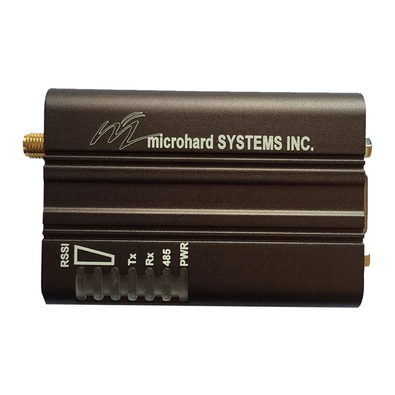
Drawing 2-12: Connectors & LED’s (Top & End) PWR (Blue) This LED will illuminate when the P900 Enclosed is connected to a power source (9-30 VDC) 485 (Blue) This LED will illuminate when the P900 Enclosed Data port is configured as a RS485 port. - Page 32 Vin+ Vin- IO-1 / IO-2 IO-1 IO-2 Programmable I/O. Not currently supported in firmware. Future Development. RP-SMA Female Bulkhead Antenna connector. Caution: Using a power supply that does not provide proper voltage may damage the modem. © Microhard Systems Inc. Confidential...
-
Page 33: Mesh Configuration
Configuration/Unit Modes 3.1.1 Command Mode the P900 module is offline (data is not passing through the unit via it’s local data lines or RF communications) if installed in a Development Board, the only LED illuminated will be the blue power LED. -
Page 34: Data Mode
Image 3-3: Command Mode - AT&V Display 3.1.2 Data Mode Data Mode is the normal operational state of all deployed P900 modules. In this mode the module is prepared to exchange data as per its configuration settings. Available LED indications can provide an indication of the data exchange (TX and RX LEDs). -
Page 35: Mesh Network
Mesh network. Mesh Networking generally results in achieving extensive network redundancy. Mesh is enabled by setting register S133 to 2 or 3 (for Mesh with Roaming) (ATS133=2 or ATS133=3, Network Type). Mesh Mesh Mesh Mesh Mesh Mesh Mesh Drawing 3-1: Mesh Network Topology © Microhard Systems Inc. Confidential... -
Page 36: Operating Modes / Unit Types
In a Microhard Mesh Network, there are four unit types or operating modes that are available: the Pri- mary Coordinator, the Secondary Coordinator, the Standby Coordinator, and the Remote. Any P900 module can be configured to perform any of these roles, the paragraphs and diagrams that follow at- tempt to describe the purpose of each unit. - Page 37 Should one unit go offline, another with routing also enabled can continue to provide routing services. The following illustration shows the previous network coverage being extended by adding a secondary coordinator. Secondary Coordinator Primary Mesh Coordinator Mesh P.C. Mesh Mesh Mesh Drawing 3-3: Secondary Coordinator © Microhard Systems Inc. Confidential...
- Page 38 The following illustration shows the Mesh Network with the addition of the Standby Coordinator to pro- vide a backup in an event where the Primary Coordinator cannot perform its duties. Secondary Coordinator Mesh Mesh Primary Coordinator P.C. Standby Coordinator Stand Mesh Mesh Mesh Drawing 3-4: Standby Coordinator © Microhard Systems Inc. Confidential...
-
Page 39: Configuration Using Factory Defaults
AT&F3 Mesh Secondary Coordinator The following screen shots will illustrate how the commands are used and also highlight the key regis- ters that have been changed, or need to be changed for a successful deployment. © Microhard Systems Inc. Confidential... -
Page 40: At&F1 Primary Coordinator
Remember, anytime registers are changed the values must be written to NVRAM using the AT&W com- mand. To switch from command mode to data mode (online mode), the ATA command can be issued. © Microhard Systems Inc. Confidential... -
Page 41: At&F2 - Mesh Remote
Remember, anytime registers are changed the values must be written to NVRAM using the AT&W com- mand. To switch from command mode to data mode (online mode), the ATA command can be issued. © Microhard Systems Inc. Confidential... -
Page 42: At&F3 Secondary Coordinator
Remember, anytime registers are changed the values must be written to NVRAM using the AT&W com- mand. To switch from command mode to data mode (online mode), the ATA command can be issued. © Microhard Systems Inc. Confidential... -
Page 43: Standby Coordinator
Changes Operating Mode to Standby Coordinator. C) S224 Standby Trip Level is used to specify how quickly the P900 will switch from standby mode if sync packets are not received from the Primary. The smaller the value of S224 the longer the Standby Coordinator will wait before assuming the role of the Primary. -
Page 44: Unit Addressing
It can also be viewed using the ATI commands. ATI255 will show the MAC address as well as some additional information seen in the image below. ATI7 will show just the MAC Address. Image 3-9: Retrieving unit MAC Address from ATI255 Output © Microhard Systems Inc. Confidential... -
Page 45: Collision Mitigation
A short hop interval, or reduced number of aloha slots will make the system more immune to outside interference and noise, but at the cost of reduced throughput. © Microhard Systems Inc. Confidential... -
Page 46: Carrier Sense
It is not recommended to adjust the value of S80, unless the environment is well understood. Caution: Setting a value of S81 too low will prevent all communication. © Microhard Systems Inc. Confidential... - Page 47 TX Profile. This allows guaranteed periods of time in which only certain ranked modems can transmit data. The result is reduc- ing or eliminating collisions on the overlapping coverage boundaries. © Microhard Systems Inc. Confidential...
-
Page 48: Tx Profile & Ranking
Profile 3 allocates most of the bandwidth to Rank 1 units with only 2 in 16 frames available for the Rank 0 coordinator. This profile is used in systems with no additional coordinators, where the units send data a majority of the time, with the occasional transmission from the Primary. © Microhard Systems Inc. Confidential... -
Page 49: Retransmissions
- Network ID (S104), Network Type (S133), Forward Error Correction (S158) and - the same number of Aloha Slots (S214), number of Sync Slots (S215). In Mesh without roaming, Hop Pattern (S106) and Hop Zone (S180) must also match. © Microhard Systems Inc. Confidential... - Page 50 Customers located in other regions or government organizations who allow or require more or less entries in the hop pattern may decide that the default value is not appropriate for their sys- tems, and are free to adjust this value. © Microhard Systems Inc. Confidential...
-
Page 51: Routing
- a unit moves, a unit is added, or a unit is removed from the system. When this happens, the routing table(s) must be updated. © Microhard Systems Inc. Confidential... - Page 52 © Microhard Systems Inc. Confidential...
- Page 53 The cost of RSSI is set by the modem based on the measured value between hops. The stronger a signal, the lower its cost as seen in the relationship below. Very High Cost None -100 =110….. RSSI Drawing 3-8: Cost of RSSI vs RSSI © Microhard Systems Inc. Confidential...
- Page 54 (2x10) + 3 + 21 = 44 Path 1 -91Bm (2x10) + 0 +40 = 60 (21)* -52dBm (3x10) + 0 + 6 + 0 = 36 (0)* *Cost of RSSI Drawing 3-8: Routing Path Cost © Microhard Systems Inc. Confidential...
-
Page 55: Hop Pattern
Link Rate Channel (bps) Bandwidth (kHz) Example: Channel 75 @ 172 kbps = 902.4 +((75-1) x 0.250) MHz 57600 902.4 + (74 x 0.250) MHz 902.4 + 18.5 MHz 115200 920.9 MHz 172800 230400 276480 © Microhard Systems Inc. Confidential... - Page 56 Bands can be excluded. Also if multiple systems are being deployed within close proximity, Hop Zones can be used to minimize overlap in the frequencies used to populate the Hopping Pattern. Image 3-11: Hop Zones © Microhard Systems Inc. Confidential...
-
Page 57: Point To Point Configuration
Diagnostic Port. Refer to Section 2: Hardware Description for information related to inter- facing to, or powering the module. To issue AT commands through the Data port, the P900 must first be set into Command Mode as de- scribed below. -
Page 58: Data Mode
‘NO CARRIER OK’ Image 4-2: Command Mode The P900 is now in command mode, and AT commands can be used to configure or query the settings. Entering the AT&V command as shown will show the current configuration as seen below: (The data displayed varies based on network and unit type.) -
Page 59: Point To Point Network
The Master controls the flow of data through the system; all data passes through it. The diagram below shows a unit configured as a Master. Coverage Master Area Slave Master Drawing 4-2: Point to Point Master © Microhard Systems Inc. Confidential... - Page 60 Drawing 4-4: Point to Point Slave Units can be configured to perform the various roles discussed by setting register S101 as follows: ATS101 = 0 Master ATS101 = 1 Repeater ATS101 = 2 Slave (Remote) © Microhard Systems Inc. Confidential...
-
Page 61: Configuration Using Factory Defaults
Point to Point configuration. There may also be additional registers such as the Network ID that are recommended to be changed. Each PTP Network must have a unique network ID. This can be changed using register S104: Network Address. Image 4-4: Factory Defaults © Microhard Systems Inc. Confidential... -
Page 62: At&F10 - Pp Master
Remember, anytime registers are changed the values must be written to NVRAM using the AT&W com- mand. To switch from command mode to data mode (online mode), the ATA command can be issued. © Microhard Systems Inc. Confidential... -
Page 63: At&F11 - Pp Slave/Remote
Secondary Hop Pattern (S206). S118 If the slave is to connect through a repeater, enter the unit address of the repeater here, or set to 65535 for roaming. © Microhard Systems Inc. Confidential... -
Page 64: At&F12 - Pp Repeater
This is the secondary hop pattern which is used to communicate with downstream units. M) S118 The roaming address must be set to the master or repeaters’ address (if more than 1 repeater is used) in which this repeater is to synchronize with. © Microhard Systems Inc. Confidential... -
Page 65: Retransmissions
Several hops can go by without receiving a sync packet, and this is completely normal. If this value is set too high, the unit will assume for a long time that the network is still out there, when especially in mobile applications, it may not be. © Microhard Systems Inc. Confidential... -
Page 66: Hop Pattern
902.4+ ((n-1) x BW) MHz. (bps) Bandwidth (kHz) Example: Channel 75 @ 172 kbps = 902.4 +((75-1) x 0.250) MHz 57600 902.4 + (74 x 0.250) MHz 115200 902.4 + 18.5 MHz 920.9 MHz 172800 230400 276480 © Microhard Systems Inc. Confidential... - Page 67 Bands can be excluded. Also if multiple systems are being deployed within close proximity, Hop Zones can be used to minimize overlap in the frequencies used to populate the Hopping Pattern. Image 4-8: Hop Zones © Microhard Systems Inc. Confidential...
-
Page 68: Point To Multipoint Configuration
Diagnostic Port. Refer to Section 2: Hardware Description for information related to inter- facing to, or powering the module. To issue AT commands through the Data port, the P900 must first be set into Command Mode as de- scribed below. -
Page 69: Data Mode
‘NO CARRIER OK’ Image 5-2: Command Mode The P900 is now in command mode, and AT commands can be used to configure or query the settings. Entering the AT&V command as shown will show the current configuration as seen below: (The data displayed varies based on network and unit type.) -
Page 70: Point To Multipoint Network
The diagram below shows a unit configured as a Master. Coverage Master Area Slave Slave Master Slave Drawing 5-2: Point to Multipoint Master © Microhard Systems Inc. Confidential... - Page 71 Local connection between the modems would be a ‘null modem’ cable. Each modem would require its own antenna; careful consideration should be given with respect to antenna placement and modem configuration. Master Coverage Area Slave Slave Master Repeater Repeaters Coverage Area Repeater Slave Slave Drawing 5-3: Point to Multipoint Repeater © Microhard Systems Inc. Confidential...
- Page 72 ATS101 = 1 Repeater ATS101 = 2 Slave (Remote) The next section discussed using Factory Default commands to configure the various types of units that are available in a Point to Multipoint network, simplifying the configuration process. © Microhard Systems Inc. Confidential...
-
Page 73: Configuration Using Factory Defaults
Point to Point configuration. There may also be additional registers such as the Network ID that are recommended to be changed. Each PMP Network must have a unique network ID. This can be changed using register S104: Network Address. Image 5-4: Factory Defaults © Microhard Systems Inc. Confidential... -
Page 74: At&F7 - Pmp Master
Remember, anytime registers are changed the values must be written to NVRAM using the AT&W com- mand. To switch from command mode to data mode (online mode), the ATA command can be issued. © Microhard Systems Inc. Confidential... -
Page 75: At&F8 - Pmp Slave/Remote
Secondary Hop Pattern (S206). S118 If the slave is to connect through a repeater, enter the unit address of the repeater here. Or set to 65535 for roaming. © Microhard Systems Inc. Confidential... -
Page 76: At&F9 - Pmp Repeater
Should normally be set to the Hopping Pattern of the Master(S106), or if the unit is to communicate through a another repeater, set to match the Secondary Hop Pattern (S206) of that device. S206 This is the secondary hop pattern which is used to communicate with downstream units. © Microhard Systems Inc. Confidential... -
Page 77: Unit Addressing
Several hops can go by without receiving a sync packet, and this is completely normal. If this value is set too high, the unit will assume for a long time that the network is still out there, when especially in mobile applications it may not be. © Microhard Systems Inc. Confidential... -
Page 78: Hop Pattern
902.4+ ((n-1) x BW) MHz. (kHz) Example: Channel 75 @ 172 kbps = 902.4 +((75-1) x 0.250) MHz 57600 902.4 + (74 x 0.250) MHz 115200 902.4 + 18.5 MHz 920.9 MHz 172800 230400 276480 © Microhard Systems Inc. Confidential... - Page 79 Bands can be excluded. Also if multiple systems are being deployed within close proximity, Hop Zones can be used to minimize overlap in the frequencies used to populate the Hopping Pattern. Image 5-8: Hop Zones © Microhard Systems Inc. Confidential...
-
Page 80: Register/Command Reference
If changes were made to the modem’s This is a very useful feature of the P900. ATg or ATG will provide a display of signal levels received within the configuration and it is operating environment and frequency range of the modem under test. ATg averages 256 samples, ATG 16,000. -
Page 81: Login Enable Login Password
To access the menu use the ATM <enter> command. Image 6-2: Mesh Diagnostics Main Menu For more information about the Mesh Menu contact Microhard Systems for a detailed application note. © Microhard Systems Inc. Confidential... -
Page 82: Advanced Spectrum Analyzer
The Advanced Spectrum Analyzer feature provides for a very detailed analysis of a particular area of the radio frequency spectrum within which the P900 operates. The specific start (of scan) and stop frequencies, along with step (increment) size and dwell (on frequency) time are user-definable. -
Page 83: Settings (S) Registers
3: 0x1,0x2,0x2,0x2,0x2,0x2,0x2,0x2,0x1,0x2,0x2,0x2,0x2,0x2,0x2,0x2 S81 (MESH) CS Threshold The P900 uses CSMA (Carrier Sense Multiple Access) to determine if the Values (0 to –255 dBm) channel is available. The Carrier Detect Threshold is used to set the measured level in which the signal is deemed as a valid carrier signal or outside noise or interference (noise floor). -
Page 84: Records Ttl
6.0 Register/Command Reference Records TTL The P900 keeps record of all other modems it has heard from. This information Values (10 to 65535) may be useful to advanced users in system testing and troubleshooting. The RSSI in the records is averaged over the last 8 measurements. Every time a modem is heard from its record is renewed. -
Page 85: Operating Mode (Mesh)
6.0 Register/Command Reference S101 (MESH) Operating Mode The Operating mode defines the role in the network a unit plays. A P900 Values modem may be configured for any role required within a radio network. This is convenient for reasons of familiarity with any/all units, as well as for hardware Slave (Remote) sparing purposes. -
Page 86: Network Id/Address
Values (0 - 49) This register, together with the Network ID and the Hop Zone, determines the Hopping Pattern or table on which the P900 will frequency hop. This register must be set to the hop pattern of the immediate Master/Repeater, unless roaming is used. -
Page 87: Hop Interval
Based device that is connected to the data port. When forcing a module to Command Mode the data port will temporarily communicate at the default value. When the P900 is retuned to Data Mode, the serial port settings are returned to those specified in S102 and S110. -
Page 88: Packet Min Size
The Pico will accumulate data in its buffers until either (a) Maximum Packet size (S112) has been accumulated, or (b) Minimum Packet Size (S111) has been accumulated AND the Character timeout has expired—whichever occurs first. © Microhard Systems Inc. Confidential... -
Page 89: Roaming (Pp/Pmp)
Does not apply to master and primary coordinator. Should normally be disabled to prevent 0 - Disabled (default) accumulation of stale data inside a modem. 1 - Enabled © Microhard Systems Inc. Confidential... -
Page 90: Network Type
Upon wake up the modems will be out on 1 - Enabled sync with the network and need time to re-synchronize. The DSR line can be configured to indicate when the modem is asleep (DSR = 1) and awake (DSR = © Microhard Systems Inc. Confidential... -
Page 91: S144 Sleep Time
0 - Disable (default) Type 1: First 2 bytes - size (high byte first), one byte - RSSI, one reserved byte 1 - Type 1 (0x00), last six bytes - source unit address (high byte first). © Microhard Systems Inc. Confidential... -
Page 92: S158 Forward Error Correction (Fec) Mode
No encryption factory at time of assembly. The use of AES encryption, and export laws governing AES, vary from country to country, contact Microhard Systems AES 128 bit Inc. for more information. -
Page 93: Crc Check On Diag Port
0. It is used in some applications to generate common synchronization on many slaves. With the default setting of 5 and the hop interval of 20ms, each slave will synchronously generate a pulse of approximately 3ms every 100ms. © Microhard Systems Inc. Confidential... -
Page 94: Data Time To Live (Mesh)
Values (0 - 49) This register, together with the Network ID and the Secondary Hop Zone, determines the Secondary Hopping Pattern which a P900 Repeater will use to synchronize and communicate with downstream units. The S106 (Primary Hop Pattern) register must be set to the same value on each repeater/slave that is downstream of this unit. -
Page 95: Protocol Type
Values port. Allows the destination address to be embedded into the data stream, which is automatically stripped by the P900 before transmitting the packet. 0 - Transparent Serial (Default) 1 - Destination Address (DA) is in first six bytes (high byte first) of the packet. -
Page 96: Routing (Mesh)
Used to limit the amount of storage the modem will allocate to incoming user’s data. Each buffer is S112 number of bytes. With S112=256 (default) and S232=200 (default) the modem can store up to 51200 bytes. © Microhard Systems Inc. Confidential... -
Page 97: S234 Master Ch. Request Timeout (Pmp)
3.2.7 Routing for a detailed explanation. S247 Country Code (Read Only) This register shows the currently factory set country code. This is a read only Values (N/A) register and can only be modified at the factory. Read Only, Varies © Microhard Systems Inc. Confidential... -
Page 98: Sync Timeout
S252 (PMP) Slave Ch Allocation Timeout Channel Allocation Limit for slave, packets (1-255). Defines a number of Values (1-255) packets a slave can transmit before releasing the channel. 255 - no restrictions. Default - 10. © Microhard Systems Inc. Confidential... -
Page 99: Serial Interface Commands
In RS485 modes DSR controls the transmitter of the RS485 driver chip DSR always on unless &K1 is used. High level enables the transmitter. DSR = 0 in data mode, 1 command mode DSR = 0 when awake, 1 asleep © Microhard Systems Inc. Confidential... -
Page 100: Installation
Throughput maintenance of any The P900 is capable of up to 230.4kbps asynchronous baud rate. The network topology has antenna system an effect on how this available throughput is ‘shared’ between all nodes on the network. components must be... - Page 101 DC input voltages (supply current requirements must also be met). In some deployments, power consumption is critical. A number of features related to minimizing power consumption are available with the P900 such the ability to operate at lower transmit power given the receive sensitivity of the distant modem.
-
Page 102: Path Calculation
Tx power = 30dBm Tx antenna gain = 6dBi System Gain = [30+(6-2)+(3-2)+108]dB Tx cable/connector loss = 2dB = [30+4+1+108]dB Rx antenna gain = 3dBi = 143dB. Rx cable/connector loss = 2dB Rx sensitivity = -108dBm © Microhard Systems Inc. Confidential... -
Page 103: Installation Of Antenna System Components
The network topology, application, and path calculation are all taken into considera- tion when selecting the various antenna types to be used in a radio network deploy- ment. © Microhard Systems Inc. Confidential... -
Page 104: Coaxial Cable
Although the Pico Series is capable of filtering-out RF noise in most environments, there are circumstances that require external filtering. Paging towers and cellular base stations in close proximity to the P900’s antenna can desensitize the receiver. Microhard Systems Inc.’s external cavity filter eliminates this problem. The filter has two N-female connectors and should be connected inline at the interface to the RF equipment. -
Page 105: Appendix A: At Command Quick Reference
-controls modem’s DCD output signal 0-DCD always on 1-DCD on when modem’s sync’ed, always on if Master* 3-In PP/PMP provides global sync pulse 4-In Mesh Active when Carrier detected 5– In Mesh Active when Carrier absent © Microhard Systems Inc. Confidential... -
Page 106: Appendix B: Settings (S) Register Quick Reference
S244 - Channel Access Mode 20-30dBm 0-Aloha 30* (1W) 1-RTS/CTS* S110—Data Format (of Asynchronous serial input to modem) 2-TDMA 1-8N1* 6-7N2 2-8N2 7-7E1 3-8E1 8-7O1 4-8O1 9-7E2 5-7N1 10-7O2 © Microhard Systems Inc. Confidential... -
Page 107: Appendix C: At Utility Firmware Upgrade Procedure
6. The utility will establish a connection to the module and load the firmware. Once com- plete, a message will be display at the bot- tom of the utility window indicating that the process succeeded. Image C-1: Firmware Upgrade © Microhard Systems Inc. Confidential... -
Page 108: Appendix D: At Command Firmware Upgrade
AT commands. The file type used for this procedure is not the same as when using the utility. A file must be supplied by Microhard Systems with the .svg extension. More detailed information can be obtained by contacting Microhard Systems. This procedure is recom- mended for advanced users only. -
Page 109: Appendix E: Development Board Serial Interface
Arrows denote the direction that signals are asserted (e.g., DCD originates at the DCE and tells the DTE that a carrier is present). The P900 Serial Interface on the Development Board uses 8 pins on the header connector for asynchronous serial I/O. The interface conforms to standard RS-232 signals without level shifting, so direct connection to a host microprocessor is possible. -
Page 110: Appendix F: Pico Reference Schematic
Appendix F: Pico Reference Schematic © Microhard Systems Inc. Confidential... -
Page 111: Appendix G: Pico-Mhx Adapter Board
(1,20,21,40) are printed directly on the PCB for reference. 3.3V or 5V Select VClock !Shutdown !Bootpgm_Mode Diag TxD USR_AN0 Diag RxD !WAKEUP_usr Rx/SYNC_LED !Config TxMODE_LED Pin-Out !Reset RSSI3_LED (Top View) VBat RSSI2_LED Sleep_Mode RSSI1_LED RING USR_1 USR_2 USR_3 MHX Series Pin-Out (Top View) © Microhard Systems Inc. Confidential... -
Page 112: Microhard Systems Inc. Confidential
Appendix G: Pico-MHX Adapter Board (Page 2 of 2) © Microhard Systems Inc. Confidential... -
Page 113: Appendix H: Approved Antennas
6dBd, 900 MHz Omni Directional Antenna Bluewave, RPTNC Pigtail WARNING: Changes or modifications not expressly approved by Microhard Systems Inc. could void the user’s authority to operate the equipment. This device has been tested with UFL connectors with the antennas listed in Appendix H. - Page 114 150 Country Hills Landing NW Calgary, Alberta Canada T3K 5P3 Phone: (403) 248-0028 Fax: (403) 248-2762 www.microhardcorp.com...
Need help?
Do you have a question about the P900 and is the answer not in the manual?
Questions and answers