Huawei ME936 Hardware Manual
Lte m.2 module
Hide thumbs
Also See for ME936:
- Application manual (77 pages) ,
- Acceptance inspection manual (12 pages)
Table of Contents
Advertisement
Quick Links
Advertisement
Table of Contents

Related Manuals for Huawei ME936


Summary of Contents for Huawei ME936
- Page 1 HUAWEI ME936 LTE M.2 Module Hardware Guide Issue Date 2017-12-11...
- Page 2 Thus, the descriptions herein may not exactly match the product or its accessories which you purchase. Huawei reserves the right to change or modify any information or specifications contained in this manual without prior notice and without any liability.
- Page 3 HUAWEI ME936 LTE M.2 Module Hardware Guide About This Document About This Document Revision History Document Date Chapter Descriptions Version 2014-05-08 Creation 2017-06-23 9.13.1 Updated section 9.13.1 EU Regulatory Conformance 9.13.3 Added section 9.13.3 IC Statement 2017-12-11 Deleted privacy policy...
-
Page 4: Table Of Contents
HUAWEI ME936 LTE M.2 Module Hardware Guide Contents Contents 1 Introduction............................ 7 2 Overall Description ........................8 2.1 About This Chapter ........................... 8 2.2 Function Overview..........................8 2.3 Circuit Block Diagram ........................10 3 Description of the Application Interfaces ................11 3.1 About This Chapter .......................... - Page 5 6.3 Label ............................... 69 6.4 Packing System..........................70 7 Installation............................ 71 7.1 About This Chapter ......................... 71 7.2 Connect ME936 to Board ....................... 71 7.3 Thermal Management ........................72 7.4 Antenna Plug ..........................72 8 Certifications ..........................74 8.1 About This Chapter ......................... 74 8.2 Certifications ...........................
- Page 6 HUAWEI ME936 LTE M.2 Module Hardware Guide Contents 9.2 Medical Device ..........................75 9.3 Area with Inflammables and Explosives ..................75 9.4 Traffic Security ..........................76 9.5 Airline Security ..........................76 9.6 Safety of Children ........................... 76 9.7 Environment Protection ........................76 9.8 WEEE Approval ..........................
-
Page 7: Introduction
Introduction Introduction This document describes the hardware application interfaces and air interfaces that are provided when HUAWEI ME936 LTE M.2 Module (hereinafter referred to the ME936 module) is used. M.2 is the new name for NGFF (Next Generation Form Factor). -
Page 8: Overall Description
HUAWEI ME936 LTE M.2 Module Hardware Guide Overall Description Overall Description 2.1 About This Chapter This chapter gives a general description of the ME936 module and provides: Function Overview Circuit Block Diagram 2.2 Function Overview Table 2-1 Features... - Page 9 LTE FDD: UL 50 Mbps/DL:100 Mbps @20M BW cat3 Operating Windows 7/8/8.1/Android 4.0 or later/Chrome OS System [1]: When the ME936 module works at this temperature, NOT all its RF performances comply with the 3GPP TS 45.005 specification. Huawei Proprietary and Confidential Issue 03 (2017-12-11)
-
Page 10: Circuit Block Diagram
HUAWEI ME936 LTE M.2 Module Hardware Guide Overall Description 2.3 Circuit Block Diagram Figure 2-1 shows the circuit block diagram of the ME936 module. The application block diagram and major functional units of the ME936 module contain the following parts: ... -
Page 11: Description Of The Application Interfaces
The ME936 module uses a 75-pin Gold Finger as its external interface. For details about the module and dimensions, see "6.2 Dimensions of ME936". Figure 3-1 shows the sequence of pins on the 75-pin signal interface of the ME936 module. - Page 12 Table 3-1 shows the definitions of pins on the 75-pin signal interface (67 for signals and 8 for notch) of the ME936 module. As the M.2 naming nomenclature, ME936 is Type 3042-S3-B (30 mm × 42 mm, Component Max Height on top is 1.5 mm and single-sided, Key ID is B.)
- Page 13 HUAWEI ME936 LTE M.2 Module Hardware Guide Description of the Application Interfaces Table 3-1 Definitions of pins on the M.2 interface Min.( Typ.( Max.( Pin Name Description Parameter Comments Type Connected to Ground internally. CONFIG_3 ME936 is configured as WWAN-SSIC 0 3.3V...
- Page 14 HUAWEI ME936 LTE M.2 Module Hardware Guide Description of the Application Interfaces Min.( Typ.( Max.( Pin Name Description Parameter Comments Type Notch Notch Reserved for Future Use, please keep it Reserved NC in host side. Not Connected internally. CONFIG_0 ME936 is configured as WWAN-SSIC 0.
- Page 15 HUAWEI ME936 LTE M.2 Module Hardware Guide Description of the Application Interfaces Min.( Typ.( Max.( Pin Name Description Parameter Comments Type 0.7 x UIM_ UIM_P UIM_CLK USIM Clock WR=1.8 V 0.2 x or 2.85 V UIM_ Ground Ground 0.7 x UIM_ 0.2 x...
- Page 16 HUAWEI ME936 LTE M.2 Module Hardware Guide Description of the Application Interfaces Min.( Typ.( Max.( Pin Name Description Parameter Comments Type Interrupt signal to wake up 1.26 the module. I2C_IRQ This function is under –0.3 0.63 development. Ground Ground System clock output for external GNSS module.
- Page 17 HUAWEI ME936 LTE M.2 Module Hardware Guide Description of the Application Interfaces Min.( Typ.( Max.( Pin Name Description Parameter Comments Type This function is under 0.45 development. 1.26 –0.3 0.63 Tunable antenna control 1.35 signal, bit 2. ANTCTL2 It is a push-pull type GPIO.
-
Page 18: Power Interface
When the ME936 module works normally, power is supplied through the 3.3V pins and the voltage ranges from 3.135 V to 4.4 V (typical value is 3.3 V). The ME936 provides 5 power pins, and 11 Ground pins. To ensure that the ME936 module works normally, all these pins must be connected. - Page 19 M.2 connector as possible. Customer can reduce the capacitance if it can be guaranteed that 3.3V pin does not drop below 3.135 V in any case. Figure 3-2 shows the recommended power circuit of the ME936 module. Figure 3-2 Recommended power circuit of the ME936 module ME936 3.3V...
- Page 20 3.3 V 3.135 V Time If customer wants to power cycle ME936, the 3.3V pin must stay below 1.8 V for more than 100 ms. The sequence is shown as in Figure 3-4 . Huawei Proprietary and Confidential Issue 03 (2017-12-11)
-
Page 21: Usim Power Output Uim_Pwr
The max. current can reach 200 mA, so special attention on PCB design should be taken at the host side. 3.4 Signal Control Interface 3.4.1 Overview The signal control part of the interface in the ME936 module consists of the following: Power On/Off (Power_On_Off) pin ... - Page 22 HUAWEI ME936 LTE M.2 Module Hardware Guide Description of the Application Interfaces LED control (LED#) pin WWAN disable control (W_DISABLE#) pin GPS disable control (GPS_DISABLE#) pin Wake signal out from module (Wake_On_WWAN#) pin BodySAR detection (BodySAR_N) pin ...
-
Page 23: Power_On_Off Control Pin
H: SIM is present. –0.3 0.63 L: SIM is absent. 3.4.2 Power_On_Off Control Pin The ME936 module can be controlled to be powered on/off by the Power_On_Off pin. Table 3-4 Two states of Power_On_Off pin Item Pin state Description High ME936 is powered on. - Page 24 HUAWEI ME936 LTE M.2 Module Hardware Guide Description of the Application Interfaces Figure 3-5 Recommended connections of Power_On_Off pin (Auto power) ME936 3.3V Pin2, 4, 70, 72, 74 10kΩ Power_On_Off Pin6 Power on sequence Do not toggle RESET# pin during the power on sequence. Pulling RESET# pin low will extend time for module startup.
- Page 25 ME936 is powered directly to battery For use case ME936 is connected directly to battery, such as tablet platforms, Power_On_Off pin should be controlled by a GPIO from host to control ME936 power On/Off. It is critical to make sure the module is safely powered off when the Tablet SoC is shut off.
- Page 26 HUAWEI ME936 LTE M.2 Module Hardware Guide Description of the Application Interfaces Power on sequence Do not toggle RESET# pin during power on sequence. Pulling RESET# pin low will extend time for module startup. Recommended power on timing is shown as in Figure 3-9 .
- Page 27 HUAWEI ME936 LTE M.2 Module Hardware Guide Description of the Application Interfaces Figure 3-11 Recommended warn boot timing in the notebook/tablet 3.3V (battery, always on) RESET# Power_On_Off Warn boot in the notebook/tablet t2 ≥ 500 ms If there is a limitation on the controlling GPIO to be programmable 500 ms, the following hardware solution can be used, as shown in Figure 3-12 .
-
Page 28: Reset# Pins
Description of the Application Interfaces 3.4.3 RESET# Pins The ME936 module can be reset through the RESET# pin asynchronous, active low. Whenever this pin is active, the module will immediately be placed in a Power On reset condition. Care should be taken for this pin unless there is a critical failure and all other methods of regaining control and/or communication with the WWAN sub- system have failed. - Page 29 HUAWEI ME936 LTE M.2 Module Hardware Guide Description of the Application Interfaces Figure 3-14 Hardware circuit for RESET# (Option 2) GPIO1 ME936 HOST RESET# Pin67 1MΩ NMOS 33 рF NMOS 0Ω GPIO1 Option 3: Hardware circuit for RESET# In this case, the GPIO is not high-impedance when the host is powered off.
-
Page 30: Led# Pin
It will also disconnect the module from the network resulting in a call drop. 3.4.4 LED# Pin ME936 provides an open drain signal to indicate the RF status. Table 3-5 State of the LED# pin Operating Status LED# RF function is turned on. -
Page 31: W_Disable# Pin
WWAN function is determined by software AT command. Default enabled. Figure 3-17 Connections of the W_DISABLE# pin It is not recommended to add a diode on the W_DISABLE# pin outside the ME936 module. 3.4.6 GPS_DISABLE# Pin ME936 provides a hardware pin (GPS_DISABLE#) to enable/disable the GPS function. -
Page 32: Wake_On_Wwan# Pin
GPS function is determined by software AT command. Default enabled. Figure 3-18 Connections of the GPS_DISABLE# pin It is not recommended to add a diode on the GPS_DISABLE# pin outside the ME936 module. 3.4.7 Wake_On_WWAN# Pin ME936 provides an open drain output Wake_On_WWAN# pin to wake host. It is low active. -
Page 33: Bodysar_N Pin
If BodySAR_N pin is used to monitor the proximity sensor output, there are some essential preconditions for this hardware solution. ME936 cannot provide any control signal for the proximity sensor. Any control or programming required by the proximity sensor should be handled by the host side. -
Page 34: Sim_Det Pin
HUAWEI ME936 LTE M.2 Module Hardware Guide Description of the Application Interfaces Figure 3-21 Connections of the BodySAR_N pin It is not recommended to add a diode on the BodySAR_N pin outside the ME936 module. 3.4.9 SIM_DET Pin ME936 supports USIM Hot Swap function. - Page 35 When SIM is inserted (hot), SIM_DET pin will change from Low to High; When SIM is removed (hot), SIM_DET pin will change from High to Low. ME936 will detect the rising or falling edge of SIM_DET to react the hot swap. Figure 3-23 The logic of SIM_DET WWAN Module 1.8V...
-
Page 36: Usb Interface
HUAWEI ME936 LTE M.2 Module Hardware Guide Description of the Application Interfaces 3.5 USB Interface The ME936 is compliant with USB 2.0 high speed protocol. The USB input/output lines are following USB 2.0 specifications. Definition of the USB interface: Pin No. Pin Name... -
Page 37: Usim Card Interface
90 Ω. 3.6 USIM Card Interface 3.6.1 Overview The ME936 module provides a USIM card interface complying with the ISO 7816-3 standard and supports both 1.8 V and 3.0 V USIM cards. Table 3-10 USIM card interface signals... -
Page 38: Circuit Recommended For The Usim Card Interface
2.85 3.6.2 Circuit Recommended for the USIM Card Interface As the ME936 module is not equipped with an USIM socket, you need to place an USIM socket on the user interface board. Figure 3-26 shows the circuit of the USIM card interface. -
Page 39: Tunable Antenna Control
3.7.1 Hardware section Huawei M.2 module provides four GPIO interfaces, which can be set to output high or low level in accordance with the customer's requirement. Through different output levels of four GPIO interfaces, the host can implement tuning the antenna efficiency. -
Page 40: Config Pins
3. ANTCTL3 It is a push-pull type 0.45 GPIO. 3.8 Config Pins The module provides 4 config pins. ME936 is configured as WWAN-SSIC 0. Table 3-12 List of CONFIG pins Min.( Typ.( Max.( Pin Name Pad Type... - Page 41 These 4 configurations are called Port Config0~3. In each Port Configuration, each GPIO is defined as a specific functional pin. The GPIO pin assignment can see in Table 3-14 . ME936 supports Config0. But the audio function is not implemented in ME936.
-
Page 42: Nc Pins
55, 56, 58, 68 3.10 RF Antenna Interface 3.10.1 RF Connector Location ME936 provides 2 antenna connectors for connecting the external antennas. Figure 3-27 RF antenna connectors 3.10.2 Coaxial RF Connector Guidelines The antenna interface must be used with coaxial cables with characteristic impedance of 50 Ω. - Page 43 –40° C to +85° C 50 Ω Characteristic impedance There are two kinds of coaxial cables mating the RF connector in the ME936. Figure 3-29 shows the specifications of 0.81 mm coaxial cable mating the recommended RF connector. Huawei Proprietary and Confidential Issue 03 (2017-12-11) Copyright ©...
- Page 44 HUAWEI ME936 LTE M.2 Module Hardware Guide Description of the Application Interfaces Figure 3-29 Specifications of 0.81 mm coaxial cable mating with the RF connector Figure 3-30 shows the connection between the RF connector and the 0.81 mm cable. Figure 3-30 Connection between the RF connector and the 0.81 mm cable Figure 3-31 shows the specifications of 1.13 mm coaxial cable mating the...
- Page 45 HUAWEI ME936 LTE M.2 Module Hardware Guide Description of the Application Interfaces Figure 3-32 shows the connection between the RF connector and the 1.13 mm cable. Figure 3-32 Connection between the RF connector and the 1.13 mm cable Huawei Proprietary and Confidential Issue 03 (2017-12-11) Copyright ©...
-
Page 46: Rf Specifications
HUAWEI ME936 LTE M.2 Module Hardware Guide RF Specifications RF Specifications 4.1 About This Chapter This chapter describes the RF specifications of the ME936 module, including: Operating Frequencies Conducted RF Measurement Conducted Rx Sensitivity and Tx Power 4.2 Operating Frequencies... -
Page 47: Conducted Rf Measurement
The instrument compensation needs to be set according to the actual cable conditions. 4.3.2 Test Standards Huawei modules meet 3GPP TS 51.010-1, 3GPP TS 34.121-1 and 3GPP TS 36.521- 1, test standards. Each module passes strict tests at the factory and thus the quality of the modules is guaranteed. -
Page 48: Conducted Rx Sensitivity And Tx Power
The conducted receive sensitivity is a key parameter that indicates the receiver performance of ME936. The 3GPP Protocol Claim column in Table 4-2 lists the required minimum values, and the Test Value column lists the tested values of ME936. Table 4-2 ME936 conducted Rx sensitivity Band... -
Page 49: Conducted Transmit Power
The test values are the average of some test samples. If GPS and LTE Band 13 of ME936 are enabled at the same time, the GPS performance may be affected and the module may not be positioned in the weak signals. -
Page 50: Antenna Design Requirements
HUAWEI ME936 LTE M.2 Module Hardware Guide RF Specifications Item 3GPP Protocol ME936 Test Value (dBm) Claim (dBm) Min. Typ. Max. UMTS Band 5 21 to 25 22.5 23.5 24.5 UMTS Band 8 21 to 25 22.5 23.5 24.5 LTE Band 1... - Page 51 In addition, the transmission cable from the antenna port of ME936 to the antenna is also part of the antenna. The cable loss increases with the cable length and the frequency. It is recommended that the cable loss is as low as possible, for example, MXHP32HP1000 made by Murata or equivalent.
- Page 52 For this reason, the receiving performance is optimal. The following radiation patterns are recommended for the antenna of ME936. Primaryantenna: omnidirectional. Secondary antenna: omnidirectional (Upper Hem Partial Radiated Power ≥ 40% @ 1574.42 MHz–1605.89 MHz)
-
Page 53: Interference
RF transmission cable into account when measuring any of the preceding antenna indicators. Huawei cooperates with various famous antenna suppliers who are able to make suggestions on antenna design, for example, Amphenol, Skycross, etc. 4.5.2 Interference Besides the antenna performance, the interference on the user board also affects the radio performance (especially the TIS) of the module. - Page 54 HUAWEI ME936 LTE M.2 Module Hardware Guide RF Specifications Antenna Requirements Bandwidth of primary 70 MHz in GSM850 antenna 80 MHz in GSM900 170 MHz in DCS 140 MHz in PCS 250 MHz in UMTS 2100/LTE Band 1 140 MHz in UMTS 1900/LTE Band 2...
-
Page 55: Electrical And Reliability Features
EMC and ESD Features 5.2 Absolute Ratings Table 5-1 lists the absolute ratings for the ME936 module. Using the ME936 module beyond these conditions may result in permanent damage to the module. Table 5-1 Absolute ratings for the ME936 module... -
Page 56: Power Supply Features
Ambient temperature for storage ° C [1]: When the ME936 module works at this temperature, all its RF indexes comply with the 3GPP TS 45.005 specifications. [2]: When the ME936 module works at this temperature, NOT all its RF indexes comply with the 3GPP TS 45.005 specifications. -
Page 57: Power Consumption
Table 5-5 to Table 5-9 . The power consumption listed in this section are tested when the power supply of ME936 module is normal voltage (3.3 V), and all of test values are measured at room temperature. Table 5-5 Averaged power off DC power consumption of ME936... - Page 58 USB is in active. Radio Off All bands Module is powered up. (idle) RF is disabled. USB is in active. Table 5-7 Averaged Data Transmission DC power consumption of ME936 (WCDMA/HSDPA/LTE) Description Band Test Value (mA) Notes/Configuration Typical WCDMA...
- Page 59 HUAWEI ME936 LTE M.2 Module Hardware Guide Electrical and Reliability Features Description Band Test Value (mA) Notes/Configuration Typical Band IV 0 dBm Tx Power (1700 MHz) 10 dBm Tx Power 23.5 dBm Tx Power Band V 0 dBm Tx Power...
- Page 60 HUAWEI ME936 LTE M.2 Module Hardware Guide Electrical and Reliability Features Description Band Test Value (mA) Notes/Configuration Typical 10 dBm Tx Power 23 dBm Tx Power Band III 0 dBm Tx Power 10 dBm Tx Power 23 dBm Tx Power...
- Page 61 HUAWEI ME936 LTE M.2 Module Hardware Guide Electrical and Reliability Features Table 5-8 DC power consumption of ME936 (GPRS/EDGE) Description Test Value (mA) Configuration Typical GPRS850 1 Up/1 Down 2 Up/1 Down 4 Up/1 Down 1 Up/1 Down 2 Up/1 Down...
- Page 62 HUAWEI ME936 LTE M.2 Module Hardware Guide Electrical and Reliability Features Description Test Value (mA) Configuration Typical 4 Up/1 Down EDGE900 1 Up/1 Down 2 Up/1 Down 4 Up/1 Down 1 Up/1 Down 2 Up/1 Down 4 Up/1 Down EDGE1800...
-
Page 63: Reliability Features
The Rx power of GPS is –130 dBm. GPS tracking 5.5 Reliability Features Table 5-10 lists the test conditions and results of the reliability of the ME936 module. Table 5-10 Test conditions and results of the reliability of the ME936 module Item... - Page 64 HUAWEI ME936 LTE M.2 Module Hardware Guide Electrical and Reliability Features Item Test Condition Standard Sample Results size Low temperature: –40º C Thermal shock JESD22- Visual inspection: ok A106-B pcs/group High temperature: 85º C Function test: ok ...
- Page 65 HUAWEI ME936 LTE M.2 Module Hardware Guide Electrical and Reliability Features Item Test Condition Standard Sample Results size Drop test 0.8 m in height. Drop the IEC6006 Visual inspection: ok module on the marble 8-2-32 pcs/group Function test: ok...
-
Page 66: Emc And Esd Features
HUAWEI ME936 LTE M.2 Module Hardware Guide Electrical and Reliability Features Item Test Condition Standard Sample Results size Groups ≥ 2 5.6 EMC and ESD Features The following are the EMC design comments: Attention should be paid to static control in the manufacture, assembly, packaging, handling, and storage process to reduce electrostatic damage to HUAWEI module. - Page 67 Effective shielding measures must be taken on the ESD sensitive materials that are transported or stored outside the EPA. The HUAWEI ME936 module does not include any protection against overvoltage. Huawei Proprietary and Confidential Issue 03 (2017-12-11) Copyright © Huawei Technologies Co., Ltd.
-
Page 68: Mechanical Specifications
HUAWEI ME936 LTE M.2 Module Hardware Guide Mechanical Specifications Mechanical Specifications 6.1 About This Chapter This chapter describes the following aspects of the ME936 module: Dimensions of ME936 Label Packing System 6.2 Dimensions of ME936 Figure 6-1 shows the dimensions of ME936 in details. -
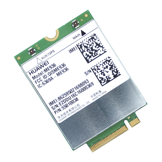
Page 69: Label
HUAWEI ME936 LTE M.2 Module Hardware Guide Mechanical Specifications Bottom View 6.3 Label Figure 6-2 Dimensions of front label (unit: mm) Huawei Proprietary and Confidential Issue 03 (2017-12-11) Copyright © Huawei Technologies Co., Ltd. -
Page 70: Packing System
ME936 package includes the blister tray, the blister tray cover, and the carton (with bottom and top clapboard). The blister tray of the ME936 module package is shown as in the following figure. There are 75 pcs modules for every tray, 6 pcs trays in one carton, and 450 pcs modules for every carton. -
Page 71: Installation
HUAWEI ME936 LTE M.2 Module Hardware Guide Installation Installation 7.1 About This Chapter This chapter describes the assembly of ME936, including: Connect ME936 to Board Antenna Plug 7.2 Connect ME936 to Board Figure 7-1 Install ME936 ME936 It refers to M.2 specification. -
Page 72: Thermal Management
HUAWEI ME936 LTE M.2 Module Hardware Guide Installation 7.3 Thermal Management Because ME936 is very small, the dissipating heat is very important to it. It has to take several means to ensure ME936 to meet the specification. The methods are described as follow: ... - Page 73 HUAWEI ME936 LTE M.2 Module Hardware Guide Installation Figure 7-3 Unmating the plug The extraction tool is recommended. Any attempt of unmating by pulling on the cable may result in damage and influence the mechanical/electrical performance. It is not recommended to apply any pull forces after the bending of the cable, as described in Figure 7-4 .
-
Page 74: Certifications
8.1 About This Chapter This chapter gives a general description of certifications of ME936. 8.2 Certifications Table 8-1 shows certifications the ME936 has been implemented. For more demands, please contact us for more details about this information. Table 8-1 Product Certifications... -
Page 75: Safety Information
HUAWEI ME936 LTE M.2 Module Hardware Guide Safety Information Safety Information Read the safety information carefully to ensure the correct and safe use of your wireless device. Applicable safety information must be observed. 9.1 Interference Power off your wireless device if using the device is prohibited. Do not use the wireless device when it causes danger or interference with electric devices. -
Page 76: Traffic Security
HUAWEI ME936 LTE M.2 Module Hardware Guide Safety Information Area indicated with the "Power off bi-direction wireless equipment" sign Area where you are generally suggested to stop the engine of a vehicle 9.4 Traffic Security Observe local laws and regulations while using the wireless device. To prevent accidents, do not use your wireless device while driving. -
Page 77: Laws And Regulations Observance
The following approvals and notices apply in specific regions as noted. 9.13.1 EU Regulatory Conformance Statement Hereby, Huawei Technologies Co., Ltd. declares that this device is in compliance with the essential requirements and other relevant provisions of Directive 2014/53/EU. Huawei Proprietary and Confidential Issue 03 (2017-12-11) Copyright ©... -
Page 78: Fcc Statement
Warning: Changes or modifications made to this equipment not expressly approved by HUAWEI may void the FCC authorization to operate this equipment. 9.13.3 IC Statement This device complies with CAN ICES-3 (B)/NMB-3(B). -
Page 79: Appendix A Circuit Of Typical Interface
HUAWEI ME936 LTE M.2 Module Hardware Guide Appendix A Circuit of Typical Interface Appendix A Circuit of Typical Interface Huawei Proprietary and Confidential Issue 03 (2017-12-11) Copyright © Huawei Technologies Co., Ltd. -
Page 80: Appendix B Acronyms And Abbreviations
HUAWEI ME936 LTE M.2 Module Hardware Guide Appendix B Acronyms and Abbreviations Appendix B Acronyms and Abbreviations Acronym or Abbreviation Expansion Application Process China Compulsory Certification European Conformity Coding Scheme Circuit Switched Data Direct Current Direct Memory Access External Bus Unit... - Page 81 HUAWEI ME936 LTE M.2 Module Hardware Guide Appendix B Acronyms and Abbreviations Acronym or Abbreviation Expansion HSUPA High Speed Up-link Packet Access International Standards Organization Liquid Crystal Polyester Low-Dropout Light-Emitting Diode New Name for NGFF Multi-chip Package NGFF Next Generation Form Factor...