Aspen Avionics Evolution EFD1000 PFD Pilot's Manual
Flight display
Hide thumbs
Also See for Evolution EFD1000 PFD:
- Pilot's manual (228 pages) ,
- Instruction manual (225 pages) ,
- Flight manual (41 pages)
Table of Contents
Advertisement
Quick Links
Advertisement
Table of Contents

Related Manuals for Aspen Avionics Evolution EFD1000 PFD


Summary of Contents for Aspen Avionics Evolution EFD1000 PFD
-
Page 3: Table Of Contents
Table of Contents Copyrights and Trademarks ............vii 2.2.1.2. Left Knob Functions ............2-5 SYNC Function ............2-6 2.2.1.3. LIMITED WARRANTY Aspen Avionics, Inc.......viii 2.2.1.4. Using the Knobs (Example) ........... 2-8 Conventions..................xi 2.2.2. Navigation Source Select Buttons ..........2-8 Covered Functionality .....................xi 2.2.2.1. - Page 4 Auto Course Select ..............2-31 4.1.2. Airspeed Indicator ..............4-4 4.1.2.1. Selected Airspeed .............. 4-6 Ground Track Indicator............2-32 4.1.2.2. Airspeed Display ..............4-6 2.3.3.2. Rate of Turn Indicator ............2-32 4.1.3. Altimeter ....................4-8 2.3.3.3. Vertical Speed Indicator (VSI) ........2-33 4.1.3.1. Barometric Pressure Adjustment (BARO) ....4-9 2.3.3.4.
- Page 5 4.3.9. Selected Heading and Heading Bug ........4-34 6.2. Pitot/Static System Blockage .................6-3 4.3.10. Aircraft Heading Display ............4-35 6.3. Loss of External Power ..................6-4 4.3.11. Rate of Turn Indicator ..............4-36 6.4. Power Override .......................6-4 4.3.12. Basemap Underlays ..............4-37 6.5. Abnormal Shutdown Procedure ..............6-6 4.3.12.1.
- Page 6 Table of Tasks Chapter 2 Set Barometric Units of Measure ................4-9 Set The Barometric Pressure .................4-10 Control Knob SYNC Function (Figure 2-3) ............2-6 Set Selected Altitude (Bug) ...................4-11 How to Set the Heading Bug (HDG) ..............2-8 Display/Hide Minimums ..................4-12 Access and Navigate The Menus...............2-15 Set Altitude Minimum .....................4-13 Edit Main Menu Items ....................2-16 Chapter 3...
- Page 7 Chapter 6 “NAV” Mode Operation – GPS Navigation ...........4-50 “APPR” Mode Operation – ILS Approach with Reset the AHRS ........................6-2 Vectors to Final ......................4-50 When Pitot or Static Line is Blocked ..............6-3 “APPR” Mode Operation – GPS or GPS/RNAV To Override the Automatic Power Configuration ........6-4 APV WAAS Approach ....................4-51 View External Power Status ..................6-5 GPS “APPR”...
- Page 8 Page vi EFD1000 PFD Pilot’s Guide A-01-184-00 REV B...
-
Page 9: Copyrights And Trademarks
Evolution™, EFD1000 Pro PFD™, EFD1000™, and the Aspen Avionics logo and operational details are subject to change without notice when are trademarks of Aspen Avionics, Inc. These trademarks may not be using an earlier or later software version. Please visit the Aspen used without the express permission of Aspen Avionics, Inc. -
Page 10: Limited Warranty Aspen Avionics, Inc
LIMITED WARRANTY Aspen Avionics, Inc. YOUR WARRANTY. Aspen Avionics, Inc. (“Aspen”) warrants to you, Maintain records accurately reflecting operating time of and the original purchaser, that its Products (if purchased from an authorized maintenance performed on the Product, dealer) will comply with applicable specifications (as set forth in the Furnish proof sufficient to establish that the item is a owner’s manual) in all material respects and will be free from material... - Page 11 Maintenance, repair, installation, handling, transportation, installed in accordance with all Aspen supplied technical information storage, operation (including, without limitation, operation and in accordance with all applicable FAA procedures and requirements. of the product’s software or host medium), or use which The warranty application form must note the repairman’s FAA certificate is improper or otherwise does not comply with Aspen’s number to be valid.
- Page 12 Aspen Customer Service at (505) 856-5034; by 12. DEALER WARRANTIES. Any express or implied warranty or remedy writing to Aspen Customer Service Department, Aspen Avionics, Inc., in addition to or different from those stated herein that is offered by a 5001 Indian School Road NE, Albuquerque, New Mexico, 87110;...
-
Page 13: Conventions
Conventions The following conventions, definitions, terminology, and colors are used in this manual and on the EFD1000 PFD. Covered Functionality This guide covers all the functionality available in the EFD1000 Pro PFD. Terminology Figure 1 shows a typical EFD1000 Pro PFD display. This guide uses the terminology listed in Table 1 when referring to specific parts of the EFD1000 Pro PFD. - Page 14 Term Example Attitude Display Data Bar Navigation Display Knobs Left (CRS) Knob, Right (HDG) Knob Buttons Left Button, CDI Button, Right Button Keys REV Key, RNG Key, MENU Key, Bezel Key(s) (1-5) Table 1 EFD1000 PFD Display, Knobs , Buttons, and Keys Figure 1 EFD1000 PFD Display, Knobs , Buttons, and Keys Page xii EFD1000 PFD Pilot’s Guide...
-
Page 15: Color Philosophy
Color Philosophy As the number of colors used on the NOTE display is limited, to ensure adequate Table 2 provides the operational philosophy of color usage on the EFD1000 PFD color differentiation under all lighting display. conditions, there are a few cases where a given color is used in a slightly COLOR PURPOSE... -
Page 16: Warnings, Cautions, And Notes
Warnings, Cautions, and Notes Where applicable warnings, cautions, and notes are given. Aspen Avionics uses the following icons and definitions (Table 3). Icon Definition Emphasizes a crucial operating or maintenance procedure, which, if not strictly observed, could result in injury to, or death of, personnel or long Warning term health hazards. -
Page 17: Example Graphics
While the EFD1000 is reasonably intuitive and easy to use, some familiarity with Electronic Flight Instrument Systems (EFIS) and Horizontal Situation Indicators (HSI) is required. Aspen Avionics strongly recommends that new users of the EFD1000 get some dual instruction from an experienced instrument CFI, and spend some time becoming familiar with the PFD in day VFR conditions with a safety pilot, before flying in actual instrument meteorological conditions (IMC). - Page 18 Page xvi EFD1000 PFD Pilot’s Guide A-01-184-00 REV B...
-
Page 19: Welcome & Introduction
Chapter 1 Welcome & Introduction Welcome to Aspen Avionics’ Evolution Flight Display (EFD) system, the most flexible, expandable, and upgradable Electronic Flight Instrument System (EFIS) available for General Aviation aircraft. Designed to replace traditional, mechanical primary flight instruments—in whole or in part, all at once, or in phases. - Page 20 The center of the EFD system is the EFD1000 Primary Flight Display (PFD), which replaces the traditional, mechanical Attitude Indicator (AI) and Directional Gyro (DG) or Horizontal Situation Indicator (HSI) (Figure 1-2). The PFD is available in three models—the Pilot, Pro and ATP—each with increasing levels of features and capabilities, and each lower model is upgradable through software to the more capable models.
- Page 21 “six-pack” replacement and gain even more capability and flexibility (Figure 1-4). When you are ready to upgrade, simply contact an Aspen Avionics Authorized Dealer for more information. Figure 1-4 Three-tube system: PFD & dual MFDs This Pilot’s Guide covers the EFD1000 Pro PFD models.
-
Page 22: System Overview
1.1. System Overview Pitot Static Existing Aircraft Existing Aircraft The EFD1000 Pro PFD system typically consists of Pitot Line Static Line four components: EFD1000 Display Unit Configuration Module (CM) Aircraft Power EFD1000 PFD Remote Remote Sensor Module (RSM) Sensor Module Analog Converter Unit (ACU) (Primary Flight Display) (RSM) -
Page 23: Efd1000 Display Unit
1.1.1. EFD1000 Display Unit Pitot & Static System Connections The EFD1000 system unit is a digital system that consists of a high resolution 6” diagonal color LCD display, user controls, photocell, and Micro SD data card slot. The three-inch diameter, four-inch deep can on the back of the display contains a non-removable electronics module which includes: •... -
Page 24: Configuration Module (Cm)
1.1.2. Configuration Module (CM) The Configuration Module contains an EEPROM device that retains system configuration and calibration data and provides two primary functions: • Retains aircraft-specific configuration information, calibration data, and user settings, allowing the PFD to be swapped for service purposes without re- entering or re-calibrating the installation. -
Page 25: Analog Converter Unit (Acu)
1.1.4. Analog Converter Unit (ACU) The Analog Converter Unit (ACU), included with most Pro PFD systems, enables the all-digital EFD1000 system to interface to analog avionics when required. The ACU concentrates multiple analog interfaces and converts them to the digital ARINC 429 buses supported by the PFD. - Page 26 Page 1-8 EFD1000 PFD Pilot’s Guide A-01-184-00 REV B...
-
Page 27: Controls And Display
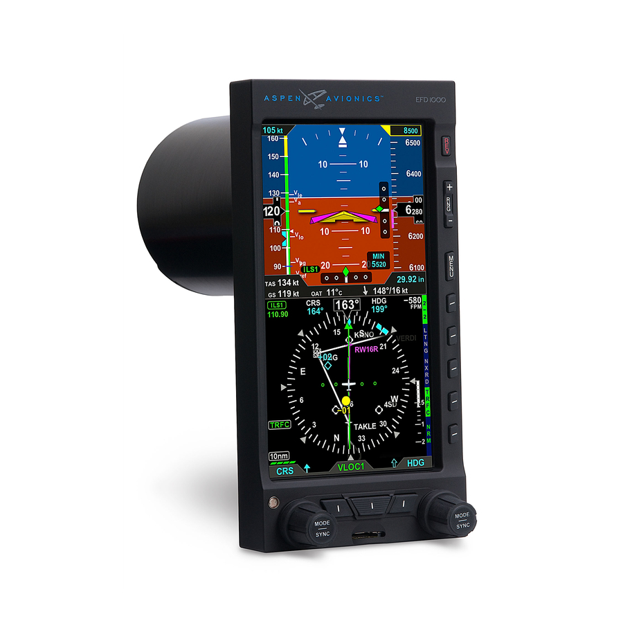
Chapter 2 Controls and Display The EFD1000 Pro PFD is a flat-panel LCD primary flight instrument that presents the pilot on a single display with all the information delivered by the traditional six-pack of mechanical instruments: Airspeed, Attitude, Altitude, Turn Coordinator, Heading Indicator (or HSI) and Vertical Speed Indicator (VSI). -
Page 28: Controls & Display Orientation
2.1. Controls & Display Orientation CONTROLS ATTITUDE DISPLAY Reversion and Power Control Attitude Display Range Control Aircraft Symbol Menu Control Single-Cue Flight Director (optional) TPS Hot Key - Tapes On/Off Roll Pointer MIN Hot Key - Minimums On/Off Slip/Skid Indicator 360/ARC Hot Key - HSI View Altitude Tape MAP Hot Key - Map Declutter Logic... - Page 29 DATABAR True Airspeed (TAS) Barometric Pressure Setting Field Wind Direction and Speed Wind Direction Arrow Outside Air Temperature (OAT) Ground Speed (GS) NAVIGATION DISPLAY Navigation Display Vertical Speed Tape Ownship Symbol Single-Line Bearing Pointer Single-Line Bearing Pointer Source Course Pointer Single-Line Source Info Block TO/FROM Indicator Rate of Turn Indicator...
-
Page 30: Controls
2.2. Controls The primary means for the pilot to control the EFD1000 are the two knobs and three buttons at the bottom of the display. The knobs control setting CRS and HDG, and additional bugs and altitude settings. The three buttons control selection of navigation sources for the CDI and bearing pointers. -
Page 31: Right Knob Functions
When the function you want to set is shown in magenta, dial the knob left or right to MIN will only be shown if the MIN set the desired value, or press and hold the knob to synchronize (SYNC) the setting. NOTE function is already active (the MIN Once set, you can either press the knob again to advance to the next function you’d like... -
Page 32: Sync Function
SYNC Function 2.2.1.3. Control Knob SYNC Function (Figure 2-3) Repeatedly press the control knob until the control knob label shows the value you want to set in magenta. Press and hold the control knob for approximately one (1) second to synchronize the setting according to the rules shown in Table 2-2. - Page 33 Left Knob SYNC Action Set to the current Indicated Airspeed. Set to the reciprocal value of the current VOR VOR navigation radial. The deviation bar centers with a “TO” indication. ILS navigation Current aircraft heading. Set to equal the bearing to the GPS active waypoint.
-
Page 34: Using The Knobs (Example)
2.2.1.4. Using the Knobs (Example) How to Set the Heading bug (HDG) From the Home state (at least 10 seconds since last using the Right Knob), press the right control knob once to select HDG for editing. The control knob label (HDG), the Heading Bug, and the Selected Heading field will all turn magenta (Figure 2-4). -
Page 35: Cdi Nav Source Control
2.2.2.1. CDI Nav Source Control The center button of the three buttons between the control knobs at the bottom of the EFD1000 Pro PFD (see Figure 2-7) is the CDI Nav Source Select Button. It selects which of the available navigation sources will couple to the CDI, which in turn couples to the autopilot (if available). -
Page 36: Bearing Pointer Nav Source Control
2.2.2.2. Bearing Pointer Nav Source Control The two outer buttons between the control knobs are the Bearing Pointer Nav Source Select Buttons (see Figure 2-7). The left-hand button controls BRG1 (the single-line bearing pointer) and the right-hand button controls BRG2 (the double-line bearing pointer), and each controls which nav source is coupled to that bearing pointer. -
Page 37: Hot Keys
2.2.3. Hot Keys The five keys along the lower right of the EFD1000 PFD function as either single-action Hot Keys for frequently used commands or as Menu selection keys when the Main Menu has been activated (Figure 2-9, page 2-12). Figure 2-8 Invalid Hot Key Legend Hot Key functions are accessible anytime, except when the Menu is active. - Page 38 HOT KEY DESCRIPTION OPTIONS Figure 2-9 Hot Keys Displays or hides air data tapes Tapes displayed (airspeed and altitude) (see Tapes hidden Section 4.1). Minimums displayed and Enables and displays, or disables alerter enabled and hides, Minimums Alerter (see Section 4.1.3.4). Minimums alerter disabled ARC Compass Mode Toggles between 360 and ARC...
-
Page 39: Menu Key
2.2.4. Menu Key The MENU Key is used to access the EFD1000 PFD’s Menu system for changing options, and also to change the EFD1000’s LCD brightness controls. 2.2.4.1. Using the Menus Figure 2-15 Press the MENU Key to activate the Menu system (Ref. 3). The current Menu Page Menu Navigation Mode Name displays in the lower center of the Navigation Display. - Page 40 Each Menu page displays up to five selectable options, each adjacent to one of the five Hot Keys (which double as Menu Select keys in the menu system). After navigating to the Menu Page containing the option you want to change, press the Menu Key adjacent to that option label, which initiates the menu’s Edit mode.
-
Page 41: Access And Navigate The Menus
The menu text will display in one of the four colors listed and described in Table 2-4. Figure 2-18 DISPLAY Menu Text - Editable DESCRIPTION DISPLAY TEXT WHITE Editable option See Figure 2-18 Figure 2-19 MAGENTA See Figure 2-19 Editable option enabled Menu Text - Enabled GREEN Non-Editable or “Status Only”... -
Page 42: Changing Lcd Display Brightness
Edit Main Menu Items Upon reaching the end of a list of Access the Main Menu. NOTE editable menu options, continued Navigate to the desired menu page. rotation of the knob shall result in Push the Menu Key of the desired option. The menu label turns magenta and the continuous “wrapping”... -
Page 43: Map Range Key
2.2.5. Map Range Key Pressing the Right Knob returns NOTE to navigation mode and allows When the MAP is enabled, the RNG (Range) key is used to zoom in or out in scale to selection of other menu options on display more or less of the map. -
Page 44: Display
2.3. Display The EFD1000 Pro PFD replaces the existing Attitude Indicator and HSI or DG in the center of the primary flight instrument cluster. Like the instruments it replaces, the top half presents an Attitude Display and the bottom half presents a Navigation Display (Figure 2-26). - Page 45 The EFD1000 PFD generally follows standard display conventions for Electronic Flight Instrument Systems (EFIS), so a pilot with some experience and familiarity with other EFIS PFDs will usually transition quickly to using the EFD1000. Pilots for whom the EFD1000 PFD is their first real exposure to EFIS and “glass cockpit” flying, however, should get some in-flight transition training from a certified instrument flight instructor (CFII) with EFIS experience.
-
Page 46: Attitude Display
2.3.1. Attitude Display The Attitude Display includes an Attitude Director Indicator (ADI) with single-cue Flight Director command V-bars (when connected to a compatible autopilot), an Airspeed tape, an Altimeter tape, an Altitude Alerter (with separate minimums alerting), and Instrument Approach indicators (Table 2-6 and Figure 2-27). For more details on each, see the Reference Guide, Chapter 4. - Page 47 ATTITUDE DISPLAY Attitude Display/Attitude Director Indicator (ADI) Aircraft Symbol Single-Cue Flight Director (optional) Roll Pointer Slip/Skid Indicator Altitude Tape Selected Altitude Field Altitude Alert Altitude Drum/Pointer Altitude Bug Decision Height Annunciation Selected Minimums Field Figure 2-27 Attitude Display Components MINIMUMS annunication LDI Navigation Source Indication Airspeed Indicator Tape Selected Airspeed Field...
-
Page 48: Attitude Director Indicator (Adi)
2.3.1.1. Attitude Director Indicator (ADI) The Attitude Director Indicator (ADI) features a conventional blue (sky) over brown (ground) background, with a white horizon line dividing the two areas. A triangular aircraft reference symbol (Ref. 17) is in a fixed position, and shows aircraft attitude Figure 2-28 relative to the horizon. -
Page 49: Airspeed Tape And Bug
2.3.1.2. Airspeed Tape and Bug Airspeed is indicated by a moving airspeed tape against a fixed position airspeed pointer, shown on the left-hand side of the Attitude Display (Figure 2-30). A digital, rolling drum readout indicating airspeed values to the closest one knot or mile per hour is provided adjacent to the fixed pointer. -
Page 50: Altitude Tape And Alerter
2.3.1.3. Altitude Tape and Alerter Altitude is indicated by a moving altitude tape against a fixed position altitude pointer (Figure 2-2, No. 24), shown on the right-hand side of the Attitude Display (Figure 2-31). A digital, rolling drum readout indicating altitude values to the closest 20 feet is provided adjacent to the fixed pointer. -
Page 51: Instrument Approach Indicators
2.3.1.4. Instrument Approach Indicators Additional indicators are shown or available on the Attitude Display when flying certain types of instrument approaches. These enable the pilot to maintain a tighter instrument scan on the ADI, reducing workload and improving safety (Figure 2-32). A Lateral Deviation Indicator (LDI, (Figure 2-2, No. -
Page 52: Data Bar
2.3.2. Data Bar The Data Bar visually separates the upper and lower halves of the PFD display. When available, True Airspeed (TAS), GPS Ground Speed (GS), Outside Air Temperature (OAT), NOTE When the winds aloft are less than Wind Vector arrow, Wind Direction and Speed, and Barometric Pressure Setting data are 10 knots, the wind data is dashed. -
Page 53: Navigation Display
2.3.3. Navigation Display The lower half of the EFD1000 PFD is the Navigation Display, which shows a wide range of navigation information and flight data, including (Figure 2-35): • Horizontal Situation Indicator (HSI), with Course Pointer and Deviation Indicator (CDI), and Heading Bug, offering both 360º and ARC mode views. •... - Page 54 NAVIGATION DISPLAY Navigation Display Vertical Speed Tape Ownship Symbol Single-Line Bearing Pointer Course Pointer Single-Line Bearing Pointer Source TO/FROM Indicator Single-Line Source Info Block Rate of Turn Indicator Double-Line Bearing Pointer Track Marker Double-Line Bearing Pointer Source Magnetic Heading Double-Line Source Info Block Selected Course (CRS) Field CDI Navigation Source Selected Heading Field...
-
Page 55: Horizontal Situation Indicator (Hsi)
2.3.3.1. Horizontal Situation Indicator (HSI) The traditional HSI is an instrument that combines a slaved magnetic Heading Indicator overlaid with a rotating Course Pointer and Deviation Indicator (CDI). This combination has also been called a pictorial navigation indicator, because it helps the pilot better visualize the aircraft position relative to its desired course. -
Page 56: Navigation Setting Information
Navigation Setting Information Regardless of compass mode setting, the current magnetic heading is always shown at the top center of the Navigation Display (Figure 2-2, No. 48 and Figure 2-37). The current setting of the HDG Bug (Figure 2-2, No. 50) is always shown to the right of the Figure 2-37 ship’s heading, even if the HDG Bug itself may not be visible in ARC mode. -
Page 57: Deviation Off Scale Indication
resembling that used in contemporary GPS navigation displays. ARC CDI mode leaves more open space for map presentation. A TO indication is shown to the left of the LDI, Figure 2-40 while a FROM indication is shown to its right. Off Scale ARC CDI Deviation Off Scale Indication Whenever the course deviation exceeds the maximum displayable range of 2.5 dots,... -
Page 58: Ground Track Indicator
Ground Track Indicator Whenever the EFD1000 is connected to a compatible GPS, a Ground Track Indicator is displayed. Ground Track is shown as a blue diamond rendered on the compass scale Figure 2-43 at the value that corresponds to the current aircraft track (Figure 2-2, No. 47 and Current Heading Figure 2-43). -
Page 59: Vertical Speed Indicator (Vsi)
2.3.3.3. Vertical Speed Indicator (VSI) Figure 2-46 Whenever the vertical speed exceeds +/- 100 FPM, the vertical speed is indicated VSI Tape Capped, Digital Value by presenting a rising/sinking white vertical tape and associated scale markers Showing 2,100 FPM Climb immediately to the right of the compass rose (Figure 2-2, No. -
Page 60: Situational Awareness Map Display
information about the source of the bearing pointer data. Information that can be displayed includes distance to station (if coupled to a GPS waypoint) and either the station identifier or the tuned frequency for a VLOC radio. This information is only presented when it is reported to the EFD1000 by the connected equipment, and thus is not available in all installations. - Page 61 off the base map display. Each successive press of the MAP hot key selects the next feature level or OFF. The map display range is controlled by the Range Control toggle button (Figure 2-2, Ref. 2), enabling the pilot to zoom in or out on the map. Automatic declutter logic changes the map features display depending on the selected map range.
- Page 62 Page 2-36 EFD1000 PFD Pilot’s Guide A-01-184-00 REV B...
-
Page 63: Flying The Efd1000 Pro Pfd
Chapter 3 Flying the EFD1000 Pro PFD This chapter provides an overview of flying the EFD1000 Pro PFD on an IFR cross-country flight, explaining how to access and change the necessary settings of the EFD1000 PFD (Table 3-1). Refer to Chapter 4 for detailed step-by-step instructions for all EFD1000 PFD functionality. - Page 64 FEATURE SETTING FEATURE SETTING Selected GPS Steering Set as desired Enable/Disable Altitude (GPSS) Hot Key Bearing Basemap Set as desired Pointers Nav Select as desired Range Keys Source Barometric CDI Navigation Pressure Check and set Select as desired Source Setting Heading Course Pointer Set as desired...
-
Page 65: Quick Controls Overview
3.1. Quick Controls Overview Chapter 2 explains the EFD1000 controls in detail. The following is a quick summary: Control Knobs (see 2.2.1 for detail) • The Left and Right control knobs each has a Home state, to which it returns after 10 seconds of inactivity. -
Page 66: Example Flight Scenario
Navigation Source buttons (see 2.2.2 for detail) • Three buttons at the bottom of the display couple the available navigation sources to the CDI and/or the bearing pointers. Figure 2-2, Ref. 11) selects the nav source to couple to • The center button ( the CDI and to drive the autopilot (if installed). -
Page 67: Pre-Departure
default settings. The Garmin 430Ws are configured with ILS CDI Capture set to AUTO, meaning that when an ILS approach is loaded and active in the GPS, and the aircraft is established inbound to the FAF, the 430W will automatically switch its CDI output from GPS to the VHF localizer frequency. - Page 68 Start-up times for the EFD1000 are highly dependent on aircraft NOTE temperature. In extremely cold weather, when the aircraft has gotten cold soaked overnight, it may take several minutes (usually no more than five) for the PFD to be fully operational. On the second or third flight of the day, and/or on very hot days, the PFD may come up within 30 seconds or less.
-
Page 69: Set The Barometric Pressure
First set the standby altimeter to 30.15, and then set the EFD1000 PFD baro setting. Set the barometric Pressure Press the Right Knob until BARO displays above the knob and the Barometric Pressure field is enabled for editing, both rendered in magenta (Figure 3-7). From the Home state, press the Right Knob 3 times to enable setting baro pressure. -
Page 70: Set The Heading Bug
Next, since we’ll be departing from Runway 8, we set our Heading Bug to runway heading, 080°. Set the Heading bug Press the Right Knob until HDG displays above the knob and the HDG field is enabled for editing, both rendered in magenta (Figure 3-9). The Heading Bug will also be rendered in magenta, and a dashed magenta line will extend from the ownship symbol to the Heading Bug to make it easier to see the bug position. -
Page 71: Select The Cdi Navigation Source
On the EFD1000, use the CDI Source Select button to select GPS1. Because we have enabled Auto Course Select, the Course Pointer automatically slews to 261º (the initial course from the airport to the first fix on the LARGO2 departure, ABQ VOR). Select The CDI Navigation Source •... -
Page 72: Select Map Level Of Detail
For even better situational awareness, we choose to display the basemap of our flight plan legs and waypoints. We press the MAP Hot Key to bring up the base map. We use the Range Control buttons to select the 20 NM. range, which will give a good perspective for intercepting our course to ZUN. -
Page 73: Change The Basemap Range
Change The basemap Range • Press the Range key ( Figure 3-15) UP (+) to increase the range, or DOWN (-) to decrease the range, until the desired range is reached (Figures 3-16 and 3-17). Figure 3-15 Range Key Figure 3-17 Current Range 10NM from Ownship to Edge of Compass Ownship... -
Page 74: Set The Altitude Alerter
Next, we set our assigned initial altitude of 7,000 feet into the Altitude Alerter. We press the Right Control Knob twice, changing the legend above the knob to ALT in magenta. Then we turn the right knob to set 7,000 into the Selected Altitude Field. This will help us capture and maintain our assigned altitude. -
Page 75: Set The Airspeed Bug
Our normal climb speed is 120 KIAS, so we choose to set the airspeed bug as a reminder. To do so, we press the Left Control Knob twice, until it shows IAS in magenta above the knob. We turn the knob until 120 shows in the Selected Airspeed Field. Set the Airspeed bug Press the Left Knob until IAS displays above the Left Knob and the Selected Figure 3-22... -
Page 76: Departure
We plan to hand-fly the plane until reaching our final en route altitude of 10,000 feet. But we like the help the Flight Director gives us (Figure 3-24). So, as part of our Before Takeoff set-up, we press the FD button on the autopilot mode selector, and the magenta V-bars display on the EFD1000. - Page 77 Soon we hear a one-second tone and see the yellow flag come on next to our Selected Altitude at the top of the EFD1000 airspeed tape (Figure 3-25). This means we are 15 seconds away from reaching our assigned altitude. We begin to shallow our climb, and level off at 7,000 feet, engaging ALT hold on the AP/FD mode selector.
-
Page 78: En Route
flag flashing, our altitude at 10,200 and climbing, and our Flight Director V-bars commanding pitch down. We quickly stop the climb, correct back down to our assigned altitude of 10,000 and engage the autopilot before calling to check in with Center. -
Page 79: Arrival And Approach To Landing
Now that we’re established at our final cruise altitude and in the en route phase of our Each HSI view (360 and ARC) retains flight, we’ll switch to the ARC mode of the HSI, to maximize a forward view. NOTE its own Range and Map Feature Level Press the 360 Hot Key, and observe the HSI changes to its ARC view, and the settings when switching between the... - Page 80 We load the KRNO ILS16R approach into the GPS, selecting TAKLE as our IAF. The ILS frequency (110.9) is placed in the standby window of the 430W. Briefing the approach, we note our Decision Altitude (DA) is 5,515 feet. We set our approach MINIMUMS on the EFD1000 to 5,520 feet (MIN are set in increments of 10 feet, so we round up).
- Page 81 We activate the approach on the GPS, and move the ILS frequency into the active window. GPSS continues to steer the plane to the initial approach fix, TAKLE, and, crossing TAKLE, turns us outbound on a 344º course for the procedure turn (Figure 3-34). We see the procedure turn drawn on our base map ahead of us, and watch it turn magenta as GPSS turns and flies the procedure turn for us, with no further pilot action required.
-
Page 82: Conclusion
When the GS is full-scale deflection above us, the GS indicator on the VDI will show as a hollow diamond at the top of the scale (Figure 3-35). When the GS comes alive, the indicator will change to a solid green diamond and begin to move down the scale. Just before intercepting the GS, drop the gear, and check for three green lights. -
Page 83: Chapter 4 Reference Guide
Chapter 4 Reference Guide The EFD1000 PFD is a panel-mounted Electronic Flight Instrument System (EFIS) that presents the pilot with displays of attitude, altitude, indicated airspeed, heading, rate of turn, slip/skid, and navigation course deviation information. The system also displays supplemental flight data such as winds, TAS, OAT, etc., moving maps, pilot-selectable indices (“bugs”), and various annunciations to increase situational awareness and enhance flight safety. -
Page 84: Attitude Display
4.1. Attitude Display 4.1.1. Attitude Indicator The Attitude Indicator consists of an aircraft reference symbol on a blue (sky) and brown (ground) background. The white horizon line separates the sky from the ground and extends to the edge of the display. The Roll Scale curves over the top of the Attitude Indicator while the Pitch Scale extends vertically in the middle. -
Page 85: Roll Scale
4.1.1.1. Roll Scale The Roll Scale is displayed at the top of the Attitude Indicator and is comprised of a moving scale set against a fixed, white, triangle roll pointer. Tick marks are displayed at 0º, 10º, 20º, 30º, 45º and 60º of roll. The 45º marks are triangles. 4.1.1.2. -
Page 86: Degraded Attitude Heading Reference System (Ahrs) Performance
4.1.1.5. Degraded Attitude Heading Reference System (AHRS) Performance See Chapter 6, Emergency Procedures. 4.1.2. Airspeed Indicator The airspeed indicator is comprised of a moving tape, airspeed bug, and numerical airspeed value (drum). Textual V-speeds, color Speed Bands, and Speed Markers are also rendered on the moving tape (Figure 4-5). - Page 87 Indicated airspeed is displayed in knots or miles per hour, set at installation, with tick marks rendered on the Airspeed tape every ten (10) units. Speed Bands and Speed Markers are configured during installation and cannot be changed or removed by the pilot.
-
Page 88: Selected Airspeed
4.1.2.1. Selected Airspeed The Selected Airspeed value (bug) is rendered on the Airspeed Tape numerically and graphically. The numerical value is shown at the top of the Airspeed Tape. The bug is displayed adjacent to the Airspeed Tape when the Selected Airspeed value is within the visible range of the tape. -
Page 89: Hide/Display Airspeed Tape
Hide/Display Airspeed Tape • Press the TPS Hot Key to alternately hide or display the Airspeed and Altitude Tape (Figures 4-9 and 4-10). Figure 4-10 Airspeed Tape Disabled NOTE Both the Airspeed and Altitude tape are affected by this action. NOTE When the Airspeed tape is disabled, the numerical display of the... -
Page 90: Altimeter
4.1.3. Altimeter The altimeter is comprised of an altitude bug, a numerical altitude value (drum), a moving tape, a MINIMUMS annunciation and adjustable value, a Decision Height (DH) alert, and a visual/aural altitude alerter (Figure 4-11). Altitude Alerter MINIMUMS Adjustment Selected Altitude MINIMUMS Alert Numerical Altitude Value... -
Page 91: Barometric Pressure Adjustment (Baro)
4.1.3.1. Barometric Pressure Adjustment (BARO) Barometric pressure adjustment may be made in either inches of mercury (in) (Figure 4-13) or millibars (mB) (Figure 4-14), as configured by the pilot. The adjustment range is 28.10 – 30.99 inches Hg or 946 – 1049 mB. The Barometric pressure default value and units of measure is 29.92 and inches Hg, or as previously set. -
Page 92: Set The Barometric Pressure
Set The barometric Pressure Adjust the EFD1000’ s barometric NOTE Press the Right Knob until BARO displays above the Right Knob and the pressure whenever the mechanical barometric pressure field is enabled for editing, both rendered in magenta altimeter’ s barometric pressure is (Figure 4-18). -
Page 93: Selected Altitude
4.1.3.2. Selected Altitude The Selected Altitude value is displayed at the top of the Altitude Tape. The Selected Figure 4-20 Altitude range is 100 to 51,000 feet, in 20 foot increments. The default value for the Altitude Alert Selected Altitude value is 100 feet, or the previously set value. Additionally, an altitude bug is displayed adjacent to the Altitude Tape and at the selected altitude, when within the visible range of the current altitude. -
Page 94: Minimums Alert
4.1.3.4. MINIMUMS Alert Pressing the MIN Hot Key turns on NOTE The EFD1000 PFD provides an adjustable MINIMUMS field to enhance situational the MINIMUMS display and enables awareness during instrument approaches. Once the MIN data field value is set to a the MIN data field for editing. -
Page 95: Decision Height Annunciation
The range for the MIN data field is 0 – 15,000 feet, in increments of 10 feet. Synchronizing sets the MIN data field value to the current altitude (Section 2.2.1.3). The default value is 100 feet or the previously set value. Set Altitude Minimum Press the Right Knob until MIN displays above the Right Knob and the MINIMUMS field is enabled for editing, both rendered in magenta... -
Page 96: Altitude Display
4.1.3.6. Altitude Display A typical installation sets the tapes NOTE display to UNLOCKED, allowing the The altitude tape can be turned off, at the pilot’s discretion, to facilitate screen declutter. pilot to display or hide the Airspeed Hide/Display Altitude Tape and Altitude tapes as desired. -
Page 97: Data Bar
4.2. Data Bar The Data Bar presents True Airspeed (TAS), GPS Ground Speed (GS), Outside Air Temperature (OAT), Wind Direction, Wind Speed, and Barometric Pressure Setting as shown in Figure 4-30. The data bar is always present on the display. Invalid or out-of-range Data Bar values are dashed. -
Page 98: True Airspeed
4.2.1. True Airspeed The True Airspeed (TAS) is displayed on the upper left of the Data Bar with a value range of 20 – 999 knots or mph, using the same unit of measurement as the Airspeed Indicator. The TAS is a correction of the IAS for nonstandard pressure and temperature. 4.2.2. -
Page 99: Wind Speed, Direction, And Arrow
4.2.4. Wind Speed, Direction, and Arrow NOTE The wind computations require a GPS- The Wind Speed, Direction, and Direction Arrow are displayed in the lower right portion supplied ground track and ground of the Data Bar. If the data are out of range or invalid, the values are dashed and the speed to compute the wind direction wind arrow is removed. -
Page 100: Navigation Display
4.3. Navigation Display The Horizontal Situation Indicator (HSI), on the Navigation Display of the EFD1000 PFD, The shape, location, and size of the combines a Direction Indicator with a Course Deviation Indicator (CDI) (Figure 4-32). NOTE course pointer and deviation scale and indicator depend on the compass The Direction Indicator consists of a compass, numerical direction indication, heading mode selected. -
Page 101: Compass
All instrument values on the HSI are displayed in degrees. The value range is from 001° - 360°, always displayed in three digits, and utilizing leading zeros when applicable. Magnetic North is numerically represented as 360°. 4.3.1. Compass The EFD1000 PFD offers three compass modes: 360°, ARC HSI, and ARC CDI. The default compass mode is 360°. -
Page 102: Select Arc Cdi/Hsi Compass Mode
The ARC CDI mode uses a fixed, non-rotating CDI indicator, resembling a contemporary GPS navigation deviation display. The ARC CDI Compass mode is intended to maximize the lower display area for basemap and flight plan data (Figure 4-35). Select ARC CDI/HSI Compass Mode Push the MENU key. -
Page 103: Select Compass Type
Select Compass Type • Push the 360/ARC Hot Key (Figure 4-39) to alternately select either the 360° or ARC Compass. The Navigation Display changes and the Hot Key label reflects the currently selected compass type (Figures 4-40 and 4-41). Figure 4-40 ARC Compass Mode Figure 4-39 Figure 4-41... -
Page 104: Course Pointer
4.3.2. Course Pointer For all compass modes, the arrowhead of the course pointer aligns with the corresponding value on the compass scale regardless of the aircraft heading. The ARC Compass HSI and CDI course pointers are different and described in Table 4-1. COMPASS DESCRIPTION ARC HSI... -
Page 105: To/From Indicator
4.3.3. TO/FROM Indicator Each of the compass modes has a TO/FROM indicator. The TO/FROM indicator shows whether the aircraft is heading toward a waypoint or radio navaid, or from a waypoint or radio navaid. For each compass mode, the TO/FROM indication is slightly different, as described in Table 4-2. -
Page 106: Course Deviation Indicator And Scale
4.3.4. Course Deviation Indicator and Scale Selected course deviation is depicted by a Course Deviation Indicator and Scale. Deviation is indicated by positioning the Course Deviation Indicator on the Scale corresponding to the lateral deviation value. The 360° and ARC HSI compass modes display the CDI as a green line centered on the display and parallel with the course indicator. -
Page 107: Cdi Navigation Source
4.3.5. CDI Navigation Source For integrated systems, the CDI NOTE navigation source label indicates the When the EFD1000 PFD powers up, the default CDI Navigation Source is the last current operating mode (“GPS” or selected or the first configured navigation source, if no previous selection was made. “VLOC”) of the GPS/VHF NAV system. -
Page 108: Select The Cdi Navigation Source
Select The CDI Navigation Source • Press the CDI Navigation Source Select button until the desired navigation source is displayed above the button (e.g., GPS1, GPS2, VLOC1, VLOC2) (Figure 4-56). CDI Source Select Button CDI Source Label CDI Source Information Block Figure 4-56 Whenever the CDI navigation source navigation data is valid, a navigation information Navigation Source Information Block... - Page 109 Waypoint identifier or tuned frequency (when available) Bearing (in degrees)/Distance (in Nautical Miles) to waypoint or navaid (when available) Estimated Time En route (Hours:Minutes) Figure 4-59 When both the navigation source identifier and the tuned frequency of the associated Invalid CDI Navigation VHF NAV radio are available, only the source identifier information shall be displayed on Source Label the second line of the information block.
-
Page 110: Auto Course
4.3.6. Auto Course The pilot can either use the AUTOCRS or manually set a CRS value. By default, AUTOCRS is enabled. When the selected CDI navigation source is a connected GPS receiver, and AUTOCRS is enabled, CRS is not adjustable (current course value is automatically slewed and controlled by the desired track from the GPS). -
Page 111: Disable Autocrs
Disable AUTOCRS Push the MENU Key. The Menu displays on the Navigation Display. Rotate the Right Knob counterclockwise until Page 1 of the Menu displays (Figure 4-65). Push the AUTOCRS Menu Key (Key 3). The menu label turns magenta and the EDIT VALUE label displays above the Right Knob (Figure 4-66). -
Page 112: Cdi Selected Course
4.3.7. CDI Selected Course When the CDI source changes from a GPS source with AUTOCRS to another CDI source, the CRS value reverts to the last set value. When the CDI source is set to a VHF receiver operating in the VOR or Localizer modes, editing the CRS value adjusts the current selected CRS value. -
Page 113: Bearing Pointer Source Selection
4.3.8. Bearing Pointer Source Selection When the 360° Compass mode is selected, single- and double-line bearing pointers are available (Figure 4-69). The bearing pointers are independent of the CDI and provide supplemental navigation information by pointing to active GPS waypoints or navaids. By default, the bearing pointers are off and not displayed. - Page 114 The bearing pointers indicate only the bearing information provided by their selected A VOR that is tuned to a localizer navigation sources. They resemble and perform like traditional Radio Magnetic NOTE frequency shall be considered an Indicator (RMI) needles. Each bearing pointer’s head and tail is aligned with the invalid bearing pointer source since corresponding bearing/radial value on the compass.
-
Page 115: Select The Single-Line Bearing Pointer Source
Select The Single-Line bearing Pointer Source • Press the Single-Line Bearing Pointer button (lower left button, Figure 4-73) until the desired navigation source displays above the Single-Line Bearing Pointer button. Select The Double-Line bearing Pointer Source • Press the Double-Line Bearing Pointer button (lower right button, Figure 4-74) until the desired navigation source displays above the Double- Figure 4-73 173 Single-Line Bearing Pointer and Button... -
Page 116: Selected Heading And Heading Bug
4.3.9. Selected Heading and Heading Bug The EFD1000 PFD offers a pilot-selectable heading bug. The heading bug symbol is positioned on the compass scale according to the heading bug value (HDG) selected by the pilot (Figure 4-75). When the selected HDG value is outside the visible compass scale range, in ARC Compass mode, only a portion of the heading bug is shown at the edge of the compass arc, closest to the HDG value (Figure 4-76). -
Page 117: Aircraft Heading Display
When selected for editing, the heading bug and the HDG value are shown in magenta. Additionally, a dashed magenta line extends from the ownship symbol to the heading bug, corresponding to the selected HDG value. When heading bug is SYNCed, the HDG value is set to the current heading. -
Page 118: Rate Of Turn Indicator
4.3.11. Rate of Turn Indicator The Rate of Turn Indicator consists of a curved white line originating from the corresponding side of the aircraft heading (i.e., a left turn indication starts on the left side of the index mark), and extends in the direction of the turn along the outer radius Figure 4-80 of the compass scale. -
Page 119: Basemap Underlays
4.3.12. Basemap Underlays The basemap is comprised of symbols depicting the location of flight plan waypoints and legs, airports, VORs, DMEs, NDBs, and intersections. The map is always oriented with magnetic heading up and centered so that the current aircraft position coincides with the aircraft ownship symbol. -
Page 120: Basemap Display And Range
4.3.12.1. Basemap Display and Range If connected to a GPS system that does NOTE To turn the basemap on or off, the pilot selects one of the feature display levels as not provide compatible Basemap described in Section 5.2. The default feature display level is HIGH. The map range data, then only OFF and FP ONLY displays so that the outside radius of the compass represents 2.5, 5, 10, 15, 20, 30, 40, display levels are available. -
Page 121: Set Basemap Range
Set basemap Range The map range increases or decreases NOTE Figure 4-86) until the • Press the Range Up (+) or the Range Down (-) Key ( one increment each time the +/- desired range is displayed (Figure 4-87). button is pressed. To continuously increase/decrease the range, press and hold either button for more than a half second. -
Page 122: Flight Plan
4.3.12.2. Flight Plan When a flight plan is provided by a configured GPS, the basemap shows flight plan waypoints and legs. The active leg and waypoint and associated identifier are displayed in magenta. Other waypoints and legs are white. Straight and curved flight plan details are rotated within the basemap display to maintain their correct compass orientations Figure 4-88 GPS1 Failure, Reversionary Navigation at all times. -
Page 123: Track Indicator
4.3.13. Track Indicator When configured with a GPS that provides ground track data, a blue track indicator diamond is displayed on the compass scale to indicate the aircraft’s ground track. Figure 4-91 This indicator may be used to compensate for wind drift during flight (Figures 4-91 ARC Compass Mode, Ground and 4-92). -
Page 124: Lateral Deviation Indicator
4.4.1. Lateral Deviation Indicator The LDI automatically displays when: • The active navigation source is a GPS radio and the GPS is in approach Figure 4-94 mode and valid. Lateral Deviation Indicator Exceed • The active navigation source is a VHF navigation radio and a valid LOC, LOC(BC), or ILS signal is received. -
Page 125: Vertical Deviation Indicator
4.4.2. Vertical Deviation Indicator The Vertical Deviation Indicator (VDI) is enabled on the attitude indicator when the active navigation source is a VHF navigation radio, the ILS mode is active, and a valid localizer signal is being received. The VDI is also displayed for a GPS, supplying valid vertical deviation data, when in the approach mode. - Page 126 The VSI tape is nonlinear, giving more display area to the 0 to ± 1,000 FPM range than to the ±1,000 to ±2,000 FPM range. Tick marks are presented only in the direction of the climb or descent to provide visual cues for trends. The VSI numerical value, tape, and scale markers are only shown if the aircraft is climbing or descending more than ±100 FPM.
-
Page 127: Autopilot Integration
4.6. Autopilot Integration NOTE Refer to the autopilot AFMS for The EFD1000 can connect with many different legacy autopilot systems that are information on the operation of the typically found in general aviation aircraft. The EFD1000 emulates the HSI and/or autopilot or flight director. -
Page 128: Gps Steering (Gpss)
4.6.1. GPS Steering (GPSS) Refer to the Aircraft Flight Manual NOTE Supplement for your GPS system for GPS Steering represents a modernized approach to flying between flight plan information about GPSS steering waypoints, and offers many advantages of over traditional methods of flying direct commands that may be output by course lines between waypoints. -
Page 129: Flight Director
on the EFD1000 and the Heading mode of the autopilot, the autopilot is able to fly GPS Steering commands. When GPSS is not selected, the autopilot will follow the heading bug value manually set by the pilot. If the connected GPS system does not provide the required roll steering command, the GPSS legend adjacent to the GPSS Hot Key will be rendered in gray and it will not be possible to enable GPSS operation via the Hot Key. -
Page 130: Typical Autopilot Operations
4.6.3. Typical Autopilot Operations When GPSS is enabled on the NOTE EFD1000, the HSI heading bug is not Whenever the EFD1000 installed configuration includes connections to GPS, VLOC and coupled to the autopilot. To connect autopilot systems, the EFD1000 acts as a conduit of data between the navigation radios the heading bug to the autopilot, and the autopilot system. -
Page 131: Hdg" Mode Operation - Heading Bug Steering
“HDG” Mode Operation – Heading bug Steering Set the heading bug on the EFD1000 to the desired heading (Section 4.3.9). Verify that GPSS is not selected (GPSS Legend on Hot Keys shown in GRAY). Select the autopilot’s HDG mode. Engage the autopilot. Verify that the autopilot turns the aircraft to the selected heading. -
Page 132: Nav" Mode Operation - Gps Navigation
“NAV” Mode Operation – GPS Navigation With a valid flight plan programmed and active in the GPS, use the CDI Nav Source Select button to couple the GPS to the CDI (Section 4.3.5). If Auto Course Select is disabled, set the Course Pointer to the desired course (4.3.7), or enable Auto Course Select (Section 4.3.6). -
Page 133: Appr" Mode Operation - Gps Or Gps/Rnav Apv Waas Approach
“APPR” Mode Operation – GPS or GPS/RNAV APV WAAS Approach WAAS GPS systems can provide vertical NOTE With a valid GPS approach programmed in the GPS, use the CDI Nav Source guidance on several types of GPS/RNAV Select button to couple the GPS to the CDI (Section 4.3.5). instrument approaches. -
Page 134: Gps "Appr" Mode Operation - Waas Gps Underlay To Ils Approach Using Pilot Nav
GPS “APPR” Mode Operation – WAAS GPS Underlay to ILS Approach The EFD1000 enables GPS APV Using Pilot Nav NOTE approaches (Approaches with Vertical With a valid ILS approach loaded and active in the GPS, use the CDI Nav Guidance) by providing the autopilot Source Select button to couple the GPS to the CDI (Section 4.3.9). -
Page 135: Gps "Appr" Mode Operation - Waas Gps Underlay To Ils Approach With Atc Vectors To Final
GPS “APPR” Mode Operation – WAAS GPS Underlay to ILS Approach With ATC Vectors to Final With a valid ILS approach loaded and active in the GPS, use the CDI Nav Source Select button to couple the GPS to the CDI (Section 4.3.5). Verify that the correct ILS frequency is tuned. - Page 136 Page 4-54 EFD1000 PFD Pilot’s Guide A-01-184-00 REV B...
-
Page 137: Customizing The Efd1000 Pfd
Chapter 5 Customizing the EFD1000 PFD 5.1. Using the Menu System There are seven (7) Menu pages, each with up to five (5) menu options. The following tables and figures provide a brief overview of each menu page. KEY DESCRIPTION OPTIONS Barometer Setting Units IN or mB... - Page 138 KEY DESCRIPTION OPTIONS 360° Flight Plan OFF, AUTO or ON 360° Airports OFF, AUTO or ON 360° NDB OFF, AUTO or ON 360° VORs (High, Low and Terminal) OFF, AUTO or ON Figure 5-2 Menu, Page 2 360° Intersections OFF, AUTO or ON Table 5-2 Menu - 360°...
- Page 139 KEY DESCRIPTION OPTIONS ARC Flight Plan OFF, AUTO or ON ARC Airports OFF, AUTO or ON ARC NDB OFF, AUTO or ON ARC VORs (High, Low and Terminal) OFF, AUTO or ON Figure 5-3 Menu, Page 3 ARC Intersections OFF, AUTO or ON Table 5-3 Menu - ARC MAP SETTINGS, Page 3 of 7 A-01-184-00 REV B Page 5-3...
- Page 140 KEY DESCRIPTION OPTIONS For external/battery power control, NOTE the legend of the current power 0 to 450 or LOCKED source is shown in green; pressing the associated menu key will perform no action. The legend of an available 0 to 450 or LOCKED power source is shown in white, and pressing the associated menu key changes input power to that power...
- Page 141 KEY DESCRIPTION OPTIONS Operating from or Switch to Battery Power. Green when current state Status or (Pushing key performs no action) White if selection is possible Action Operating from or Switch to External Power. Green when current state Status or (Pushing key performs no action) White if selection is possible Action Shut down...
-
Page 142: Customizing The Map
5.2. Customizing the Map The pilot can customize the display setting for the map symbol levels HIGH, MEDIUM, and LOW; choosing from: Display symbol is always on. The selected display level and range, as described in Table 5-8, determine AUTO which map symbols are displayed. - Page 143 Table 5-8 LEVEL DISPLAY DESCRIPTION Map Display Levels No symbols, legs, or waypoints - regardless of selected range - are Fixed displayed. When selected, the map symbol level and range icons Figure 5-12 No Map Figure 5-17 display for two seconds and then are removed from view. The MAP Basemap “OFF”...
-
Page 144: Configuring V-Speeds
5.3. Configuring V-speeds V-speeds are used to designate different operating speeds of the aircraft and are defined in Table 5-9. V-SPEED DEFINITION PRE-SET ADJUSTABLE PRE-SET BANDS TEXT LABELS MARKERS Never exceed x (Red Line) Maximum structural cruising rate Maximum full flap extension speed Full flap stall Maneuvering at maximum... - Page 145 V-SPEED DEFINITION PRE-SET ADJUSTABLE PRE-SET MARKERS BANDS TEXT LABELS Retract maximum landing gear operation speed (Multi-engine planes) Single engine minimum x (Red Line) control (Multi-engine (Multi-engine planes) planes) Single Vyse Single engine minimum engine best rate control of climb Initial flap extension Setting the value of the white triangle, NOTE Vyse, and Vmc markers to zero (0)
- Page 146 The EFD1000 PFD uses colored speed bands, colored speed markers, and textual labels to help the pilot recall V-speed settings and limits. The speed band markings are determined by the Federal Regulations, and correspond to the aircraft limiting speeds that are identified in the Aircraft Flight Manual. They have a range between two speeds, that are pre-set at installation as outlined in Table 5-10 and shown in Figure 5-18.
-
Page 147: Enable V-Speed Textual Labels
On aircraft with flaps, setting the upper and lower thresholds of the white and/or yellow A typical installation sets the Airspeed bands to the same value disables the applicable band. When disabled, the band does NOTE Textual Markers to UNLOCKED, not display. -
Page 148: Set Textual V-Speed Labels
Set Textual V-speed Labels Push the MENU key. The Menu displays on the Navigation Display. Rotate the Right Knob to navigate to the appropriate V-speed Menu page (either page 4 or 5) (Figure 5-22). Push the appropriate V-speed Menu Key. The menu label turns magenta and the EDIT VALUE label displays above the Right Knob (Figure 5-23). -
Page 149: Lcd Brightness Control
5.4. LCD Brightness Control The LCD brightness of the EFD1000 PFD operates in either of two modes, Automatic or Manual (Figures 5-25 and 5-26). The LCD brightness range is displayed as a value from 1 - 100, displayed above the Left Knob. Additionally, menu brightness can be adjusted. - Page 150 Page 5-14 EFD1000 PFD Pilot’s Guide A-01-184-00 REV B...
-
Page 151: Emergency And Abnormal Procedures
Chapter 6 Emergency and Abnormal Procedures 6.1. In Flight AHRS Reset In the unlikely event the EFD1000 PFD determines a potential degradation of attitude information, a warning annunciation, CROSS CHECK ATTITUDE, displays above the aircraft reference symbol (Figure 6-1). If the attitude pitch or roll data become invalid, a red “X”... -
Page 152: Reset The Ahrs
Reset the AHRS Maintain straight and level flight. Push the MENU key. The Menu displays on the Navigation Display. Rotate the Right Knob counterclockwise until Page 1 of the Menu displays (Figure 6-3). Push the AHRS Menu Key (Key 5). A confirmation message displays, prompting the user to confirm the reset request (Figure 6-4). -
Page 153: Pitot/Static System Blockage
6.2. Pitot/Static System Blockage A static line blockage will result in altitude remaining fixed and a zero vertical speed despite aircraft pitch and/or power setting changes. In addition, IAS indications will be incorrect if the static line is blocked. Errors will typically be noticed in the climb or descent phase of flight. -
Page 154: Loss Of External Power
6.3. Loss of External Power The EFD1000 PFD internal WARNING battery will provide In the event that external power to the unit is degraded or fails, the EFD1000 will approximately 30 minutes of automatically switch to its internal battery. When operating on internal battery, the operation for the AHRS and display backlight intensity is capped at a value of 70. -
Page 155: View External Power Status
View External Power Status Push the MENU Key. The Menu displays on the Navigation Display. Rotate the Right Knob until Page 6 of the Menu displays. The EXT PWR Menu Key (Key 2, Figure 6-7) displays whether the EFD1000 is operating on external power (EXT PWR). -
Page 156: Abnormal Shutdown Procedure
6.5. Abnormal Shutdown Procedure The EFD1000 PFD is typically powered through an EFIS Power Control switch that is connected to the aircraft Battery bus. The system will power up, based on the position of the EFIS Power Control switch or switch that controls power to the Battery bus. Typically, when on the ground, powering up/down the aircraft simultaneously powers on/off the EFD1000 PFD. -
Page 157: Warning, Caution, And Advisory Summary
6.6. Warning, Caution, and Advisory Summary WARNINGS ON BAT Red annunciation presented whenever the EFD1000 is operating on the Figure 6-10 WARNING - On Battery internal battery. Will be accompanied by an indication of the estimated battery life remaining. Function FAIL (“X”) Red annunciation presented whenever the EFD1000 has determined that the associated function is invalid or failed and should not be used. - Page 158 CAUTIONS CROSS CHECK ATTITUDE Figure 6-13 Amber annunciation presented, centered in the upper half of CAUTION - the attitude indicator, whenever the EFD1000 AHRS internal Cross Check Attitude integrity monitor determines that attitude is potentially degraded. If a CROSS CHECK ATTITUDE annunciation is provided, the pilot should cross check attitude, airspeed, and altitude against the standby displays.
- Page 159 ADVISORY Altitude Alerter Amber flag presented to indicate the aircraft is reaching Figure 6-18 ADVISORY - (steady) or deviating (flashing) from the preselected altitude. Altitude Alerter May be accompanied by an optional one-second steady tone. DH Alert Yellow “DH” annunciation provided whenever a connected Figure 6-18 ADVISORY - radio altimeter indicates it has reached the altitude set by the...
- Page 160 Page 6-10 A-01-184-00 REV B EFD1000 PFD Pilot’s Guide...
-
Page 161: Chapter 7 Appendices
Chapter 7 Appendices 7.1. Operating Limitations The Aspen EFD1000 PFD Airplane Flight Manual Supplement, A-01-175-00 Revision B (or later FAA Approved revision), contains the limitations that apply to your specific aircraft installations, and must be immediately available to the flight crew when the EFD1000 PFD is being used to provide flight or navigation information. -
Page 162: Placards And Decals
horizontal component of the earth’s magnetic field is no longer strong enough to provide reliable heading data, the EFD1000 System will present a “CROSS CHECK ATTITUDE” annunciation, and will subsequently flag the magnetometer data as invalid, resulting in the annunciated loss of heading and attitude. Depending on the aircraft latitude and longitude, this effect could be observed as far away as 750 nm from the magnetic pole. -
Page 163: Software Versions
7.2. Software Versions The EFD1000 System must utilize the software versions listed below (or later FAA- approved versions). The system software version for the Main Application Processor (MAP) and for the Input-Output Processor (IOP), both of which are contained within the EFD display unit, is displayed via the Menu SYSTEM STATUS page. -
Page 164: To View The Main Application Processor Software Version
To View the Main Application Processor Software Version Figure 7-1 Menu, SYSTEMS STATUS, Page 7of 7 Push the MENU Key. The Menu displays on the Navigation Display. Rotate the Right Knob until Page 7 of the Menu displays. The MAP VER Menu Key (Key 1) displays the current Main Application Processor Software Version (Figure 7-1). -
Page 165: Specifications
7.3. Specifications 7.3.1. EFD1000 Display Unit GENERAL SPECIFICATIONS: Part Number A-05-110-00 Width 3.50 in. (Measured at Bezel) Height 7.00 in. (Measured at Bezel) Can Depth 4.15 in. (Rear of Bezel to Rear of Can) Overall Depth 6.35 in. (Knob to Rear Pressure Fitting) Weight 2.9 lbs (with Mounting Bracket) Display Type... - Page 166 Max Humidity 95% at 50°C Input Voltage +8 to +32 Volts DC Max Current 2.4 Amps @ 28 Vdc 4.8 Amps @ 14 Vdc I/O SPECIFICATIONS: ARINC 429 Inputs 5 Low Speed ARINC 429 Outputs 1 Low Speed RS-232 Inputs RS-232 Outputs Pitot / Static Quick Connect...
-
Page 167: Remote Sensor Module (Rsm)
7.3.2. Remote Sensor Module (RSM) Part Number A-05-111-00 Width 2.65 in. Length 4.40 in Height 1.00 in. Weight 0.2 lbs Input Voltage Provided by EFD1000 Max Current Included in EFD1000 Current Table 7-3 Remote Sensor Module (RSM) Specifications 7.3.3. Analog Converter Unit (ACU) Part Number A-05-112-00 Width... -
Page 168: Operational Specifications
7.3.4. Operational Specifications Airspeed Range Minimum displayed airspeed 20 KIAS Maximum displayed airspeed 999 KIAS Altitude Range Minimum displayed altitude -1,500 ft MSL Maximum displayed altitude 60,000 ft MSL Vertical Speed Maximum displayed vertical speed rates (tape) +/-2,000 fpm Range Maximum displayed vertical speed rates (numerical +/- 9,990 fpm value) -
Page 169: Acronyms And Abbreviations
7.4. Acronyms and Abbreviations Analog to Digital Alternating Current Analog Converter Unit Air Data Computer Attitude Director Indicator AFMS Airplane Flight Manual Supplement AHRS Attitude Heading Reference System Attitude Indicator AP or A/P Autopilot APPR Approach Partial heading arc format (100°) ARINC Aeronautical Radio Inc. - Page 170 EFIS Electronic Flight Instrument System Final Approach Fix Flight Director Feet Global Positioning System GPSS GPS Steering Glide slope Horizontal Situation Indicator Hertz (frequency) Initial Approach Fix Indicated Air Speed Instrument Fight Rules Instrument Landing System Instrument Meteorological Conditions Input/Output Processor KIAS Knots Indicated Air Speed Knots...
- Page 171 millisecond Message Mean Sea Level Non-Directional Beacon Nautical Miles Outside Air Temperature Omni-Bearing Selector Primary Flight Display Radio Magnetic Indicator Remote Sensor Module Roll Sum Steering True Air Speed TERM Terminal Mode volts, alternating current volts, direct current Vertical Deviation Indicator Very High Frequency VLOC VOR/Localizer...
- Page 172 Page 7-12 EFD1000 PFD Pilot’s Guide A-01-184-00 REV B...
- Page 174 Aspen Avionics, Inc. 5001 Indian School Road NE Albuquerque, NM 87110 Phone: 888-99ASPEN (888-992-7736) Phone, International: (505) 856-5034 Fax: (505) 314-5440 info@aspenavionics.com www.aspenavionics.com A-01-184-00 REV B Printed in USA...
Need help?
Do you have a question about the Evolution EFD1000 PFD and is the answer not in the manual?
Questions and answers