
Related Manuals for Smooth Fitness 5.45


Summary of Contents for Smooth Fitness 5.45
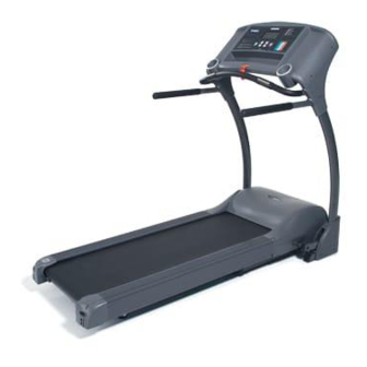
- Page 1 OWNER’S MANUAL 5.45 MOTORIZED TREADMILL USER WEIGHT LIMITATION: 275LBS SERIAL NUMBER (Found on Frame): Copyright © 2008-1...
- Page 2 ...
-
Page 3: Motorized Treadmill
• When connecting the power cord, plug the power cord into a grounded circuit. No other appliance should be on the same circuit. • Always straddle the belt and allow it to start moving before stepping onto the belt. • Always examine your treadmill before using to ensure all parts are in working order. • Allow the belt to fully stop before dismounting. • Never insert any object or body parts into any opening. • Follow the safety information in regards to plugging in your treadmill. • Keep the power cord away from the incline wheels and do not run the power cord underneath your treadmill. Do not operate the treadmill with a damaged or frayed power cord. • Always unplug the treadmill before cleaning and/or servicing. Service to your treadmill should only be performed by an authorized service representative, unless authorized and/or instructed by the manufacturer. Failure to follow these instructions will void the treadmill warranty. • Never leave the treadmill unattended while it is running. • The equipment is for Class B (Home Use). 5.45 MOTORIZED TREADMILL... -
Page 4: Power Requirements
5.45 MOTORIZED TREADMILL POWER REQUIREMENTS Power Requirements: IMPROPER CONNECTION OF THE EQUIPMENT GROUNDING CONNECTOR CAN RESULT IN A RISK OF AN ELECTRIC SHOCK. CHECK WITH A QUALIFIED ELECTRICIAN OR SERVICE MAN IF YOU ARE IN DOUBT AS TO WHETHER THE PRODUCT IS PROPERLY GROUNDED. DO NOT MODIFY THE PLUG PROVIDED WITH THE PRODUCT, IF IT WILL NOT FIT THE OUTLET; HAVE A PROPER OUTLET INSTALLED BY A QUALIFIED ELECTRICIAN. This treadmill can be seriously damaged by sudden voltage changes in your home’s electrical power. Voltage spikes, surges and noise interference can result from weather conditions or from other appliances being turned on or off. To reduce the possibility of treadmill damage, always use a surge protector (not included) with your treadmill. Surge protectors can be purchased at most hardware stores. The manufacturer recommends a single outlet surge protector with a UL 1449 rating as a Transient Voltage Surge Suppressor (TVSS) with a UL suppressed voltage rating of 400V or less and an electrical rating 110VAC, 15 amps. This treadmill must be grounded to reduce the risk of electrical shock. Grounding provides a path of least resistance for electric current, should the treadmill malfunction. This treadmill comes with an electrical cord having an equipment‐grounding conductor and a grounding plug. Always plug the power cord into a surge protector, and plug the surge protector into an appropriate outlet that is properly installed and grounded in accordance with all local codes and ordinances. This product is for use on a nominal 110‐volt circuit, and has a grounding plug that looks like the plug illustrated in the drawing below. GFCI outlets and GFCI Circuit Breakers are NOT recommended for use on this product. GFCI outlets and GFCI Circuit Breakers may cause this equipment to improperly function . ... -
Page 5: Before You Begin
Invite a friend: Some of the assembly steps may require heavy lifting. It is recommended that you obtain the assistance of another person when assembling this product. User Weight Limitation: Please note that there is a weight limitation for this product. If you weigh more than 275LBS. It is not recommended that you use this product. Serious injury may occur if the user’s weight exceeds the limit shown here. This product is not intended to support users whose weight exceeds this limit. Care and maintenance: 1. The safety level can be maintained only if it is examined for damage and wear. 2. Replace any defective components immediately and stop all use of equipment until repaired. 3. Always take care when you mounting the equipment . Straddle the equipment by placing your feet on the straddle rails . . Dismount from the equipment only after all parts have stopped.. 4. Always check the easily wear components like pulley etc. To prevent danger. 5. There is an emergency stop to prevent dangers, you can stop the treadmill immediately by actuated the emergency stop for emergency dismount. 5.45 MOTORIZED TREADMILL ... -
Page 6: Supplied Components
5.45 MOTORIZED TREADMILL SUPPLIED COMPONENTS This list identifies the major components you will use to assemble this product. Component A , B and C are already partially assembled . No. Description A Main Frame Assembly B Front handlebar C Side handlebar 108 Water Bottle Holder 207 Handle Bar Cover ‐ LL 208 Handle Bar Cover ‐ LR 209 Handle Bar Cover ‐ RL 210 Handle Bar Cover ‐ RR 302 Upright Base Cover ‐ LL 303 Upright Base Cover ‐ LR 304 Upright Base Cover ‐ RL 305 Upright Base Cover ‐ RR Qty. 1 ... -
Page 7: Supplied Hardware
805 M8×45 Bolt 2 810 M8×18 Bolt 8 811 M8×52 Bolt 2 812 Ø8 Washer 12 M8×75 Bolt 2 845 Screw Driver 1 A Allen Key 1 B Allen Wrench 1 C Safety Key 1 107 Power Cord 1 E MILLIMETERS 5.45 MOTORIZED TREADMILL ... -
Page 8: Complete Parts List
5.45 MOTORIZED TREADMILL COMPLETE PARTS LIST Part No. Description Complete Computer Console Components 100 101 Overlay 102 Computer PC Board 103 Console Plate 104 Console Housing ‐ Upper 105 Console Housing ‐ Bottom 106 Safety Key Base 107 Safety Key 108 Water Bottle Holder 110 Plastic Fixing Insert 111 Hand Pulse Wire ‐ upper 200 Complete Handle Bar Components 201 Front Handle Bar Tube 202 Handle Bar 203 Handle Bar Upright Foam Grip ... - Page 9 Rubber Cushion Complete Running Deck Components 601 Running Belt 602 Side Rail 603 Running Deck 604 Side Rail End Cap ‐ Left 605 Side Rail End Cap ‐ Right 606 Cushion Pad 5.45 MOTORIZED TREADMILL Qty. Order No. 5.45‐401 2 5.45‐402 2 5.45‐403 1 5.45‐404 1 5.45‐405 1 5.45‐406 1 5.45‐407 1 5.45‐408 ...
- Page 10 5.45 MOTORIZED TREADMILL COMPLETE PARTS LIST Part No. Description 607 Main Frame Cross Bar Complete Deck Frame Components 700 701 Deck Frame 702 Front Roller Shaft 703 Front Roller Tube 704 Rear Roller Shaft 705 Rear Roller Tube 706 Running Deck Rear Wheel 707 Cushion Pad Complete Hardware Pack 800 801 M3.5×16 Screw 802 M4×15 Screw 803 M3×10 Screw 804 Ø 4 Washer ...
- Page 11 5.45 MOTORIZED TREADMILL Qty. Order No. 1 5.45‐830 1 5.45‐831 2 5.45‐832 1 5.45‐833 4 5.45‐834 4 5.45‐835 16 5.45‐836 2 5.45‐837 ...
-
Page 12: Parts Diagram
5.45 MOTORIZED TREADMILL PARTS DIAGRAM ... - Page 13 PARTS DIAGRAM 5.45 MOTORIZED TREADMILL ...
- Page 14 5.45 MOTORIZED TREADMILL PARTS DIAGRAM ...
- Page 15 5.45 MOTORIZED TREADMILL PARTS DIAGRAM ...
- Page 16 5.45 MOTORIZED TREADMILL PARTS DIAGRAM 812 826 ...
- Page 17 PARTS DIAGRAM 5.45 MOTORIZED TREADMILL ...
- Page 18 5.45 MOTORIZED TREADMILL PARTS DIAGRAM ...
- Page 19 ASSEMBLY STEP 1: Unpacking and Inventory NOTE: FOR SAFER AND EASIER TRANSPORTATION DO NOT REMOVE THE PLASTIC RETAINING STRAPS UNTILL THE UNIT IS IN THE AREA OF ASSEMBLY Remove the treadmill and all the components and hardware from the box. Check the quantities of all components and hardware with the component and hardware lists on pages 5‐6. 5.45 MOTORIZED TREADMILL Warning !!! P.5 Components Hardware and Tools P.6 ...
- Page 20 5.45 MOTORIZED TREADMILL ASSEMBLY STEP 2: Assemble Upright Frame NOTE : Make sure all wires are recessed into the frame , DO NOT trap or pinch (Hand tight bolts until last step ) A. Raise the left and right uprights (301) . B. Secure the left upright (301) with two 8x18 mm Allen bolts (810) and two Ø8 washer (812) through the front side of the base frame . hand tighten . C. Secure the right upright (301) with two 8x18 mm Allen bolts (810) and two Ø8 washer (812) through the front side of the base frame . hand tighten . D. Insert one M 8x52 mm Allen bolt (811) and one Ø8 washer (812) through the side of the base frame and the left upright , hand tighten . Insert one M 8x52 mm Allen bolt (811) and one Ø8 washer (812) through the side of the base frame and the right upright , hand tighten . Tighten all Allen bolts with Allen wrench C (Provided with hardware). X2 810 X4 812 X6 ...
- Page 21 C. Secure right side with one Ø8 washer (812) and M8x45 mm Allen bolt (805) in the forward most hole . Connect pulse wire (217) and wire (111) on left and right side (as shown in diagram) . Then insert the remaining length of the wire into the front handle bar tube . Tighten all bolts with Allen Wrench . 5.45 MOTORIZED TREADMILL X2 X2 ...
- Page 22 5.45 MOTORIZED TREADMILL ASSEMBLY STEP4: Assemble The Side Handlebars NOTE: Side rails are interchangeable for use on both right and left sides Attach one handlebar (202) to the left upright (301) Secure the Side Handlebar with one M8 x75 mm bolt (845) and one Ø8 washer (812),through the top of front handle bar into the side handle bar . Insert two M8x18 mm (810) and two Ø8 washer (812) through the side handrail plate and thread into the upright . ...
- Page 23 M4×15mm screw (802) between the Handle Bar Cover ‐ LR (208) outside and the console housing ‐upper. Attach the Handle Bar Cover ‐ LL (207) to the top of the console and the outside of the Upright ‐ Left (301).And secure with four M4×15mm screw (802). Repeat the above process for the right hand side cover (209) and cover (210) as shown in diagram. 5.45 MOTORIZED TREADMILL 802 X20 ...
- Page 24 5.45 MOTORIZED TREADMILL ASSEMBLY STEP 6: Assembly base covers NOTE : Refer to folding instructions on page 27 . A. Fold up the running deck until it locks in place . B. Attach Upright Base Cover (302) to the outside of the Left Upright (301). Secure with two M4x15 mm screw (802). C. Attach Upright Base Cover (303) to the inside of the Left Upright (301). Secure with one M4x15 mm screw (802). D. Attach Upright Base Cover (305) to the outside of the Right Upright (301). Secure with three M4x15 mm screw (802). Attach Upright Base Cover (304) to the inside of the Right Upright (301). Secure with one M4x15 mm screw (802). 802 X7 ...
- Page 25 5.45 MOTORIZED TREADMILL ASSEMBLY STEP7: Attaching Rubber Cover Insert the rubber cover (306) into the slot upright base cover . ...
- Page 26 5.45 MOTORIZED TREADMILL ASSEMBLY STEP 8: Inserting Water Bottle Holders Attach the Water Bottle Holder ( 108) to the Console Housing ‐ Upper ( 104) and push down until snap in place. ...
- Page 27 Safety Features 5.45 MOTORIZED TREADMILL There are two orange levers on this treadmill. The most forward lever is the folding lock which is used in folding and unfolding this treadmill. The other is used for transporting from one location...
-
Page 28: Folding Instructions
FOLDING INSTRUCTIONS How to fold up the treadmill: Your treadmill can be folded up for space saving storage. To do this follow the instructions here: Listen for the click of the Folding Level locking mechanism . Be sure locking mechanism is engaged before transporting . Lift the deck from the rear towards the computer console. (Transportation instruction on pg 29 ) 5.45 MOTORIZED TREADMILL ... -
Page 29: Unfolding Instructions
5.45 MOTORIZED TREADMILL UNFOLDING INSTRUCTIONS How to unfold the treadmill: NOTE: To maintain stability make sure the rear transportation wheel is disengaged before unfolding treadmill To unfold the treadmill for use follow the instructions here: Release Lever Push the deck towards the computer console . Depress the Folding Level begin lowering the treadmill towards the floor release the folding level . Lower treadmill deck towards floor . ... -
Page 30: Transport Instructions
5.45 MOTORIZED TREADMILL TRANSPORT INSTRUCTIONS TRANSPORT INSTRUCTIONS: NOTE : Transport wheel must be down as picture below . To roll away for storage simply grab the rear deck, lift slightly and roll to desired location. Lift the deck from the rear so that the treadmill rests on the front transportation wheels and on the rear transportation wheel engages Roll to a desired location. ... -
Page 31: Computer Operation
1). Press to decrease exercise speed by 0.1MPH/KPH. 2). Hold the button to rapidly decrease speed by 0.5MPH/KMPH per second and release the button to stop the function. INCLINE UP / DOWN 1). Press up or down to change incline level. 2). Press to select programs and preset related function value. SAFETY KEY The safety key must be inserted into the slot on the console in order to operate the treadmill. Always insert the safety key and attach the clip to your clothing at your waist before beginning your workout. If you should encounter problems and need to stop the motor quickly, simply pull on the cord to disengage the safety key from the console. To continue operation first turn the power switch to off and set the speed controller to stop. Next turn the power switch to on and reinsert the safety key into the console. A B C D E F A B C D E F 5.45 MOTORIZED TREADMILL INCLINE UP/DOWN Button SPEED UP/DOWN Button Display Window... - Page 32 5.45 MOTORIZED TREADMILL COMPUTER OPERATION POWER ON Set the POWER SWITCH, located on the base frame, to ON and insert the SAFETY KEY. The UPPER LCD and LOWER LCD screens light up all digits and enter the POWER ON mode. The UPPER LCD SPEED/DISTANCE window shows “0.0” and 6 program LED lights blink individually. The LOWER LCD shows 0 on all windows. SLEEP MODE When the power is ON the computer will automatically enter SLEEP MODE if it is left idle for 3 minutes without receiving any input. Press any button to return to POWER ON status when the computer is in the SLEEP MODE. DISPLAY MODE This feature is designed only for store display purpose. To cancel the SLEEP MODE feature, pull out the safety key, press and hold the SPEED UP and DOWN buttons, insert the safety key to power on the treadmill. After one short beep sound, the SLEEP MODE will be cancelled and the LCD will not go off as long as the power switch stays on and the safety key is inserted properly. ENGLISH / METRIC CONVERSION The computer has been preset to calculate and show all information in English (miles, pounds, inches). The computer can be set to display information in Metric (kilometers, kilograms, centimeters). To do this set the POWER SWITCH, located on the base frame, to ON. Press and hold the START button. Insert the SAFETY KEY. The computer will sound one short BEEP and the UPPER LCD will show KM and blink. Press the INCLINE UP/DOWN button to switch between KM and ML. KM means Metric and ML means English. Press the STOP/ENTER button to confirm the setting and return to POWER ON status after one long beep sound. QUICK START When the treadmill is in POWER ON status, press the START button to activate the QUICK START. The SPEED LCD counts down 3 seconds with 3 short beeps then starts from 0.5 MPH/0.8 KPH. Press the SPEED UP/DOWN buttons to adjust the speed. ...
- Page 33 5.45 MOTORIZED TREADMILL COMPUTER OPERATION SET USER HEIGHT After setting the user weight, the lower LCD will display H. The CALORIES LCD display now shows the blinking factory setting user height 5’3”/160CM. Press the INCLINE UP/DOWN buttons to adjust the user height correctly and press STOP/ENTER to set the user height. SET USER AGE After setting the user weight, the lower LCD will display A. The INCLINE LEVEL LCD display now shows the blinking factory setting user age 35. Press the INCLINE UP/DOWN buttons to adjust the user age correctly and press STOP/ENTER to set the user age. SET USER TARGET HEART RATE When you set up the user AGE, please note the user TARGET HEART RATE will be adjusted with the user AGE according to the factory setting. The factory TARGET HEART RATE setting is based on 85% of the maximum heart rate. The maximum heart rate is calculated as 220 minus the user age. For age 35, the maximum user heart rate should be 185 and 85% of user heart rate, which is 157. After setting the user age, the lower LCD will show P and the PULSE LCD shows the blinking factory target heart rate setting. Press the INCLINE UP/DOWN buttons to adjust the user target heart rate properly for your own physical condition and press the STOP/ENTER button to set the user TARGET HEART RATE. Now, you have completed the user information set up. For the 2 or other member in the family, please assign a different user ID. This treadmill can allow set and memorize 9 different user’s information. For the repeat user, after pressing the program button, please press the INCLINE UP/DOWN buttons to select the USER ID that you assigned previously. Each time when the treadmill is switched off and switched on again it will enter the select program procedure. The user ID will show the user ID of the previous user. OPERATE PROGRAM After completing the USER INFORMATION SET UP, prior to starting the program you selected, please follow the procedure to operate the different programs as described below: ...
-
Page 34: Min. Level
5.45 MOTORIZED TREADMILL COMPUTER OPERATION During the workout, press the SPEED UP/DOWN buttons to adjust the speed. Users can overwrite the incline level by pressing the INCLINE UP/DOWN buttons. COOL DOWN After the pre‐set TIME counts down to 0, treadmill will start a one minute cool down program. The TIME LCD will display COOL and blink for 10 seconds and continue counting down 50 seconds at speed 2 MPH/3.2KPH. After a one minute cool down, the treadmill will stop and return to P2 start display. Press STOP/ENTER to go to POWER ON status. P3 INTERVAL SPEED If you select the P3 INTERVAL SPEED program, the upper and lower LCD will show the following: After completing the user information set up, the SPEED, CALORIES and PULSE LCD display 0. The TIME display shows factory setting 24:00 and a blinking workout load level shows 1. Press the INCLINE UP/DOWN buttons to adjust the workout load level from 1 to 12 then press the STOP/ENTER button to confirm the setting. Then the TIME LCD will display a blinking 24:00. Press the INCLINE UP/DOWN buttons to adjust the total workout time and press STOP/ENTER button to confirm the setting. Press the START button to start the workout. The SPEED start and change follows the pre‐set workout load speed chart as below. The TIME counts down from the set up workout time. The CALORIES and DISTANCE count up from 0. INCLINE LEVEL starts from level 0. During the workout, press the INCLINE UP/DOWN button to adjust the incline level. Users can overwrite the speed by pressing the SPEED UP/DOWN buttons. COOL DOWN After the pre‐set TIME counts down to 0, the treadmill will start a one minute cool down program. The TIME LCD will display COOL and blink for 10 seconds and continue counting down 50 seconds at a speed of 2MPH/3.2KPH. After the one minute cool down, the treadmill will stop and return to P2 start display. Press STOP/ENTER to go to POWER ON status. ... - Page 35 COOL and blink for 10 seconds and continue counting down 50 seconds at a speed of 2MPH/3.2KPH. After a one minute cool down, the treadmill will stop and return to P2 start display. Press STOP/ENTER to go to POWER ON status. MAX. SPEED MINI. INCLINE LEVEL 1.6 1.8 2.0 2.2 2.4 2.6 2.8 3.0 3.2 5.45 MOTORIZED TREADMILL MAX INCLINE LEVEL 3 4 5 6 7 8 9 10 11 ...
- Page 36 5.45 MOTORIZED TREADMILL COMPUTER OPERATION P6 HEART RATE CONTROL If you select the P6 5K HEART RATE CONTROL program, the LCD will show the following: After completing the user information set up, the TIME LCD shows the blinking factory pre‐set workout time 60:00. Press the INCLINE UP/DOWN buttons to adjust the workout time and press the STOP/ENTER button to confirm. Then the upper LCD shows initial speed 2.0MPH/3.2KPH and the lower LCD shows initial warm up time 3:00. Press the START button to start the 3 minutes WARM UP program. Speed starts from 2.0MPH/3.2KPH and INCLINE LEVEL starts from level 0. Please keep your hand on the hand pulse grips all the time during this workout in order to monitor your pulse correctly. During the program, if the heart rate monitor fails to sense the pulse you will see P blinking on the PULSE LCD. If the heart rate monitor senses the pulse properly you will see the stable heart beat sign on the PULSE LCD and the correct pulse readout on the PULSE LCD. The computer will sense the user pulse every 30 seconds. During the warm up program you can press the STOP/ENTER button to pause or stop the program or press the START button to re‐start the program. Other buttons will not react during this warm up process. During the warm up program if heart rate monitor fails to sense the user’s pulse (The PULSE LCD will display P and blink), the computer will not change the speed. If heart rate monitor senses the user’s pulse properly and the actual user’s pulse does not reach 65% of the maximum heart rate ((220‐age) x 65%), then speed will increase by 0.5MPH/0.8KPH per 30 seconds. If the actual pulse reaches 65% of the maximum heart rate, the speed will remain unchanged. If the actual pulse reaches 65% of the maximum heart rate over one minute, then the speed will be maintained the same until the warm up program finishes. If the actual user’s pulse fails to reach 65% of the maximum heart rate within the first 3 minutes of warm up, the computer will continue the second 3 minutes warm up program. All workout information continues to count up and the timer counts ...
-
Page 37: Maintenance
Belt adjustment and tension performs two functions: adjustment for tension and centering. The running belt has been adjusted properly at the factory. However transportation, uneven flooring or other unpredicted reasons could cause the belt to shift off center resulting in the belt rubbing with the plastic side rail or end caps and possibly causing damage. To adjust the belt back to it’s proper position please follow the directions below: • Walking belt has shifted to the left: First unplug the power cord from the surge protector. Using the hex key provided, turn the left rear roller adjustment bolt 1/4 turn in the clockwise direction. Plug the power cord back into the surge protector and run the treadmill at 2.5 mph. You should see the belt start to correct itself, moving back towards the center. Repeat the above procedure until the walking belt is centered. It may be necessary to set walking belt tension once you have completed this procedure if the belt feels like it is slipping while walking. Refer below to the "Walking belt slipping" instructions. • Walking belt has shifted to the right: First unplug the power cord from the surge protector. Using the hex key provided, turn the right rear roller adjustment bolt 1/4 turn in the clockwise direction. Plug the power cord back into the surge protector and run the treadmill at 2.5 mph. You should see the belt start to correct itself, moving back towards the center. Repeat the above procedure until the walking belt is centered. It may be necessary to set walking belt tension once you have completed this procedure if the belt feels like it is slipping while walking. Refer below to the "Walking belt slipping" instructions. • Walking belt is slipping: First unplug the power cord from the surge protector. Using the hex key provided, turn both the left and right rear roller adjustment bolts the same distance, usually a 1/2 turn in the clockwise direction. Plug the power cord back into the surge protector and run the treadmill at 2.5 mph. You should now walk on the belt to determine if the belt is still slipping. Repeat the above procedure until the walking belt is not slipping. The tension should be just tight enough not to slip. WARNING! Do not over tighten rollers! This will cause premature roller bearing failure! Right and left tension bolts are located at the rear of the treadmill. 5.45 MOTORIZED TREADMILL ... -
Page 38: Deck Lubrication
5.45 MOTORIZED TREADMILL MAINTENANCE CLEANING: Routine cleaning of your treadmill will extend the product's life. Warning: To prevent electrical shock, be sure the power to the treadmill is OFF and the power cord is unplugged from the wall electrical outlet before attempting any cleaning or maintenance. Important: Do not use abrasives or solvents to clean the treadmill. To prevent damage to the computer, keep liquids away and keep it out of direct sunlight. After each workout: Wipe off the console and other treadmill surfaces with a clean, water dampened soft cloth to remove excess perspiration. Weekly: Use of a treadmill mat is recommended for ease of cleaning. Dirt from your shoes contacts the belt and eventually makes it to underneath the treadmill. Vacuum underneath treadmill once a week. DECK LUBRICATION: The walking belt has been pre‐lubricated at the factory. However, it is recommended that the walking board be checked periodically for lubrication to ensure optimal treadmill performance. Your treadmill should not have to be lubricated usually within the first 400 hours of use. Every 2 months of operation lift the sides of the walking belt and feel the top surface of the walking board as far as you can reach. If you feel signs of silicone, no further lubrication is required. If it feels dry to the touch, follow the instructions below. Please use Lube 'N Walk (can be purchased from your dealer or call the number on the front of the manual), or a non‐petroleum based silicone such as "Napa 8300" (available at most stores). To purchase lubricant kit please contact Smooth Fitness 1‐888‐800‐1167 To apply lubricant to the walking belt: ... -
Page 39: Warranty
• Model name or number from the cover of the manual; • Serial number located on the frame of the unit; • The part description and the order number. Limitations on Warranty: This Warranty does not cover wear and tear, any problems, damages or failures that are caused by accident, improper assembly, failure to observe cautionary labels on the product, failure to operate the product correctly, abuse or freight damage. Smooth Fitness does not warrant against any damage or defects that may result from repair or alterations made to the product by an unauthorized repair facility. This Warranty does not apply to any product shipped or handled outside of Germany, Austria and England. This Warranty does not apply if the product is used as a rental product or in commercial use, Consequential and incidental damages are not recoverable under this Warranty. THIS WARRANTY IS EXPRESSLY IN LIEU OF ALL OTHER EXPRESS WARRANTIES. ALL IMPLIED WARRANTIES, INCLUDING WARRANTIES OF MERCHANTABILITY OR FITNESS FOR ANY PARTICULAR PURPOSE, ARE LIMITED IN DURATION TO ONE (1) YEAR FROM THE EFFECTIVE DATE OF THIS WARRANTY. SMOOTH FITNESS IS NOT LIABLE FOR CONSEQUENTIAL OR INCIDENTAL DAMAGES RESULTING FROM ANY DEFECT IN PARTS NOR FOR ANY BREACH OF EXPRESS OR IMPLIED WARRANTIES. SMOOTH FITNESS' SOLE LIABILITY UNDER THIS WARRANTY IS LIMITED TO THE TERMS DESCRIBED IN THIS FORM. THIS WARRANTY GIVES YOU SPECIFIC LEGAL RIGHTS, AND YOU MAY ALSO HAVE OTHER RIGHTS WHICH VARY FROM STATE TO STATE. Frame Drive Motor Parts & Electronics Lifetime Lifetime 3 years 5.45 MOTORIZED TREADMILL Labor 1 year ... -
Page 40: Important Steps
5.45 MOTORIZED TREADMILL IMPORTANT STEPS Warning: Before using this product, please consult your personal physician for a complete physical examination. Frequent and strenuous exercise should be approved by your doctor first. If any discomfort should result from your use of this product, stop exercising and consult your doctor. Proper usage of this product is essential. Please read your manual carefully before exercising. Please keep all children away from the equipment during use and when equipment is unattended. Always wear appropriate clothing, including athletic shoes, when exercising. Do not wear loose clothing that could become caught during exercising. Make sure that all bolts and nuts are tightened when equipment is in use. Periodic maintenance is required on all exercise equipment to keep it in good condition. Before beginning: How you begin your exercise program depends on your physical condition. If you have been inactive for several years, or are severely overweight, you must start slowly and increase your time gradually, a few minutes per week. Initially you may be able to exercise only for a few minutes in your target zone. However, your aerobic fitness will improve over the next six to eight weeks. Don’t be discouraged if it takes longer. It’s important to work at your own pace. Ultimately, you’ll be able to exercise continuously for 30 minutes. And the better your aerobic fitness, the harder you will have to work to stay in your target zone. But remember these essentials: • Contact your physician before starting a workout or training program. Have your doctor review your training and diet programs to advise you of a workout routine you should adopt. • Begin your training program slowly with realistic goals that have been set by you and your doctor. •... -
Page 41: Target Heart Rate
25 30 35 40 45 YOUR AGE ADVANCED: Sports, athletic conditioning or interval training FITNESS: Optimal training, aerobic or cardiovascular HEALTH: Beginner, low intensity with long duration produces fat burning 5.45 MOTORIZED TREADMILL ... -
Page 42: Muscle Chart
5.45 MOTORIZED TREADMILL MUSCLE CHART Targeted muscle groups: The exercise routine that is performed on this product will develop primarily lower body muscle groups. These muscle groups are shown in gray color on the chart below. A Shoulder muscles B Pectoral muscles C Bicep muscle D Abdominal muscles E Forearm muscles F Quadriceps muscles MUSCLE GROUPS Calf muscles Trapeziums muscles Triceps muscles Back muscles Gluteus muscles Hamstring muscles G H ... -
Page 43: Stretching Routine
Repeat this action with your left arm. Rotate your head to the right for one count, feeling the stretch up the left side of your neck. Next, rotate your head back for one count, stretching your chin to the ceiling and letting your mouth open. Rotate your head to the left for one count, and finally, drop your head to your chest for one count. 5.45 MOTORIZED TREADMILL Lift your right shoulder up toward your ear for one count. Then lift your left shoulder up for one count as you lower your right shoulder. Sit with your right leg extended. Rest the sole of your left foot against your right inner thigh. Stretch toward your toe as far as possible. Hold for 15 counts. Relax and then repeat with left leg extended. -
Page 44: Troubleshooting
5.45 MOTORIZED TREADMILL TROUBLESHOOTING NOTE: Do not touch any internal electric wires without consulting the manufacturer. Treadmill will not start: Symptom Treadmill will not power up Treadmill stops operation during use Treadmill will not incline (Power fold models only) Treadmill will not unfold Treadmill running belt moves slower than speed displayed on computer Treadmill running belt moves slower than speed displayed on computer Running belt is not centered Running belt is slipping or hesitating while in use Treadmill running belt moves slower than speed displayed on computer Running belt is not centered Running belt is slipping or hesitating while in use Resolution Check the following: ▪ Make sure the power cord is plugged into a surge protector, the surge protector is plugged into a properly grounded outlet and the surge protector is turned on (refer to the Power Requirements ... - Page 45 Copyright © 2008 Greenmaster Industrial Corp. All rights reserved. ...
Need help?
Do you have a question about the 5.45 and is the answer not in the manual?
Questions and answers