Advertisement
Advertisement
Table of Contents

Related Manuals for Ascon tecnologic XS Series


Summary of Contents for Ascon tecnologic XS Series
- Page 1 Configurable Multi-input, Multi-output or Ascon Tecnologic S.r.l. Multi-set point Controller via Indipendenza 56, 27029 - Vigevano (PV) Series Tel.: +39 0381 69871, Fax: +39 0381 698730 INSTRUCTION MANUAL MIU.XS-6/96.10/E COD J30-154-1AXS ING Ascon Tecnologic Srl www.ascontecnologic.com...
-
Page 2: Table Of Contents
GENERAL INDEX DENTIFICATION OF MODEL ........page 1 FUNCTION OF KEYS AND DISPLAYS......page 3 DIMENSIONS, INSTALLATION ........page 6 ELECTRICAL WIRING..........page 7 Y2 - Y3 AUXILIARY OUTPUTS ........page 13 PASSWORDS ............... page 15 PROGRAMMING PROCEDURE (see enclosed leaflet) CONFIGURATION PARAMETERS... -
Page 3: Dentification Of Model
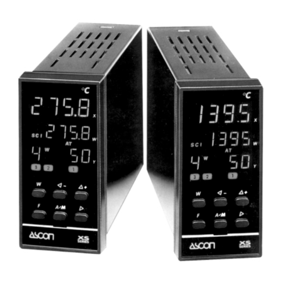
1 • IDENTIFICATION OF MODEL Thank you for choosing an ASCON controller The instruments of the XS series belong to the last generation of microprocessor based controller, are universal, very powerful but simple to use. They are fitted with AUTO-TUNE and EXPERT-TUNE, an auxiliary for system start-up, and serial communication for introduction into a distributed control network. - Page 4 1 • IDENTIFICATION OF MODEL 1.2 Configuration code Configuration code Beginning and end of scale F G H I L M N Model code 275. 8 Input X 275. 8 Main output Y1 Auxiliary output Y2 Auxiliary output Y3 Retransmission output Y4 Set point W Beginning and end of scale (for configurable scales only)
-
Page 5: Function Of Keys And Displays
2 • FUNCTION OF KEYS AND DISPLAYS Auto-tune in course Measurement X 275. 8 Waiting - programme in course Active Remote Set Set point W 275. 8 Active serial communication Manual operation Mem. programme in execution Main output % Y1 Main output Y1 “ON”... - Page 6 2 • FUNCTION OF KEYS AND DISPLAYS LEDS FOR OUTPUT STATE Lit with output Y1 “ON” 7 - Output Y1 (red) De-activated with continuous or dual action discontinuous output 7a - Output Y1 (heat) Lit with output Only for HEAT/COOL Y1 (heat) “ON”...
- Page 7 2 • FUNCTION OF KEYS AND DISPLAYS KEYS 16 - Set Point Standard configuration: (1 Local + 4 storable used for: • modifying the Set point • recalling the 4 memorized Set points (see enclosed leaflet) Remote Set configuration: (1 Local + 1 Remote) used for: •...
-
Page 8: Dimensions, Installation
3 • DIMENSIONS - INSTALLATION 3.1 - Overall dimensions (in compliance with DIN 43700) 60 min. 65 min. with protection IP65 110 min. 150 min. with protection IP65 Ring with hook Front cover and locking screw projection +0.8 +0.6 Advised thickness 1 ÷... -
Page 9: Electrical Wiring
4 • ELECTRICAL WIRING A • T erminal boar d B • Freeing the terminals 28 screw terminals M3.5 Lift the plate to free Plate pin the pin Wiring protection plate Rotate downwards Plate screw Cold joint 3 gilded compensation terminals for thermometer input signals... - Page 10 4 • ELECTRICAL WIRING Although this controller is designed to resist the heaviest disturbances present in industrial environments (level IV of standard (IEC 801-4), it is advised to keep to the following precautions: Precautions Advised conductor course Power supply and output channels Single out supply line from power line Keep away from teleruptors,...
- Page 11 4 • ELECTRICAL WIRING Schema di collegamento 1 • Single power supply "Switching" type • Standard: 100 to 240 Vac - 15% + 10% • for low tension: 24 Vac -15% + 10% Single power supply 24 Vdc ±15% Absorbed power 4VA 2 •...
- Page 12 4 • ELECTRICAL WIRING Schema di collegamento 3 • Remote Set point input Rj = 30 Ω per mA In current 4..20 mA Ri = 330 KΩ per V In voltage 0..10 Vdc NOT galvanically Remote Set point mA, Volt isolated 4 •...
- Page 13 4 • ELECTRICAL WIRING 5 • Main output Y1 (continued) B • single in current Continuous output 4..20mA Load galvanically isolated 450 Ω max. C • single in voltage Continuous Load Position the switch set output 0..10Vdc inside the controller too 500 Ω...
- Page 14 4 • ELECTRICAL WIRING 6 • Auxiliary outputs Y2 (see p. 13) Load NA contacts, capacity 5A/250Vac for resistive loads (transitions 2x10 (coeff.5) min. at 5A/250Vac) Load 7 • Retransmission output Y4 (option) Load Galvanically isolated 4..20mA, 10Vdc max. or 500 Ω...
-
Page 15: Y2 - Y3 Auxiliary Outputs
5 • Y2 - Y3 AUXILIARY OUTPUTS Deviation Active high Set point W (1) (above) -300...+300 steps compared to W1 Active low (under) ∆W -300 steps +300 steps Band Active out Set point I WI (1) (above) -0...300 steps compared to W1 Active in (under) I∆WI... - Page 16 5 • Y2 - Y3 AUXILIARY OUTPUTS “Loop-Break-Alarm” LBA (control loop defect/interruption) Any interruption in the connections 275. 8 or any anomaly in the operation of 275. 8 one of the control loop components, will cause the output Y3 to be energized after a few minutes and front display X and W will be flashing.
-
Page 17: Passwords
6 • PASSWORD In order to prevent tampering or inadvertent alterations of the configuration or of some important parameters at the programming stage, 2 passwords have to be entered. 3333 6.1 Password of access to configuration 3333 Enter password of access to configuration W p Ass (see enclosed leaflet)) Return to normal... -
Page 18: Set Point
9 • MODIFYING THE OPERATING STATE Modifications may be carried out through: commands from keyboard external contacts on logic inputs 275. 8 External contacts 275. 8 commands via serial 275. 8 see separate manual 275. 8 20mA C.L. RS232 Interface With external contacts on logic inputs IL1, IL2, IL3 Impulsives closing for at least 2 sec., of contacts C1, C2, C3, permits modification of state or of Set point. -
Page 19: Technical Data
12 • TECHNICAL DATA 0.2% ± 1 digit (for input with RTD Pt100 and thermocouples) Accuracy (a25°C amb.) 0.1% ± 1 digit (for input in current and voltage) RTD Pt100 Pt100Ω @ 0°C, (IEC 751) Input "X" With Thermocouples J-K-S-R (IEC 584), L (DIN 43710) (configurable) configurable scale field... - Page 20 12 • TECHNICAL DATA Single or dual, with direct or reverse action Relay with dual action 2 contacts NA, 5A/250Vac, 2x10 coeff.5 transitions Discontinuous Main output Logic 0.18 Vdc, 20mA max. (for static relays) galvanically (configurable) Current 4..20mA(450Ω max.,10 Volts max.) isolated Continuous Voltage...
- Page 21 18 months after delivery. Faults caused by use other than that described in these operating instructions are excluded from the guarantee. Ascon Tecnologic S.r.l. via Indipendenza 56, 27029 - Vigevano (PV) Tel.: +39 0381 69871, Fax: +39 0381 698730...
Need help?
Do you have a question about the XS Series and is the answer not in the manual?
Questions and answers