Table of Contents
Advertisement
Quick Links
Advertisement
Table of Contents

Related Manuals for EXFO MaxTester Max-610


Summary of Contents for EXFO MaxTester Max-610
- Page 1 User Guide MaxTester MAX-610 Copper Test Set...
-
Page 2: Copyright Information
EXFO Inc. (EXFO). Information provided by EXFO is believed to be accurate and reliable. However, no responsibility is assumed by EXFO for its use nor for any infringements of patents or other rights of third parties that may result from its use. -
Page 3: Table Of Contents
3 Getting Started with the MaxTester ............13 Turning the Unit On/Off ......................13 Using Menus and Keypad .....................14 Keypad ..........................15 Using Online Help .........................15 4 Setting Up the MaxTester MAX-610 ............17 Home ............................17 System Settings ........................18 Display and Language ......................19 Date and Time ........................20 Power ...........................21... - Page 4 Contents 5 Setting Up Copper Tests ................35 Copper Test Main Menu ......................35 Test Configuration ........................36 Setup ............................43 Phone Book ..........................44 Dialer Function ........................52 Cable Book ...........................57 Application Settings ......................63 Test Lead Compensation .......................72 FED Setup ..........................73 Saving Results ........................79 6 Reading Saved Copper Test Results ............83 Read/Upload Result .......................83 Results Summary ........................83 Read Result Menu .........................84...
- Page 5 Contents 10 Frequency Tests ..................173 Frequency Tests Main Page ....................173 VF/AC Balance ........................174 WB Balance .........................180 WB Attenuation ........................185 Load Coils ...........................192 Locator Tone ........................195 TX/RX Tone ..........................197 11 TDR ......................201 Continuous .........................201 Cable Setup ........................205 Load Trace ..........................206 Result Details ........................207 TDR Profile Details ......................212 12 RFL ......................
- Page 6 Contents 16 Warranty ....................259 General Information ......................259 Liability ..........................260 Exclusions ...........................261 Certification ........................261 Service and Repairs ......................262 EXFO Service Centers Worldwide ..................263 ............................263 A Technical Specifications ................265 Index .......................269 MAX-610...
-
Page 7: Certification Information
Electronic test and measurement equipment is exempt from FCC part 15, subpart B compliance in the United States of America and from ICES-003 compliance in Canada. However, EXFO Electro-Optical Engineering Inc. makes reasonable efforts to ensure compliance to the applicable standards. -
Page 8: European Community Declaration Of Conformity
The EMC Directive 1999/5/EC The R&TTE Directive 93/68/EEC CE Marking And their amendments Manufacturer’s Name and Address: EXFO Inc. EXFO Europe 400 Godin Avenue Omega Enterprise Park, Electron Way Quebec City, Quebec Chandlers Ford, Hampshire G1M 2K2 CANADA SO53 4SE ENGLAND Tel.: +1 418 683-0211... -
Page 9: Introducing The Maxtester Max-610
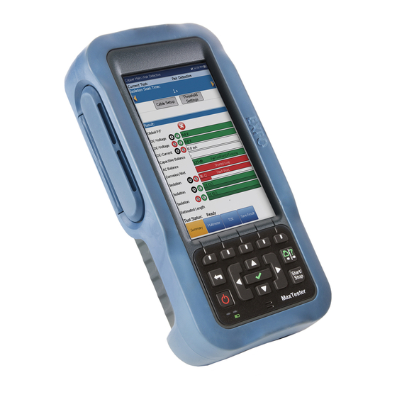
Introducing the MaxTester MAX-610 The MaxTester MAX-610 is a handheld device designed to qualify and troubleshoot the copper-loop plant by using pass/fail-driven automated functionalities. Product Description The MAX-610 Test Set case is an aluminum enclosure with rubber over mold, which makes it ideal for field use. Its display is a back-lit LCD featuring 480 x 800 resolution. -
Page 10: Typical Applications
Introducing the MaxTester MAX-610 Typical Applications Typical Applications Auto tests including POTS Auto Test Multimeter tests Noise tests including power influence, PSD, and attenuation analysis Frequency tests including balance, load coils, and locator tone Fault location tests including TDR and RFL ... - Page 11 Introducing the MaxTester MAX-610 Using the MAX-610 Right USB Client Port DC Power Door Front Power LED Battery LED Speaker MaxTester Copper Test...
- Page 12 Introducing the MaxTester MAX-610 Using the MAX-610 Back Screws Screws Battery Door Note: The MAX-610 enclosure may become warm during normal use. MAX-610...
-
Page 13: Cable Connections
Introducing the MaxTester MAX-610 Cable Connections Cable Connections The graphics below show the connectors on the MAX-610 device. Primary tip/A and Secondary tip/A and Ground ring/B connectors ring/B connectors terminal Note: When connecting a DSL cable to the WAN port, use the RJ-45 plug end of the cable provided with the unit. - Page 14 Introducing the MaxTester MAX-610 Cable Connections Secondary Tip/A wire of phone line Secondary Ring/B wire of phone line Shield of phone line Primary Tip/A wire of phone line Primary Ring/B wire of phone line MAX-610...
- Page 15 Introducing the MaxTester MAX-610 Cable Connections ARNING A 50 to 500 Vcc limited power source may be present on connector R/T/R1/T1 when the unit is testing isolation resistance. Use with caution. ARNING These connections are intended for the express purpose of electrical testing of common telephone line conductors, within the ranges specified in the Technical Specifications on page 265.
-
Page 16: Conventions
Introducing the MaxTester MAX-610 Conventions Conventions Before using the product described in this guide, you should understand the following conventions: ARNING Indicates a potentially hazardous situation which, if not avoided, could result in death or serious injury. Do not proceed unless you understand and meet the required conditions. -
Page 17: Safety Information
Safety Information ARNING The use of controls, adjustments and procedures other than those specified herein may result in exposure to hazardous situations or impair the protection provided by this unit. MPORTANT When you see the following symbol on your unit , make sure that you refer to the instructions provided in your user documentation. -
Page 18: Electrical Safety Information
When using the MaxTester while connected to the AC/DC adapter/charger, make sure you do not position the equipment so that it is difficult to disconnect the adapter/charger from the AC mains. ARNING Use only accessories that meet EXFO specifications. MAX-610... -
Page 19: Equipment Ratings
Safety Information Equipment Ratings Equipment Ratings Equipment Ratings Temperature Operation 0 °C to 40 °C (32 °F to 104 °F) Storage –40 °C to 70 °C (–40 °F to 158 °F) Relative humidity 95 % non-condensing unit ... -
Page 21: Getting Started With The Maxtester
Getting Started with the MaxTester Turning the Unit On/Off When you turn the unit on, you may use it immediately under normal conditions. When the unit is turned off, it keeps the following parameters in its internal memory: Setup including application settings, phone and cable books, and test ... -
Page 22: Using Menus And Keypad
Getting Started with the MaxTester Using Menus and Keypad To enter suspend mode: Press for about 2 seconds. The MaxTester will stay in suspend mode for 2 hours. After which it will automatically shutdown. This prevents complete battery discharge and ensures maximum battery performance. To perform a shutdown: Hold down for at least 4 seconds. -
Page 23: Keypad
Getting Started with the MaxTester Keypad Keypad Arrow keys Function keys Home/Help Back Start/Stop test Power Enter Power button on the lower left side of the unit is used to power the unit on and off. Arrow Keys navigate the screen to access and modify parameters. ... -
Page 25: Setting Up The Maxtester Max-610
Setting Up the MaxTester MAX-610 Home Home presents the main menu page which allows you to navigate between Copper Test and System Settings using the left/right arrow keys on the keypad. Press to bring up the sub-menu of the selected icon: Copper Test opens the Copper Main menu ... -
Page 26: System Settings
Setting Up the MaxTester MAX-610 System Settings System Settings System Settings presents a menu of items to setup the unit. Display & Language provides the setup for backlight, information on the title bar, and language choice. Date & Time sets the date and time and format. -
Page 27: Display And Language
Setting Up the MaxTester MAX-610 Display and Language Display and Language To fit your environment, you may adjust the LCD brightness, display the time and Active Sync, and change the display language. The values are kept in memory when you turn the unit off. -
Page 28: Date And Time
Setting Up the MaxTester MAX-610 Date and Time Date and Time When saving results, the unit also saves the corresponding Date and Time. You can enter the date according to the following formats: yyyy-mm-dd (default) dd-mm-yyyy mm-dd-yyyy ... -
Page 29: Power
Setting Up the MaxTester MAX-610 Power Power Battery Status The BATTERY Status pane indicates the current power level for the battery. Note: The battery level might not display after a system upgrade but will become available again after the next full charge. - Page 30 Setting Up the MaxTester MAX-610 Power Note: Setting the DC IN suspend timeout to the lowest value and not to Never ensures the unit enters suspend mode while the charger is connected. Battery charging time is quickest when the unit is in suspend mode.
- Page 31 Setting Up the MaxTester MAX-610 Power Aborted displays when the calibration procedure has been started but the DC plug was removed before the end. Idle displays after the next MaxTester cold boot. Gas Gauge Accuracy indicates the estimated battery gas gauge ...
-
Page 32: Software Options
Setting Up the MaxTester MAX-610 Software Options Software Options Copper Options This screen lists all the Copper Configured Options which are present on the unit. Possible options are as follow: FaultMapper Pair Detective 30 MHz Wideband Testing ... -
Page 33: Information
Setting Up the MaxTester MAX-610 Information Information About EXFO The About tab contains contact information should you require technical assistance. MAX-610 Information The Information tab displays information about the product, software, and memory installed on the device. The page also identifies hardware information. -
Page 34: Upload Setup
Setting Up the MaxTester MAX-610 Upload Setup Upload Setup Upload Enable The Upload Enable function allows you to upload your result files using one of the following upload methods: Wi-Fi allows you to upload files from the MaxTester to a Wi-Fi hotspot/router and is... - Page 35 Setting Up the MaxTester MAX-610 Upload Setup Ethernet is the default upload and if selected, displays ethernet icon in the top right-hand corner of the navigation bar. It identifies whether or not a connection is present displaying a green or yellow icon similar to the Wi-Fi symbol described above.
- Page 36 Setting Up the MaxTester MAX-610 Upload Setup FTP Setup The FTP Setup function allows you to configure the file transfer information using the following parameters: Address Format allows you to select the FTP server address type: IP Address ...
- Page 37 Setting Up the MaxTester MAX-610 Upload Setup To configure the setup options: 1. Press the up/down arrows to select the desired parameter. 2. Press the left/right arrow keys to view and select the options. 3. Press on a value to open a list box of options or the alphanumeric editor screen and use the navigation keys to scroll through.
- Page 38 Setting Up the MaxTester MAX-610 Upload Setup Select Other Network button opens a new page allowing you to search for a specific network. Find Networks button searches for available networks. To connect your MaxTester to a Wi-Fi network: 1.
- Page 39 Setting Up the MaxTester MAX-610 Upload Setup Select Network The Select Network page allows you to search for a specific Wi-Fi network. Network Name opens the alphanumeric editor screen allowing you to enter the name of the desired Wi-Fi network.
- Page 40 Setting Up the MaxTester MAX-610 Upload Setup Ethernet Setup The Ethernet Setup function allows you to configure the line and access modes, etc for an Ethernet connection, using the following parameters: Access Mode options are DHCP , Static, or PPPoE.
- Page 41 Setting Up the MaxTester MAX-610 Upload Setup The following parameters are available only when Access Mode is Static. IP Address is the address for the unit that is actively connected to your network or the internet at the time of login.
-
Page 43: Setting Up Copper Tests
Setting Up Copper Tests The MaxTester is designed to test basic twisted pair quality, identify and locate faults, and troubleshoot noise and signal issues. These measurements offer a quick and thorough method to determine if the cable is capable of supporting xDSL technology. In addition, it utilizes noise measurements, longitudinal balance tests, and power spectral density tests to assist in the installation, maintenance, and troubleshooting of copper cables. -
Page 44: Test Configuration
Setting Up Copper Tests Test Configuration Test Configuration Before performing copper tests, you can set up the software settings and values for the cables. The MaxTester allows you to save test parameters and threshold settings to different profiles and reuse them as needed. The Test Configuration menu provides the utilities to setup test parameters. - Page 45 Setting Up Copper Tests Test Configuration Copy to USB allows you to copy all profiles found in the internal memory to an external USB device. If the profile name already exists in the destination folder, you will prompted to overwrite existing profile(s).
- Page 46 Setting Up Copper Tests Test Configuration To save a profile, use one of the following function keys: Save allows you to save to the currently selected profile name. Save As opens the alphanumeric editor screen allowing you to enter a new name for the profile selected.
- Page 47 Test Configuration Profile Details Main Menu You can view any of your saved profiles on the MaxTester MAX-610 from the Profile Details menu by selecting the desired test icon. An asterisk "*" on the currently Selected Profile name indicates that modifications have been made to this profile in the Threshold Settings or parameters of a particular test.
- Page 48 Setting Up Copper Tests Test Configuration To navigate between the test profiles: 1. Press the up/down left/right arrow keys on the keypad to select an icon. 2. Press to confirm your selection. Noise Tests Profile Details The profile details Noise Tests main menu allows you to view the test threshold and parameters of the following tests: VF Noise...
- Page 49 Setting Up Copper Tests Test Configuration Frequency Tests Profile Details The profile details Frequency Tests main menu allows you to view the test threshold and parameters of the following tests: VF/AC Balance WB Balance WB Attenuation TX/RX Tone ...
- Page 50 Setting Up Copper Tests Test Configuration Delete Profile Delete Profile lists all profiles found on the internal memory except the default profile, which cannot be removed. Selected Profile displays the profile name in use. To delete a profile: 1. Press the up/down arrow keys to highlight the entry to be removed and press 2.
-
Page 51: Setup
Setting Up Copper Tests Setup Setup The Setup function allows you to set up parameters common to all tests. To access the Setup function: 1. On the Home pane, highlight Copper Test, then press 2. From the Copper Main page select Setup and press Setup presents a menu of items to setup copper tests. -
Page 52: Phone Book
Setting Up Copper Tests Phone Book Phone Book The Phone Book menu presents a selection of functions which allow you to manage the groups of phone numbers relevant to performing the copper tests. It can include a maximum of 50 groups of up to 3 individual entries each. - Page 53 Setting Up Copper Tests Phone Book Select Group/Entry The page lists entries by Group ID and Entry Name/Type. There is 1 group of 3 factory default entries which cannot be edited or deleted. The Phone Book can include a maximum of 50 groups. Group # in use displays the group number in use.
- Page 54 Setting Up Copper Tests Phone Book Type displays the following list of values: Milliwatt tone Drop battery Quiet line - (for additional line types) Enable displays either Yes or No. Accept function key validates and updates all the parameters of the ...
- Page 55 Setting Up Copper Tests Phone Book Add Group The Add Group page allows you to add a new group entry into the Phone Book using the following parameters for the currently highlighted Group ID. Group ID displays the group ID number. This ...
- Page 56 Setting Up Copper Tests Phone Book Clone Group The Clone Group page allows you to copy the details of an existing entry to a new group entry in the Phone Book. The page lists all entries by Group ID. The list can display a maximum of 50 entries. Group # In Use displays the Group ID number in use.
- Page 57 Setting Up Copper Tests Phone Book Delete Group The Delete Group page allows you to delete a group entry from the Phone Book. The page lists all entries by Group ID. Group # in Use displays the group number in use. To delete a group entry: 1.
- Page 58 Setting Up Copper Tests Phone Book Load Phone Book The Load Phone Book page allows you to import a phone book. The page displays the file name and date of the last phone book loaded. Only .csv files are supported. The Storage Location lists the load destinations: ...
- Page 59 Setting Up Copper Tests Phone Book Save Phone Book The Save Phone Book page allows you to save or export a phone book. Save File allows you to enter a file name of the current phone book to save. By default, the name is phone_book.csv.
-
Page 60: Dialer Function
Setting Up Copper Tests Dialer Function Dialer Function The Dialer function provides a dial-up path from the MAX-610 to another tester (or quiet termination or silent switchman) through a switched circuit network. DTMF (dual-tone multi-frequency) transmission is enabled via the phone keypad allowing you to place POTS calls. - Page 61 Setting Up Copper Tests Dialer Function Enter Number displays the telephone number entered or selected from the Recent Dialed Numbers list or Phone Book. Recent Dialed Numbers button opens a list of recently dialed numbers for selection. Select From Phone Book button allows you to select a number from ...
- Page 62 Setting Up Copper Tests Dialer Function Enter Number The Enter Number box is where you enter the phone number you wish to dial. To enter a phone number: 1. Press any of the buttons on the key pad by using the navigation keys on the unit and pressing The selected numbers are entered in the text box.
- Page 63 Setting Up Copper Tests Dialer Function Recent Dialed Numbers The Select Number page lists a maximum of 8 recently dialed telephone numbers which you can select to make your call. To select a recently dialed number: 1. Use the up/down arrow keys to select an entry. 2.
- Page 64 Setting Up Copper Tests Dialer Function Add to Phone Book The Add Group page allows you to add a new group entry into the Phone Book using the following parameters for the currently highlighted Group ID. Group ID displays the group ID number. This ...
-
Page 65: Cable Book
Setting Up Copper Tests Cable Book Cable Book The Cable Book menu allows you to select, add, clone, and delete a cable, as well as modify its details, such as: Select Cable Cable Details Add Cable Clone Cable ... - Page 66 Setting Up Copper Tests Cable Book Cable Details The Cable Details page allows you to view the cable parameter details of the currently highlighted cable entry. Cable ID displays the cable ID number. Cable Name is the name of the cable in the Cable ...
- Page 67 Setting Up Copper Tests Cable Book To view and modify the cable details: 1. Press the up/down arrow keys to highlight the desired parameter. 2. Press the left/right arrow keys to view and select the options. 3. Press on a value to open a list box of options or the alphanumeric editor screen and use the navigation keys to scroll through.
- Page 68 Setting Up Copper Tests Cable Book Attenuation @ 300 kHz allows you to specify a value for the reduction in signal strength or insertion loss of the cable. VOP allows you to set the velocity of propagation for the cable as a ...
- Page 69 Setting Up Copper Tests Cable Book Clone Cable The Clone Cable page allows you to copy the cable details of an existing entry to a new cable entry in the Cable Book. The page lists all entries by Cable ID and Cable Name.
- Page 70 Setting Up Copper Tests Cable Book Delete Cable The Delete Cable page allows you to delete a cable entry from the Cable Book. The page lists all entries, excluding the 10 factory default cable entries, by Cable ID and Cable Name. Cable # In Use displays the Cable ID number in use.
-
Page 71: Application Settings
Setting Up Copper Tests Application Settings Application Settings Before executing the copper tests, set up the software settings and values for the cables. The MAX-610 allows you to save standard parameter settings to different profiles and reuse them as needed. To access Application Settings: From the Home pane, select Copper Test, then Setup, and Application Settings. - Page 72 Setting Up Copper Tests Application Settings Test Startup Mode lists the test startup type: Auto (default) automatically starts a test when you select the respective icon from the test sub-menu pane and press Manual requires that you press Start/Stop on the MaxTester keypad ...
- Page 73 Setting Up Copper Tests Application Settings Standard The Standard tab allows you to set unit parameter values composed of the following: Standard Selection Standard allows you to specify if the copper tests should conform to the ITU (International Telecommunications) or ANSI (American National Standards Institute) standard.
- Page 74 Setting Up Copper Tests Application Settings Label Customization Connection lists the type of cable connection: T-R-G or A-B-E. Test Parameters Preset Power Line Frequency lists the frequency value of the power line. Termination Impedance lists the values for the impedance of the ...
- Page 75 Setting Up Copper Tests Application Settings Identification The Identification tab allows you to preset values to identify each single and auto test result file when saving them. The parameters are as follow: User Name/User ID allow you to enter up to 25 ...
- Page 76 Setting Up Copper Tests Application Settings To select the parameter values: 1. Press the up/down arrow keys to highlight the desired parameter. 2. Press the left/right arrow keys to view and select the options. 3. Press on a value to open a list box of options or the alphanumeric editor screen and use the navigation keys to scroll through.
- Page 77 Setting Up Copper Tests Application Settings File Name The File Name tab sets up the standard configuration for automatically naming a result file. You can only Enable/Disable the entries. All enabled entries are considered for file name generation. File Name Preview displays a preview of the file ...
- Page 78 Setting Up Copper Tests Application Settings Change Order Change Order page allows you to change the order of the entries in the file name. To change the order: 1. Press to get into the list. 2. Use the up/down arrow keys to select the desired entry.
- Page 79 Setting Up Copper Tests Application Settings Buzzer The Buzzer tab allows you to configure values for the buzzer settings. However, due to the risk of electrical shocks, the MaxTester detects high voltages on any pair of leads without user intervention. Buzzer Threshold Voltage allows you to ...
-
Page 80: Test Lead Compensation
Setting Up Copper Tests Test Lead Compensation Test Lead Compensation Test lead compensation is required for some of the copper tests so as not to affect data accuracy, since test lead characteristics have some impact on copper test results (mainly resistance, capacitance, and TDR tests). -
Page 81: Fed Setup
Setting Up Copper Tests FED Setup FED Setup FED Setup is an option enabled feature that implements Teletech TS125 Remote FED (far end device) detection and allows you to predetermine and place the FED in one of the following states: Pass Through/Exchange Connect ... - Page 82 Setting Up Copper Tests FED Setup 2. For Open, set the FED so that the T-R/A-B wires connected to the customer side of the FED are open circuited. 3. For T-R-G/A-B-E Shorted, set the FED so that T-R-G/A-B-E are all short circuited (connected to each other) at the customer side of the FED.
- Page 83 Setting Up Copper Tests FED Setup The FED Setup tab displays the following parameters: FED sets the default FED States for the following tests to Enabled or Disabled, and is saved as part of the profile: Multimeter Noise ...
- Page 84 Setting Up Copper Tests FED Setup Note: For all FED States other than Pass Through/Exchange Connect, the Dialer tab is disabled. If the dialer is already running before the test starts, the dialer will be stopped on entry of the test with a message saying Dialer cannot be used, hence dialer will be stopped.
- Page 85 Setting Up Copper Tests FED Setup Multimeter The Multimeter tab lists the default FED States set for all multimeter tests. Noise The Noise tab lists the default FED States set for all noise tests. MaxTester Copper Test...
- Page 86 Setting Up Copper Tests FED Setup Frequency The Frequency tab lists the default FED States set for all frequency tests. Other The Other tab displays the default FED States set for all other tests such as TDR and RFL Single/Separate Good Pair.
-
Page 87: Saving Results
Setting Up Copper Tests Saving Results Saving Results Save Result You can save a snapshot of test results into a result file during or after a test performed with the MAX-610. Each copper test includes a Save Result tab to do so. The tab allows you to save your test results to an internal memory file or export results to an HTML, MHTML, or XML report using a USB key. - Page 88 Setting Up Copper Tests Saving Results Save Result Select Result File button displays a list of existing file names where you can save your results. Result File Storage Location gives you the option of storing results either in the MaxTester internal memory or USB device. The default selection comes from Application Settings/General tab.
- Page 89 Setting Up Copper Tests Saving Results To set parameter values and save results: 1. Press the left/right and up/down arrow keys to highlight the desired parameter. 2. Press to display the list or select the value. 3. Press the up/down arrow key to highlight the desired value. 4.
-
Page 91: Reading Saved Copper Test Results
Reading Saved Copper Test Results Read/Upload Result You can view or export any of your saved results with the MaxTester Copper Test, by highlighting the Read/Upload Result icon from the Copper Main pane and pressing Results Summary The Results Summary page allows you to select a File Name and view the results of files previously saved. -
Page 92: Read Result Menu
Reading Saved Copper Test Results Read Result Menu Read Result Menu The Read Result menu allows you to view saved test results with the following details: Summary displays general information and parameters of the test. Result Details displays measured results for each ... - Page 93 Reading Saved Copper Test Results Read Result Menu Summary The results Summary page displays pass/fail status, general and identification information, along with comments, for the test. General Information displays read-only information pertaining to the test result. Result File Name ...
- Page 94 Reading Saved Copper Test Results Read Result Menu Function keys: Save keeps any current changes with the current file name. Save As saves the current changes under a different file name that you can configure in the editor screen. Don’t Save does not save any changes and closes the page.
- Page 95 Reading Saved Copper Test Results Read Result Menu Result Details The Results Details page allows you to view measured results for each lead combination and cable parameters of the selected test. Profile Details The Profile Details page displays read-only test thresholds and/or parameters information about the setup of the selected test.
- Page 96 Reading Saved Copper Test Results Read Result Menu Phone Book The Phone Book page summarizes the Phone Book details when loading a results file. It contains information about group entries such as group ID, name, phone numbers, and tags. If the dialer was not used during the test, the Phone Book icon will not appear as part of the Read Result menu page.
-
Page 97: Upload
Reading Saved Copper Test Results Upload Upload The Upload page allows you to upload the saved results of User Auto tests only to an FTP site or a USB memory stick. Select a File Name or All files previously saved. Files are uploaded via the selected method (Wi-Fi or Ethernet) as shown by the corresponding icon in the top right-hand corner of the navigation bar. -
Page 98: Export
Reading Saved Copper Test Results Export Export The Export page allows you to select a File Name or All files previously saved and export the results in a selected Report Format. Storage Location gives you the option of exporting your results to either the MT internal memory or USB device. - Page 99 Reading Saved Copper Test Results Export 8. Press the left/right arrow keys to select the desired format 9. Press to display the list and select the value. 10. Press the down arrow key to press the Export button. MaxTester Copper Test...
-
Page 101: Multimeter Tests
Multimeter Tests The purpose of the multimeter tests function is to detect AC/DC voltages and currents, and measure resistance and capacitance in a loop. These tests allow you to make basic electrical safety checks (AC volts), check for crossed or coupled battery voltages, assess basic loop continuity and quality with resistance measurements, and measure total electrical length with capacitance. -
Page 102: Voltage
Multimeter Tests Voltage Voltage The Voltage test detects AC RMS and DC voltages in the line and allows you to measure AC/DC voltages and Frequency on A/B/E or T/R/G depending on the selected Standard in Setup/Application Settings. Snapshot The voltage Snapshot shows measured volts for each lead combination. - Page 103 Multimeter Tests Voltage To select the parameter values: 1. Press the up/down arrow keys to highlight the desired parameter. 2. Press the left/right arrow keys to view and select the options. 3. Press on a value to open a list box of options. 4.
- Page 104 Multimeter Tests Voltage Continuous AC Page The Continuous AC function measures each pair, displaying and updating results in real time, until you stop the test. The last valid results then remain displayed. Continuous AC and Continuous DC are run synchronously. Press Start/Stop on the keypad to run the test.
- Page 105 Multimeter Tests Voltage To select the parameter values: 1. Press the up/down arrow keys to highlight the desired parameter. 2. Press the left/right arrow keys to view and select the options. 3. Press on a value to open a list box of options. 4.
- Page 106 Multimeter Tests Voltage Result displays a snapshot of the pass/fail status and volts for each continuous DC pair. Test Status displays the current state of measurement or an error message. To select the parameter values: 1. Press the up/down arrow keys to highlight the desired parameter. 2.
-
Page 107: Current
Multimeter Tests Current Current The Current test allows you to measure the AC/DC currents and frequency in the loop. Snapshot The current Snapshot shows measured AC/DC results for each lead combination. The parameters are as follow: Current Group is the current test group name, for ... - Page 108 Multimeter Tests Current To select the parameter values: 1. Press the up/down arrow keys to highlight the desired parameter. 2. Press the left/right arrow keys to view and select the options. 3. Press on a value to open a list box of options. 4.
- Page 109 Multimeter Tests Current Continuous AC Page The Continuous AC function measures each pair, displaying and updating results in real time, until you stop the test. The last valid results then remain displayed. Continuous AC and Continuous DC are run synchronously. Press Start/Stop on the keypad to run the test.
- Page 110 Multimeter Tests Current To select the parameter values: 1. Press the up/down arrow keys to highlight the desired parameter. 2. Press the left/right arrow keys to view and select the options. 3. Press on a value to open a list box of options. 4.
- Page 111 Multimeter Tests Current Result displays a snapshot of the pass/fail status and DC current results for each selected wire pair. Test Status displays the current state of measurement or an error message. To select the parameter values: 1. Press the up/down arrow keys to highlight the desired parameter. 2.
-
Page 112: Resistance
Multimeter Tests Resistance Resistance The Resistance test, also know as shorts, allows you to measure the current resistance value and cable length for line under test. Snapshot The resistance Snapshot shows measured current resistance values and cable lengths for each lead combination. - Page 113 Multimeter Tests Resistance To select the parameter values: 1. Press the up/down arrow keys to highlight the desired parameter. 2. Press the left/right arrow keys to view and select the options. 3. Press on a value to open a list box of options. 4.
- Page 114 Multimeter Tests Resistance Continuous The Continuous function measures each pair, displaying and updating results in real time, until you stop the test. The last valid results then remain displayed. Current Group is the current test group name, for example Multimeter. Current Test displays the test being measured.
-
Page 115: Resistive Balance
Multimeter Tests Resistive Balance To select the parameter values: 1. Press the up/down arrow keys to highlight the desired parameter. 2. Press the left/right arrow keys to view and select the options. 3. Press on a value to open a list box of options or the alphanumeric editor screen and use the navigation keys to scroll through. - Page 116 Multimeter Tests Resistive Balance Threshold Settings button opens a new page that allows you to set the resistive balance thresholds. Test Status displays the current state of measurement or an error message. To select the parameter values: 1. Press the up/down arrow keys to highlight the desired parameter. 2.
- Page 117 Multimeter Tests Resistive Balance Result Details The Results Details read-only page displays the Resistance results for each lead combination and the pass/fail status for Resistive Balance in and %. Ω Profile Details The Profile Details page displays read-only Resistive Balance thresholds. Profile Name is the file name of the selected ...
-
Page 118: Isolation
Multimeter Tests Isolation Isolation The Isolation test, also known as leakage, allows you to run a resistance test over a period of time to look for high-resistive faults. The test, also referred to as a stress or leakage test, shows how cable resistance may be lowered by applying a high voltage to the pair under test. - Page 119 Multimeter Tests Isolation Result displays a snapshot of the pass/fail status, Resistance and a Soak Counter for each selected wire pair. When running the test, the counter counts to the selected Soak Time by the second, for the wire pair(s) under test.
- Page 120 Multimeter Tests Isolation 3. Press on a value to open a list box of options or the alphanumeric editor screen and use the navigation keys to scroll through. 4. Press to confirm the value. Continuous The Continuous function measures each pair, displaying and updating results in real time, until you stop the test.
- Page 121 Multimeter Tests Isolation Result displays a snapshot of the pass/fail status, Resistance and a Soak Counter for each selected wire pair. While running the test, the counter displays the soak period by the second, for the wire pair(s) under test. Test Status displays the current state of measurement or an error ...
-
Page 122: Capacitance/Opens
Multimeter Tests Capacitance/Opens Capacitance/Opens The Capacitance/Opens test measures the capacitance of the loop and calculates length. Capacitive balance is also measured when all pairs are selected. Snapshot The capacitance/opens Snapshot shows measured Capacitance values and Length for each lead combination. The parameters are as follow: Current Group is the current test group name, for ... - Page 123 Multimeter Tests Capacitance/Opens Capacitance T/R to GND displays the capacitance value from Tip or Ring to Ground, in nF/mi ranging from 10.0 to 500.0. Threshold Settings button opens a new page that allows you to set the capacitance/opens threshold for the test. Result displays a snapshot of the pass/fail status, Capacitance and ...
- Page 124 Multimeter Tests Capacitance/Opens Note: The accuracy of the 2 Terminal Capacitance Measurement is impacted by the use of the FED, and the 3 Terminal method is recommended to be used instead. Selected Pair allows you to select All Pairs or a single wire pair for ...
- Page 125 Multimeter Tests Capacitance/Opens Capacitance/Opens Threshold Settings The Threshold Settings page allows you to set the Capacitive Balance Threshold parameters for the test between 0 and 100 %. Type is the threshold limit for each pair: either Maximum or Minimum. Enabled is a flag to use the current threshold: ...
-
Page 126: Station Ground
Multimeter Tests Station Ground Station Ground The Station Ground test measures and displays the resistance value and pass/fail status of the ground resistance between the MaxTester and the CO (Central Office). The test uses Tip (A), Ring (B), and Ground (Earth) leads and measures isolation resistance between the wires and to ground. - Page 127 Multimeter Tests Station Ground The Confirmation window is prompted before every Station Ground test is started if you selected Yes for the Show hookup diagram. You can select No to hide the diagram next time you run the test. However, you can check the connection diagram at any time by pressing the Hookup Diagram button.
- Page 128 Multimeter Tests Station Ground Threshold Settings The Test Thresholds page allows you to set the threshold values for the Ground Resistance. Type is the threshold limit: either Maximum or Minimum. Enabled is a flag to use the current threshold: ...
-
Page 129: Stressed Balance
Multimeter Tests Stressed Balance Stressed Balance The Stressed Balance is an option enabled test that continuously generates high voltage to the cable pair under test. The high voltage stresses the leads in order to reveal imbalances that may otherwise be hidden with the normal VF Balance test. - Page 130 Multimeter Tests Stressed Balance Threshold Settings The Threshold Settings page allows you to set the Good/Marginal Balance threshold values for the Stressed Balance test. Type is the threshold limit and is fixed to Maximum. Enabled is a flag to use the current threshold: ...
- Page 131 Multimeter Tests Stressed Balance Result Details The Result Details read-only page displays the Stressed Balance results and the pass/fail status. Test Group is the overall test group of the selected saved results file, for example Multimeter. Test Identification is the test type of the group, for ...
-
Page 133: Smartr™ Features
SmartR™ Features SmartR features, consisting of Pair Detective and FaultMapper, allow you to determine the condition of the line under test, as well as identify and locate a variety of common circuit faults. Pair Detective The Pair Detective test consists of a series of 10 consecutive individual tests and applies a high voltage to the line during isolation testing. - Page 134 SmartR™ Features Pair Detective Summary The Summary page displays a summary of the pass/fail status, DC-Voltage/Current and Isolation for each selected inactive wire pair, as well as other detailed results of the Pair Detective test. Isolation results also display a five-level indicator of the measured isolation.
- Page 135 SmartR™ Features Pair Detective Pair Detective Cable Setup The Cable Setup page allows you to set Cable Parameters for the Pair Detective test. Cable Type allows you to select a cable entry (with its associated parameters) from the current Cable Book, to use for testing.
- Page 136 SmartR™ Features Pair Detective Pair Detective Threshold Settings The Threshold Settings page allows you to set the Pair Detective Threshold Settings as follow: Foreign DC Voltage sets the maximum foreign DC voltage value. POTS DC Voltage sets the minimum working ...
- Page 137 SmartR™ Features Pair Detective Multimeter The Pair Detective Multimeter page displays read-only results and the P/F (pass/fail) status for the following tests: DC Voltage displays the volts for each DC Pair. DC Current displays the DC current results for T-R ...
- Page 138 SmartR™ Features Pair Detective The previous 2 parameters have 2 modes of operation: Auto is the default mode upon loading the test page. TDR automatically optimizes the test parameters and scans each band individually looking for one Largest Event in each band (if any). Range and Gain are updated to reflect optimized TDR settings.
- Page 139 SmartR™ Features Pair Detective Pan - use left/right arrow keys to pan the x-axis and the up/down arrow keys to pan the y-axis. 1:1 resets the x-axis and y-axis limits to full scale. Return To Test removes these function keys and displays the ...
- Page 140 SmartR™ Features Pair Detective Cable Setup The Cable Setup page allows you to set Cable Parameters for the TDR test. Cable Type allows you to select a cable entry (with its associated parameters) from the current Cable Book, to use for testing. The selection is not saved when leaving the test.
-
Page 141: Pair Detective Result Details
SmartR™ Features Pair Detective Result Details Pair Detective Result Details Summary The read-only Summary page displays the cable parameters and detailed results saved from running the Pair Detective test. Test Identification is the test type of the group, for example Pair Detective. Cable Type is the cable entry (with its ... - Page 142 SmartR™ Features Pair Detective Result Details Multimeter The read-only Multimeter page displays detailed results saved from running the Pair Detective test. Please refer to Multimeter on page 129 for more information. MAX-610...
-
Page 143: Faultmapper
SmartR™ Features FaultMapper FaultMapper The FaultMapper test allows you to locate and identify service-affecting line faults using TDR (time domain reflectometry) and RFL (resistance fault locator) technology. This test is useful in locating bridged taps, shorts, grounds, and opens. Current Test displays the test being measured. ... - Page 144 SmartR™ Features FaultMapper Open and the distance to Open is displayed and represented using X in the graph. Test Status displays the current state of measurement or an error message. To select the parameter values: 1. Press the up/down arrow keys to highlight the desired parameter. 2.
- Page 145 SmartR™ Features FaultMapper Attenuation @ 300 kHz read-only entry is a value for the reduction in signal strength or insertion loss of the cable. Velocity of Propagation read-only entry is the velocity of propagation for the cable as a ratio of the speed of light. Resistance read-only entry is a value for the resistance constant of the ...
- Page 146 SmartR™ Features FaultMapper FaultMapper Result Details The Result Details read-only page displays the test results in text and graphical format. Test Identification is the name of the test, for example FaultMapper. Cable Setup button opens a new page displaying ...
- Page 147 SmartR™ Features FaultMapper Result Details Cable Setup The Cable Setup page in the Result Details allows you to view the Cable Parameters set for the FaultMapper test. Cable Type is the cable entry (with its associated parameters) from the current Cable Book, used for testing.
- Page 148 SmartR™ Features FaultMapper FaultMapper Profile Details The Profile Details page displays read-only FaultMapper Test Parameters. Profile Name is the file name of the selected saved results. Test Identification is the test type of the group, for example FaultMapper. MAX-610...
-
Page 149: Noise Tests
Noise Tests The purpose of the noise tests is to perform VF (voice frequency)/WB (wideband) noise and level measurements. Note: The 30 MHz Wideband Testing software option is required for the WB tests to be available. To access noise tests: From the Copper Main pane, highlight Noise Tests and press to open the menu. -
Page 150: Vf Noise
Noise Tests VF Noise VF Noise The VF Noise test allows you to measure the amount of unwanted or disturbing energy introduced into a loop from man-made and natural sources. Detection The Detection function displays and updates results in real time, until you stop the test. The last valid results then remain displayed. - Page 151 Noise Tests VF Noise To select the parameter values: 1. Press the up/down arrow keys to highlight the desired parameter. 2. Press the left/right arrow keys to view and select the options. 3. Press on a value to open a list box of options. 4.
- Page 152 Noise Tests VF Noise Result Details The Results Details read-only page displays the VF Noise value and the pass/fail status. MAX-610...
-
Page 153: Power Influence
Noise Tests Power Influence Power Influence The Power Influence test allows you to view the effects of interference from a 50 Hz or 60 Hz power source (AC mains) on the circuit under test. The results of the power influence test are also in graphical form. Detection The Detection function displays and updates results in real time, until you stop the test. - Page 154 Noise Tests Power Influence Zoom references the middle of the x/y axis and not the cursor position. Press the arrow keys as follows: Right = x-axis zoom in. Left = x-axis zoom out. Up = y-axis zoom in. Down = y-axis zoom out. Pan - use left/right arrow keys to pan the x-axis and the up/down ...
- Page 155 Noise Tests Power Influence Power Influence Threshold Settings The Threshold Settings page allows you to set the Threshold Power Influence values for the test. Type is the threshold limit: either Maximum or Minimum. Enabled is a flag to use the current threshold: ...
-
Page 156: Vf Impulse Noise
Noise Tests VF Impulse Noise VF Impulse Noise The VF Impulse Noise test allows you to measure voice frequency impulse noise on the circuit under test. Count The Count function displays and updates results in real time, for the length of time set in Test Duration or less if you stop the test. - Page 157 Noise Tests VF Impulse Noise To select the parameter values: 1. Press the up/down arrow keys to highlight the desired parameter. 2. Press the left/right arrow keys to view and select the options. 3. Press on a value to open a list box of options. 4.
- Page 158 Noise Tests VF Impulse Noise VF Impulse Noise Threshold Settings The Threshold Settings page allows you to set the VF Impulse Noise Threshold values for the test. Low Counter Power Detection Level defines the low threshold limits for the impulse noise test. Power Separation defines the level difference ...
- Page 159 Noise Tests VF Impulse Noise Result Details The Results Details read-only page displays the High, Mid, Low VF Impulse Noise Count and Detection Level values, and the pass/fail status of the Mid level. MaxTester Copper Test...
-
Page 160: Wb Psd Noise
Noise Tests WB PSD Noise WB PSD Noise The wideband power spectral density (PSD) noise test measures the noise energy at a point in a noise spectrum. It is expressed as power per hertz at a point in a noise spectrum. The PSD page allows you to configure the parameters for the wideband PSD noise test and view the results in either Portrait or Landscape Mode. - Page 161 Noise Tests WB PSD Noise Cursor - press the left/right arrow keys to decrease/increase the values by moving the cursor. Press and hold the left/right arrow keys to accelerate the cursor. Press to recall the cursor and place it in the middle of the current x-axis limits. Zoom references the middle of the x/y axis and not the cursor ...
- Page 162 Noise Tests WB PSD Noise Landscape Mode function key allows you to view the test results in landscape mode. Rotating the unit clockwise or counter-clockwise and having the keyboard on the right or left is dependent on your preferred Landscape Mode Settings configured in Application Settings/General.
- Page 163 Noise Tests WB PSD Noise To select the parameter values in Portrait or Landscape modes: 1. Press the up/down arrow keys to highlight the desired parameter. 2. Press the left/right arrow keys to view, select the options, or increase/decrease values. 3.
- Page 164 Noise Tests WB PSD Noise Result Details The Results Details read-only page displays the WB PSD Noise test results, in text and graphical format, and can be viewed in portrait and landscape modes. You can maneuver the graph as follows: Cursor - press the left/right arrow keys to ...
-
Page 165: Wb Impulse Noise
Noise Tests WB Impulse Noise WB Impulse Noise The wideband impulse noise test allows you to measure impulse noise on the circuit under test. Count The Count function displays and updates results in real time, for the length of time set in Test Duration or less if you stop the test. - Page 166 Noise Tests WB Impulse Noise Result displays the Count, Detection Level, Elapsed Time, and pass/fail status which is periodically refreshed, until you stop the test. Test Status displays the current state of measurement or an error message. To select the parameter values: 1.
- Page 167 Noise Tests WB Impulse Noise WB Impulse Noise Threshold Settings The Threshold Settings page allows you to set the WB Impulse Noise Threshold values for the test. Power Detection Level defines the threshold limits. Counter allows you to set the threshold value for ...
- Page 168 Noise Tests WB Impulse Noise Result Details The Results Details read-only page displays the WB Impulse Noise Count, Detection Level, and pass/fail status. Profile Details The WB Impulse Noise Profile Details read-only page displays the test thresholds and parameters along with the Impulse Separation Time value. MAX-610...
-
Page 169: Next
Noise Tests NEXT NEXT The NEXT test measures the Near End Crosstalk (NEXT) between 2 pairs of cables. The test transmits a signal on the T/A - R/B pair, and measures the received crosstalk on T1/A1 - R1/B1 pair. Spot Spot is a continuous mode of operation measuring the crosstalk for a specific frequency selected by you, similar to the method used by the Send Tone test. - Page 170 Noise Tests NEXT Hookup Diagram button opens a Confirmation page displaying how to connect your cables at the beginning of the test. When FED is Enabled on the FED Setup page, both the T-R/A-B and T1-R1/A1-B1 pairs will be terminated at the FED. The hookup diagram uses graphic and textual components.
- Page 171 Noise Tests NEXT However, you can check the connection diagram at any time by pressing the Hookup Diagram button. In this case, the test does not start when you press the Ok button to close the Confirmation window. Threshold Settings button opens a new page that allows you to set the ...
- Page 172 Noise Tests NEXT To select the Spot parameter values: 1. Press the up/down arrow keys to highlight the desired parameter. 2. Press the left/right arrow keys to view and select the options. 3. Press on a value to open a list box of options or the alphanumeric editor screen and use the navigation keys to scroll through.
- Page 173 Noise Tests NEXT Spot Result Details The Spot Results Details read-only page displays the saved pass/fail status, NEXT and Frequency (TX) values. MaxTester Copper Test...
- Page 174 Noise Tests NEXT Spectrum Spectrum is a snapshot mode of operation similar to WB Attenuation. The test makes one measurement of the crosstalk for the selected bandwidth, and then stops. Current Group is the current test group name, for example Noise Tests.
- Page 175 Noise Tests NEXT Proceed button closes the hookup diagram prompt and starts the test. Cancel button closes the hookup diagram prompt only. The Confirmation window is prompted before every NEXT test is started if you selected Yes for the Show hookup diagram. You can select No to hide the diagram next time you run the test.
- Page 176 Noise Tests NEXT Threshold Settings button opens a new page that allows you to set the NEXT Spectrum Threshold. Select Graph button changes to Graph Selected when pressed and opens a new selection of function keys which allow you to maneuver the graph as follows: Cursor - press the left/right arrow keys to decrease/increase the ...
- Page 177 Noise Tests NEXT To select the parameter values: 1. Press the up/down arrow keys to highlight the desired parameter. 2. Press the left/right arrow keys to view and select the options. 3. Press on a value to open a list box of options. 4.
- Page 178 Noise Tests NEXT Spectrum Result Details The Spectrum Results Details read-only page displays the pass/fail status and test results in graphical format. Test Group is the overall test group of the selected saved results file, for example Noise Tests. Test Identification is the test type of the group, for ...
- Page 179 Noise Tests NEXT NEXT Results Profile Details The NEXT Profile Details page displays detailed read-only test thresholds and parameters for both Spot and Spectrum modes. Profile Name is the file name of the selected saved results. Test Group is the overall test group of the ...
-
Page 181: 10 Frequency Tests
10 Frequency Tests The purpose of the frequency tests is to perform VF (voice frequency) and WB (wide band) level measurements, calculate the reduction of signal strength during transmission, measure the balance of a circuit, count and detect the presence of load coils. To access frequency tests: From the Copper Main pane, highlight Frequency Tests and press... -
Page 182: Vf/Ac Balance
Frequency Tests VF/AC Balance VF/AC Balance The VF/AC Balance test allows you to check that the VF longitudinal balance ratio for the twisted pair complies with applicable standards so as to reduce the effects of common-mode voltage to ground. The test is a measurement of how much the T/A leg is like the R/B leg in electrical characteristics, measured by how much noise the line can mitigate (in dB). - Page 183 Frequency Tests VF/AC Balance Note: The selected Standard in Setup/Application Settings determines the name of the frequency test - ANSI: VF Balance, ITU: AC Balance. To select the parameter values: 1. Press the up/down arrow keys to highlight the desired parameter. 2.
- Page 184 Frequency Tests VF/AC Balance Active Result Details The Active Results Details read-only page displays the VF/AC Balance value and the pass/fail status. Passive The Passive function computes the passive balance as the difference between Power Influence and VF Noise, displaying and updating results in real time, until you stop the test.
- Page 185 Frequency Tests VF/AC Balance Result displays the Passive pass/fail status, Power Influence, VF Noise, and VF/AC Balance values. Test Status displays the current state of measurement or an error message. Note: The selected Standard in Setup/Application Settings determines the name of the frequency test - ANSI: VF Balance, ITU: AC Balance.
- Page 186 Frequency Tests VF/AC Balance VF/AC Balance Passive Threshold Settings The Threshold Settings page allows you to set the Passive VF/AC Balance Threshold values for the test. VF/AC Balance sets the passive balance threshold. Type is the threshold limit: either Maximum or ...
- Page 187 Frequency Tests VF/AC Balance Passive Result Details The Passive Results Details read-only page displays the Passive pass/fail status, Power Influence, VF Noise, and VF/AC Balance values. MaxTester Copper Test...
-
Page 188: Wb Balance
Frequency Tests WB Balance WB Balance The wideband balance test ensures that the balance ratio for the twisted pair complies with applicable standards so as to reduce the effects of common-mode voltage to ground. The better the balance of the cable pair, the higher the dB reading.The test measures the WB balance at fixed and periodic frequencies dependent on the selected bandwidth. - Page 189 Frequency Tests WB Balance Cursor - press the left/right arrow keys to decrease/increase the values by moving the cursor. Press and hold the left/right arrow keys to accelerate the cursor. Press to recall the cursor and place it in the middle of the current x-axis limits. Zoom references the middle of the x/y axis and not the cursor ...
- Page 190 Frequency Tests WB Balance Landscape Mode function key allows you to view the test results in landscape mode. Rotating the unit clockwise or counter-clockwise and having the keyboard on the right or left is dependent on your preferred Landscape Mode Settings configured in Application Settings/General.
- Page 191 Frequency Tests WB Balance To select the parameter values in Portrait or Landscape modes: 1. Press the up/down arrow keys to highlight the desired parameter. 2. Press the left/right arrow keys to view and select the options. 3. Press on a value to open a list box of options. 4.
- Page 192 Frequency Tests WB Balance Result Details The Results Details displays a graph of the Marginal and Good wideband balance results, and pass/fail status. Results can be viewed in portrait and landscape modes. You can maneuver the graph as follows: Cursor - press the left/right arrow keys to ...
-
Page 193: Wb Attenuation
Frequency Tests WB Attenuation WB Attenuation Attenuation The WB (wideband) single-ended attenuation test allows you to calculate the dissipation of power of a transmitted signal as it travels over the copper line. This test is performed from one end of the cable and does not require a remote second device. - Page 194 Frequency Tests WB Attenuation Zoom references the middle of the x/y axis and not the cursor position. Press the arrow keys as follows: Right = x-axis zoom in. Left = x-axis zoom out. Up = y-axis zoom in. Down = y-axis zoom out. Pan - use left/right arrow keys to pan the x-axis and the up/down ...
- Page 195 Frequency Tests WB Attenuation WB Attenuation Threshold Settings The Threshold Settings page allows you to set the WB Attenuation threshold values for the test. Attenuation sets up the good attenuation threshold parameters. Type is the threshold limit: either Maximum or ...
- Page 196 Frequency Tests WB Attenuation Cable Setup The Cable Setup page allows you to set the Cable Type and Cable Temperature for the WB Attenuation test. All other Cable Parameters are read only and correspond to the current cable book entry as selected in Setup/Cable Book/Cable Details page.
- Page 197 Frequency Tests WB Attenuation To select the parameter values: 1. Press the up/down arrow keys to highlight the desired parameter. 2. Press the left/right arrow keys to view and select the options. 3. Press on a value to open a list box of options or the alphanumeric editor screen and use the navigation keys to scroll through.
- Page 198 Frequency Tests WB Attenuation Select Graph button changes to Graph Selected when pressed and opens a new selection of function keys which allow you to maneuver the graph as follows: Cursor - press the left/right arrow keys to decrease/increase the ...
- Page 199 Frequency Tests WB Attenuation Result Details Cable Setup The Cable Setup page in the Result Details allows you to view the Cable Parameters set for the WB Attenuation test. Cable Type is the cable entry (with its associated parameters) from the current Cable Book, used for testing.
-
Page 200: Load Coils
Frequency Tests Load Coils Load Coils The Load Coils test allows you to detect the presence of load coils, which are detrimental to the use of DSL technologies on the line. If a load coil is detected, use the time domain reflectometry (TDR) test to quickly locate and remove it from the cable. - Page 201 Frequency Tests Load Coils Select Graph button changes to Graph Selected when pressed and opens a new selection of function keys which allow you to maneuver the graph as follows: Cursor - press the left/right arrow keys to decrease/increase the ...
- Page 202 Frequency Tests Load Coils The Load Coils TDR function provides a shortcut to the TDR test. A dialogue box opens, warning that you are about to leave the Load Coils test. TDR results captured while running Load Coils will be available upon loading TDR.
-
Page 203: Locator Tone
Frequency Tests Locator Tone Locator Tone When Locator Tone is selected from the Frequency Tests menu, a 577 Hz signal and a 983 Hz signal are sent separately for 200 ms each. The sequence of this tone is repeated continuously until you stop the test. Sinusoidal waveform is used to generate these signals. - Page 204 Frequency Tests Locator Tone To select the parameter values: 1. Press the up/down arrow keys to highlight the desired parameter. 2. Press the left/right arrow keys to view and select the options. 3. Press on a value to open a list box of options. 4.
-
Page 205: Tx/Rx Tone
Frequency Tests TX/RX Tone TX/RX Tone The TX/RX Tone tests allow you to measure the frequencies and levels of outgoing and incoming signals. Send Tone The Send Tone (TX) pane allows you to configure and transmit a tone to a downstream device in the loop. Current Group is the current test group name, for ... - Page 206 Frequency Tests TX/RX Tone To select the parameter values: 1. Press the up/down arrow keys to highlight the desired parameter. 2. Press the left/right arrow keys to view and select the options. 3. Press on a value to open a list box of options or the alphanumeric editor screen and use the navigation keys to scroll through.
- Page 207 Frequency Tests TX/RX Tone Receive Tone The Receive Tone (RX) tab allows you to configure and run a receive tone test, which measures the frequency and level of incoming signals. Current Group is the current test group name, for example Frequency Tests.
- Page 208 Frequency Tests TX/RX Tone Result Details The Results Details read-only page displays the saved receive tone or RX VF/WB Level and VF/WB Frequency values. Profile Details Receive Tone The Profile Details page displays read-only Receive Tone Test Parameters. Tone displays whether the receive tone was ...
-
Page 209: 11 Tdr
11 TDR The TDR test first attempts to find the length of the circuit and then searches all ranges from shortest to longest for significant events. Upon completion, the test selects the nearest major event, sets the range to match, and aligns the cursor with the event. TDR can see events as close as the ends of the test leads. - Page 210 Continuous Pulse Width is a non-editable value that is updated dependent on whether the parameters are set to Auto or manual. Dual Trace Offset is a configurable offset parameter for the secondary trace, with a range of -1.0 to 1.0. Note: If the loaded secondary trace offset = 0, then the primary and secondary traces will overlap.
- Page 211 Continuous Test Status displays the current state of measurement or an error message. Load Trace function key opens a new page that allows you to load a trace from a list of previously saved TDR tests Clear Trace function key deletes the loaded trace from the graph. ...
- Page 212 Continuous Parameters displays a small strip window when selected allowing you to change the Range and Gain values from a list of options. You can also view the Pulse Width value that is updated dependent on whether Range and Gain are set to Auto or an optional value.
-
Page 213: Cable Setup
Cable Setup Cable Setup The Cable Setup page allows you to set Cable Parameters for the TDR test. These values can be set in Portrait or Landscape Mode. Cable Type allows you to select a cable entry (with its associated parameters) from the current Cable Book, to use for testing. -
Page 214: Load Trace
Load Trace Load Trace The Load Trace function allows you to load a saved trace. The tab opens a page listing previously saved TDR tests by File Name and when the test was saved, that can be used as the trace files to be loaded. -
Page 215: Result Details
Result Details Result Details The Results Details page displays the TDR test result cable parameters and the distance to the most significant reflection or Largest Event, in text and graphical format in Portrait/Landscape Mode. You can load a saved auto TDR trace (secondary trace) and display it simultaneously with the original TDR trace (primary trace). - Page 216 Result Details Cursor - press the left/right arrow keys to decrease/increase the values by moving the cursor. Press and hold the left/right arrow keys to accelerate the cursor. Press to recall the cursor and place it in the middle of the current x-axis limits. Zoom references the middle of the x/y axis and not the cursor ...
- Page 217 Result Details This mode generates the following function keys: Portrait Mode is used to change the screen orientation from landscape to portrait. Select Graph opens a new selection of function keys which allow you to maneuver the graph. (Same as above.) Parameters displays a small strip window when selected allowing ...
- Page 218 Result Details To select the parameter values in Portrait or Landscape modes: 1. Press the up/down arrow keys to highlight the desired parameter. 2. Press the left/right arrow keys to view, select the options, or increase/decrease values. 3. Press on a value to open a list box of options. 4.
- Page 219 Result Details Load Trace The Load Trace function allows you to load a saved trace. The tab opens a page listing previously saved TDR tests by File Name and when the test was saved, that can be used as the trace files to be loaded.
-
Page 220: Tdr Profile Details
TDR Profile Details TDR Profile Details The Profile Details page displays read-only TDR Test Parameters. Profile Name is the file name of the selected saved results. Test Identification is the test type of the group, for example TDR. MAX-610... -
Page 221: 12 Rfl
12 RFL Resistance fault locator (RFL) testing is a powerful means to locate resistive faults such as shorts, grounds, and battery crosses. Before performing RFL tests, install the strap(s) at the other end of the cable. Use of an oscillator as a far end strap is not recommended. It will induce errors. Single Pair The RFL Single Pair or 2-wire test allows you to locate resistive faults between tip to ground, or ring to... - Page 222 Single Pair Current Test displays the test being measured. When FED is Enabled, the FED icon and numeric state are displayed beside the Current Test. Cable Setup button opens a new page that allows you to set the cable ...
-
Page 223: Separate Good Pair
Separate Good Pair Fault Status displays the status of the RFL test. Test Status displays the current state of measurement or an error message. Separate Good Pair The RFL Separate Good Pair or 4-wire test allows you to determine the distance to a short, ground, or battery cross on a faulty cable conductor using two separate good cable conductors. - Page 224 Separate Good Pair Note: Results are more accurate but less forgiving than a 2-wire setup because the 4-wire setup requires you to connect the faulted wire conductor to the Ring (red) jack only. Current Test displays the test being measured. When FED is Enabled, ...
- Page 225 Separate Good Pair There is a strap, but there is a high resistance fault or open in the cable. The connection (leads or strap) may be faulty. The resistance test may be used to troubleshoot this problem. Fault Status displays the status of the RFL test. ...
-
Page 226: Rfl Cable Setup
RFL Cable Setup RFL Cable Setup The Cable Setup page allows you to set cable parameters for an RFL test. Settings are shared by both Single Pair and Separate Good Pair tests. Changes done in Cable Setup for one test are reflected in the other. - Page 227 RFL Cable Setup To select the parameter values: 1. Press the up/down arrow keys to highlight the desired parameter. 2. Press the left/right arrow keys to view and select the options. 3. Press on a value to open a list box of options or the alphanumeric editor screen and use the navigation keys to scroll through.
-
Page 228: Result Details
Result Details Result Details Single Pair The Results Details read-only page displays the Single Pair RFL results using text and a connection diagram. Test Identification displays the current test, for example RFL. Cable Setup button opens a new page displaying ... - Page 229 Result Details Cable Setup The Cable Setup page displays the cable parameters for each section used while running the RFL test. Settings are shared by both Single Pair and Separate Good Pair tests. MaxTester Copper Test...
-
Page 231: 13 Copper Auto Tests
13 Copper Auto Tests Main Menu Auto Test allows you to automatically run tests used in pre-qualification, installation, and maintenance of different circuit types from POTS to VDSL2. The main menu allows you to select and run the displayed tests: POTS Auto Test detects the loop current and ... -
Page 232: Pots Auto Test
Copper Auto Tests POTS Auto Test POTS Auto Test The purpose of the POTS Auto Test is to detect the loop current and measure the voice frequency parameters in a copper telephone loop. This test allows you to compare measured results against stored threshold values to provide pass or fail status results of the POTS circuit type. - Page 233 Copper Auto Tests POTS Auto Test Phone Book Parameters: Phone Book Group allows you to select the Group # from a list of phone book groups that include mW tone entries. Milliwatt Tone Entry displays at least 1 mW tone entry number ...
- Page 234 Copper Auto Tests POTS Auto Test POTS Auto Test Threshold Settings The Threshold Settings page allows you to set the POTS Auto Test Threshold Settings for the combination of multiple tests. The threshold values do not come from individual tests but are unique to POTS.
- Page 235 Copper Auto Tests POTS Auto Test Result Details The Results Details read-only page displays the number dialed and its status, measurement values of the test parameters and their pass/fail status. Phone Book The Phone Book results page displays the Group # and type entry parameters when loading the results file.
-
Page 236: User Auto Test
Copper Auto Tests User Auto Test User Auto Test User Auto Test runs a range of different user-defined tests that compare measured results against stored threshold values to provide pass or fail status and results. Test parameters and thresholds are inherited from individual tests. - Page 237 Copper Auto Tests User Auto Test To select the parameter values: 1. Press the up/down arrow keys to highlight the desired parameter. 2. Press the left/right arrow keys to view and select the options. 3. Press on a value to open a list box of options. 4.
- Page 238 Copper Auto Tests User Auto Test Resistance uses DC current to measure the opposition to flow, or resistance, between each of the lead combinations. It is also used to identify possible faults, and to measure the resistance of the twisted pair cable for estimating loop length.
- Page 239 Copper Auto Tests User Auto Test To select the tests: 1. Press the up/down arrow keys to scroll through all the tests and highlight the desired parameter. 2. Press the left/right arrow keys to view and select the options. 3. Press on a value to open a list box of options.
- Page 240 Copper Auto Tests User Auto Test Upload/Save Result The Upload/Save Result tab allows you to save/upload/export Auto Test results, using the upload method (Wi-Fi or Ethernet) previously selected in System Settings/Upload Setup. The tab displays a screen where the following information can be entered and functions performed: Identification Fields ...
- Page 241 Copper Auto Tests User Auto Test Result File Name previews the result file name which consists of the Circuit ID, date and time as configured in System Settings/Date and Time, and version number if there are multiple versions with the same filename. Upload &...
- Page 242 Copper Auto Tests User Auto Test To set parameter values and save results: 1. Press the left/right and up/down arrow keys to highlight the desired parameter. 2. Press to display the list or select the value. 3. Press the up/down arrow key to highlight the desired value. 4.
- Page 243 Copper Auto Tests User Auto Test Multimeter 2 Result The Multimeter 2 Result page displays the following results: Resistive Balance - R-Leg, T-Leg, Loop resistance, and pass/fail status and values in Ω and %. Isolation - pass/fail status, Resistance and a Soak ...
- Page 244 Copper Auto Tests User Auto Test Noise Result2 The Noise Result2 page displays the following results and pass/fail status: WB PSD Noise - Max PSD and frequency and RMS Noise values differentiating the Current trace from the Peak hold. Select Graph button changes to Graph Selected ...
- Page 245 Copper Auto Tests User Auto Test Frequency Result The Frequency Result page displays the following results: VF/AC Balance (Active) and pass/fail status. WB Balance pass/fail status. WB Attenuation pass/fail status, parameters and values for: Cable Length Elapsed Time (M:SS) ...
- Page 246 Copper Auto Tests User Auto Test Select Graph button changes to Graph Selected when pressed and opens a new selection of function keys which allow you to maneuver the graph as follows: Cursor - press the left/right arrow keys to decrease/increase the ...
- Page 247 Copper Auto Tests User Auto Test TDR Result Cable Setup The Cable Setup page allows you to configure and view the Cable Parameters set for the TDR test. Cable Type is the cable entry (with its associated parameters) from the current Cable Book, used for testing.
-
Page 248: Result Details
Copper Auto Tests Result Details Result Details The Result Details for User Auto Test display all the saved results presented during the test. Please see Multimeter 1 Result on page 234, Multimeter 2 Result on page 235, Noise Result1 on page 235, Noise Result2 on page 236, and Frequency Result on page 237 for more information. - Page 249 Copper Auto Tests Result Details Cable Setup The Cable Setup page displays read-only parameters of the cable used in the Auto Test. Cable Type is the cable entry (with its associated parameters) from the current Cable Book, used for testing. Cable Fill is the type of material the cable is filled ...
-
Page 250: Profile Details
Copper Auto Tests Profile Details Profile Details Profile Details contains the details of the Test Selection settings for User Auto Test. If FED is Enabled on FED Setup page, Pause is replaced by FED States parameters and will show the FED state for each test. Test Parameters button opens a new page displaying read-only ... - Page 251 Copper Auto Tests Profile Details Test Parameters The Test Parameters page displays read-only parameter details of all tests. Multimeter Parameter The Multimeter Parameters page displays the profile details of the cable parameters for all multimeter tests. Noise 1 Parameter The Noise 1 Parameter page displays the profile details of the parameter values for the VF Noise, Power Influence, and VF Impulse Noise tests.
- Page 252 Copper Auto Tests Profile Details Noise 2 Parameter The Noise 2 Parameter page displays the profile details of the parameter values for the WB PSD/Impulse Noise tests. Frequency Parameter The Frequency Parameters page displays the profile details of the parameter values for the WB Balance/Attenuation tests.
- Page 253 Copper Auto Tests Profile Details Test Thresholds The Test Thresholds pages display read-only threshold values for each test. Multimeter 1 Threshold The Multimeter 1 Threshold page displays the AC/DC Voltage and Current Test Thresholds and limits for each Pair. Multimeter 2 Threshold The Multimeter 2 Threshold page displays the Test Thresholds and limits for the following tests: Resistance displays values for each Pair.
- Page 254 Copper Auto Tests Profile Details Noise Threshold The Noise Threshold page displays the Test Thresholds and limits for the following tests: VF Noise Power Influence VF Impulse Noise displays the Mid Counter threshold value and limit as well as the Low Counter Power and Power Threshold Separation.
-
Page 255: 14 Maintenance
14 Maintenance General Maintenance The MaxTester has been designed to be a rugged and lightweight piece of test equipment. The MaxTester LCD display should only be cleaned using a soft, lint-free cloth and an anti-static cleaning solution. Ordinary detergents and other cleaning solutions may cloud or scratch the surface and should be avoided. -
Page 256: Recalibrating The Unit
Under normal use, the recommended interval for your MaxTester MAX-610 is: 2 years. For newly delivered units, EXFO has determined that the storage of this product for up to six months between calibration and shipment does not affect its performance (EXFO Policy PL-03). - Page 257 To ensure that your unit conforms to the published specifications, calibration may be carried out at an EXFO service center or, depending on the product, at one of EXFO’s certified service centers. Calibrations at EXFO are performed using standards traceable to national metrology institutes.
-
Page 258: Battery
Maintenance Battery Battery The MAX-610 is equipped with a Lithium-ion battery. ARNING Recharge the battery using only the MaxTester and with the battery properly installed in the unit. Never open the battery back panel of the MaxTester without reading the Replacing the Battery section in this chapter. - Page 259 60 °C. Replacing the Battery ARNING Only use an EXFO battery. Batteries from other suppliers could result in serious damage to the MaxTester or personal injuries. See Contacting the Technical Support Group on page 256 for information on contacting EXFO.
-
Page 260: Recycling And Disposal (Applies To European Union Only)
Charging the MaxTester battery can take up to 5 hours. This battery was custom made for your unit; replacement batteries must be ordered from EXFO. Recycling and Disposal (Applies to European Union Only) For complete recycling/disposal information as per European Directive WEEE 2002/96/EC, visit the EXFO Web site at www.exfo.com/recycle. MAX-610... -
Page 261: 15 Troubleshooting
10 seconds and/or until the power LED goes off. Wait for the unit to cool down, and then reboot it. Battery is defective. Contact EXFO or replace the battery. MaxTester Copper Test... - Page 262 Troubleshooting Solving Common Problems Problem Possible Cause Solution The unit is not responding. Shut down the unit, as above. Turn the unit on again to reset it. MAX-610...
-
Page 263: Led Statuses
Troubleshooting LED Statuses LED Statuses The power and battery LEDs are used to indicate specific statuses of your unit. If you notice that one of the LEDs displays a particular status, please see the table below to determine what could be causing it. LED Legend Power Power State... -
Page 264: Contacting The Technical Support Group
Contacting the Technical Support Group To obtain after-sales service or technical support for this product, contact EXFO at one of the following numbers. The Technical Support Group is available to take your calls from Monday to Friday, 8:00 a.m. to 7:00 p.m. -
Page 265: Transportation
Troubleshooting Transportation Transportation Maintain a temperature range within specifications when transporting the unit. Transportation damage can occur from improper handling. The following steps are recommended to minimize the possibility of damage: Pack the unit in its original packing material when shipping. ... -
Page 267: 16 Warranty
EXFO Electro-Optical Engineering Inc. (EXFO) warrants this equipment against defects in material and workmanship for a period of one year from the date of original shipment. EXFO also warrants that this equipment will meet applicable specifications under normal use. During the warranty period, EXFO will, at its discretion, repair, replace,... -
Page 268: Liability
Liability Liability EXFO shall not be liable for damages resulting from the use of the product, nor shall be responsible for any failure in the performance of other items to which the product is connected or the operation of any system of which the product may be a part. -
Page 269: Exclusions
Warranty Exclusions Exclusions EXFO reserves the right to make changes in the design or construction of any of its products at any time without incurring obligation to make any changes whatsoever on units purchased. Accessories, including but not limited to fuses, pilot lamps, batteries and universal interfaces (EUI) used with EXFO products are not covered by this warranty. -
Page 270: Service And Repairs
5. Return the equipment, prepaid, to the address given to you by support personnel. Be sure to write the RMA number on the shipping slip. EXFO will refuse and return any package that does not bear an RMA number. -
Page 271: Exfo Service Centers Worldwide
Warranty EXFO Service Centers Worldwide EXFO Service Centers Worldwide If your product requires servicing, contact your nearest authorized service center. EXFO Headquarters Service Center 400 Godin Avenue 1 866 683-0155 (USA and Canada) Quebec (Quebec) G1M 2K2 Tel.: 1 418 683-5498... -
Page 273: A Technical Specifications
The following technical specifications can change without notice. The information presented in this section is provided as a reference only. To obtain this product’s most recent technical specifications, visit the EXFO Web site at www.exfo.com a, b, c COPPER SPECIFICATIONS... - Page 274 Technical Specifications a, b, c COPPER SPECIFICATIONS (continued) Isolation resistance Source 50 to 125 VDC (current safely limited to 0.5 mA) (stress/leakage) (continued) Soak timer (s) 1 to 60 VF noise measurement Frequency range 200 Hz to 20 kHz Level range (dBm) –90 to 20 Resolution (dB) Uncertainty (accuracy)
- Page 275 Technical Specifications a, b, c COPPER SPECIFICATIONS (continued) Power spectral density (PSD) Test type Continuous with peak-hold Vertical scale 15 dBm/Hz to –140 dBm/Hz or 20 dBm to –90 dBm Horizontal scale 4.3125 kHz to 17 MHz, in 4.3125 kHz steps or 8.625 kHz to 30 MHz, in 8.625 kHz steps Noise filters None or E, F, G, ADSL2+, VDSL2-8, VDSL2-12, VDSL2-17 and VDSL2-30...
- Page 276 Technical Specifications GENERAL SPECIFICATIONS Display TFT LCD with backlight 152 mm (6 in) diagonal 800 x 480 resolution, WVGA Test connections Five-color banana connector for T/A, R/B, G, T1/A1, R1/B1 Results management 2 GB internal memory > Single and bulk file export to USB memory devices FTP upload Temperature range operating...
-
Page 277: Index
............. 75 warning ........... 8 front panel, cleaning ......... 247 service and repairs ........262 service centers ........... 263 shipping to EXFO........262 HIVOLT ............235 specifications, product ......265 station ground........... 118 storage requirements ........ 247 symbols, safety ..........8... - Page 278 Index TDR ............230 technical specifications ......265 technical support ........256 temperature for storage......247 transportation requirements ..... 247, 257 warranty certification ......... 261 exclusions ..........261 general ..........259 liability..........260 null and void........259 MAX-610...
- Page 279 Environmental protection use period (years) Logo NAMES AND CONTENTS OF THE TOXIC OR HAZARDOUS SUBSTANCES OR ELEMENTS NAMES AND CONTENTS OF THE TOXIC OR HAZARDOUS SUBSTANCES OR ELEMENTS CONTAINED IN THIS EXFO PRODUCT CONTAINED IN THIS EXFO PRODUCT EXFO EXFO...
- Page 280 MARKING REQUIREMENTS Product Environmental protection use period (years) Logo This E product EXFO Battery If applicable.
- Page 281 EXFO FINLAND Elektroniikkatie 2 FI-90590 Oulu, FINLAND Tel.: +358 (0) 403 010 300 · Fax: +358 (0) 8 564 5203 TOLL-FREE (USA and Canada) 1 800 663-3936 © 2014 EXFO Electro-Optical Engineering Inc. All rights reserved. Printed in Canada (2014-09) ...
Need help?
Do you have a question about the MaxTester Max-610 and is the answer not in the manual?
Questions and answers