
Related Manuals for Automatic Technology Hiro GDO-12V1


Summary of Contents for Automatic Technology Hiro GDO-12V1
- Page 1 GDO-12 High Rolling Door Opener Doc # 160055_02 Part # 13418 Released 21/02/19...
- Page 2 WARNING!: It is vital for the safety of persons to follow all instructions. Failure to comply with the installation instructions and the safety warnings may result in serious personal injury and/or property and remote control opener damage. Please save these instructions for future reference. ELECTROCUTION!: To reduce the risk of electric shock, this equipment has a grounding type plug that has a third (grounding) pin.
-
Page 3: Table Of Contents
Technology Australia Pty Ltd hereby further expressly excludes all or any liability for any injury, damage, cost, expense or claim whatsoever suffered by any person as a result whether directly or indirectly from failure to install the Automatic Technology Australia Pty Ltd Garage Door Opener in accordance with these installation instructions. -
Page 4: Safety Information
1. Safety Information Please read these important safety rules WARNING! These safety alert symbols indicate personal safety property damage instruction exists. READ THESE INSTRUCTIONS CAREFULLY. • To reduce the risk of injury to persons – Use this operator only with a rolling door. The drive must not be used with a door This automatic garage door operator is designed and tested incorporating a wicket door, unless the drive cannot be operated to offer safe service provided it is installed and operated... -
Page 5: Specifications
2. Specifications Technical Specifications GDO-12V1 Rated voltage range 230V - 240V a.c Rated frequency 50Hz / 60Hz Rated power input 150W Rated operating time: 6 min Rated operating temperature C to +55 Rated load 500N Maximum turns of door drum: 6 turns of the drum wheel 270kg * Max door weight:... -
Page 6: Set Up Requirements
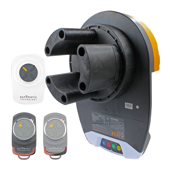
3. Set Up Requirements Fig 3.1 3.1 Kit Contents ITEM DESCRIPTION GDO-12 POWER DRIVE UNIT INTERNAL GEAR ADAPTER (FORKS) HEX SERRATION HEAD SCREW M6 X 20 4 BUTTON TRANSMITTERS 4 BUTTON WALL TRANSMITTER LOCKING BAR COVERS GUIDE PACK VR12 SCREW-EYE PLASTIC WALL PLUG 6.9 X 25 (1”) GDO-12V1 Hiro Installation Instructions... -
Page 7: Pre-Installation Requirements
4. Pre-Installation Requirements IMPORTANT SAFETY INSTRUCTIONS FOR INSTALLATION Warning: Incorrect installation can lead to severe injury. Follow ALL installation instructions. NOTE: Planetary chain equipment must be removed from the door prior to installation of GDO-12V1 HiRo™. 4.1 Door Operation The door must be in good operating condition. The maximum effort to move the door up or down, from stationary, should not exceed 200 Newtons (20 kg force) at the bottom rail. -
Page 8: Opener Safety & Security
5. Opener Safety & Security 5.1 The Door CAN NOT be used by the opener when: MANUAL RELEASE a. There is a locking device installed. b. There is a power failure. 5.2 The Door CAN be used when: WARNING! When operating the manual a. -
Page 9: Door Preparation
6.1 Door Preparation 6.1.1 Preparation a. Check the door’s operation: The door must travel smoothly and be easy to operate by hand. ii. Adjust any tight or twisted guides. iii. Clean the guides if there is any oil or wax present using a suitable white spirit. The only lubricant suitable for use on door guides is silicon spray. -
Page 10: Propping The Door
6.2 Propping the Door 6.2.1 Door prop preparation a. At the end opposite to where the opener will be fitted, check that the door axle is tightened to the bracket securely. (Fig. 6.2) b. Open the door completely and tie safety ropes around the door roll approximately 300 mm from each end. -
Page 11: Setting Limits
6.4 Setting Limits Fig 6.4 6.4.1 Setting Travel Limits HELPFUL TIP: Alternatively set travel limits using transmitter, allowing a. Move the door to the half way position. free movement around the garage to b. Engage the opener by pulling down on the manual release better assess the desired limit positions. -
Page 12: Safety Obstruction Force Test
6.5 Safety Obstruction Force Test WARNING! Take care when testing or adjusting the WARNING! If the door fails these tests, put Safety Obstruction Force. Excessive force may cause the opener into manual mode, only operate SERIOUS PERSONAL INJURY and/or PROPERTY the door by hand and call for service. -
Page 13: Coding Transmitter
6.6 Coding Transmitter 6.6.1 Transmitter Button to Operate Door The GDO-12 HiRo can store up to sixty four (64) transmitters in its memory. a. Press the MODE button to highlight the CODE LED. b. Press OPEN or CLOSE buton until BLUE CLOSE, RED STOP/ SET and GREEN OPEN LEDs are on. -
Page 14: Operation Instructions
7. Operation Instructions IMPORTANT SAFETY INSTRUCTIONS WARNING! TO REDUCE THE RISK OF SEVERE INJURY OR DEATH: (1) READ AND FOLLOW ALL INSTALLATION INSTRUCTIONS. (2) NEVER LET CHILDREN OPERATE OR PLAY WITH DOOR CONTROLS. KEEP THE REMOTE CONTROL AWAY FROM CHILDREN. (3) ALWAYS KEEP THE MOVING DOOR IN SIGHT AND AWAY FROM PEOPLE AND OBJECTS UNTIL IT IS COMPLETELY CLOSED. -
Page 15: How To Use Your Opener
When batteries reach the end of their usual life in accordance with Australian Battery Recycling Initiative please follow the next simple steps for protecting the environment. Refer to the Automatic Technology website for information on where to recycle batteries in Australia. -
Page 16: User Operating Controls
7.2 User Operating Controls Button Function 1. BLUE DOWN ARROW Close Button 2. RED STOP/SET Stop / Set Button 3. GREEN UP ARROW Open Button 4. MODE Mode Selection Button 7.3 Door Status Indicators Door Status Indicators OPEN LED (green) CLOSE LED (blue) STOP (red) Open... -
Page 17: Maintenance
8. Maintenance 8.1 Door Maintenance WARNING! Failure to maintain your garage A poorly maintained door could cause fatal / serious injuries or door may void the warranty on your garage damage to property. door opener. • Frequently examine the door, particularly the cables, springs and mountings for signs of wear, damage or imbalance. -
Page 18: Troubleshooting Guide
9. Troubleshooting Guide Symptom Possible cause Remedy The opener does not work Garage door in poor condition e.g. Check the door’s operation - see monthly from the transmitter springs may be broken maintenance (Section 8) The opener does not have power Plug a device of similar voltage (e.g. -
Page 19: Appendix
10. Appendix A - Adjustment Mode Parameters Adjustment Mode Adjustments can be made to functions such as Light times, Auto Close functions etc. The below table shows the parameters that can be altered. a. Press and release the MODE button until the Spanner LED (Adjustment Mode) is highlighted. b. -
Page 20: C - Led Status
Appendix C - LED Status Operation indicators The below table displays the status of the opener when LEDs are activated. LED Indicators Status CODE LED Flickers with transmitter activity or indicating transmitter may not be coded to the opener. LIMIT LED Indicates the opener is in Limit Set Mode SPANNER LED Indicates the opener is in Adjustment Mode... -
Page 21: D - Setting Limits Via Transmitter
Appendix D - Setting Limits via Transmitter The GDO-12 HiRo™ has the ability to set travel limits using a transmitter, allowing free movement around the garage to better Button 1 Button 2 assess the desired limit positions. In order to use a transmitter, (Inch Open) (Set) it must first have at least one of its buttons coded to the door... -
Page 22: E - Additional Transmitter Functions
Appendix E - Additional Transmitter Functions E.1 Transmitter Button to the Courtesy Light The transmitter can be programmed to operate the courtesy light on Operate Light the opener independently of the door moving. Door a. Press the MODE button to highlight the CODE LED if not already highlighted. -
Page 23: Warranty And Exclusion Of Liability
REGISTER ONLINE TODAY! Register your Product to take advantage of convenient service and support at www.ata-aust.com.au/register This Warranty is given by Automatic Technology (Australia) Pty Ltd (ABN 11 007 125 368) (ATA), 6-8 Fiveways Boulevard, Keysborough 3173, 1300 769 850, sales@ata-aust.com.au. - Page 24 © September 2018 Automatic Technology (Australia) Pty Ltd. All rights reserved. No part Automatic Technololgy (Australia) Pty Ltd of this document may be reproduced without ABN 11 007 125 368 prior permission. In an ongoing commitment 6-8 Fiveways Boulevard to product quality we reserve the right to Keysborough, Victoria, 3173, Australia change specification without notice.
Need help?
Do you have a question about the Hiro GDO-12V1 and is the answer not in the manual?
Questions and answers