Table of Contents
Advertisement
Quick Links
Download this manual
See also:
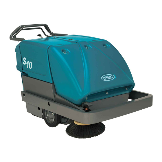
Operator's Manual
Advertisement
Table of Contents

Related Manuals for Tennant S10


Summary of Contents for Tennant S10
- Page 1 Sweeper Service Information Manual 331585 Rev. 00 (6-2007) *331585* www.tennantco.com...
- Page 2 2. (B) Identify the machine serial number from the data plate. Refer to the TENNANT Parts Manual. NOTE: Only use TENNANT Company supplied or equivalent parts. Parts and supplies may be ordered online, by phone, by fax or by mail.
-
Page 3: Table Of Contents
........S10 331585 (6- -07) - Page 4 ........S10 331585 (6- -07)
-
Page 5: Safety Precautions
- - Make Sure All Safety Devices Are In Place And Operate Properly. This machine is designed solely for sweeping dirt and dust in an indoor environment. Tennant does not 3. When Using Machine: recommend using this machine in any other - - Go Slow On Grades And Slippery environment. - Page 6 FOR SAFETY LABEL - - LOCATED LOCATED NEAR CHARGER. ON THE CONTROL PANEL. BACK STRAIN LABEL - - LOCATED ON THE TOP OF THE HOPPER. BATTERY CHARGING LABEL - - LOCATED ON THE LEFT SIDE PANEL. S10 331585 (6- -07)
-
Page 7: General Machine Information
* Call Technical Services if Diagnostic Time Exceeds One Hour With Unknown Cause or Course of Action NOTE: Troubleshooting charts may be shown with optional equipment. The optional equipment may not be specified in these charts. Some machines may not be equipped with all components shown. S10 331585 (6- -07) -
Page 8: General Machine Dimensions/Capacities
Belt Type Phase Charger: Auto / Selectable AC Voltage Input 50/60 100--240 Type kW (hp) Electric Motor Propelling 0.75 (1) Type Quantity Volts Ah Rating Weight Batteries 155 @ 20 hr rate 38 kg (83 lb) S10 331585 (6- -07) -
Page 9: Tires
250 mm x 51 mm (10 in x 2 in) Rear (1) Solid 130 mm x 38 mm (5 in x 1.5 in) MACHINE DIMENSIONS 1570 mm (62 in) 990 mm-- 1120 mm (39 in-- 44 in) 920 mm (36.25 in) 03131 S10 331585 (6- -07) - Page 10 General Machine Information S10 SERVICE INFORMATION S10 331585 (6- -07)
-
Page 11: Maintenance & Repair
* Call Technical Services if Diagnostic Time Exceeds One Hour With Unknown Cause or Course of Action NOTE: Troubleshooting charts may be shown with optional equipment. The optional equipment may not be specified in these charts. Some machines may not be equipped with all components shown. S10 331585 (6- -07) -
Page 12: Maintenance Chart
Check for damage, wear, debris Hopper Check seals for damage and wear 25 Hours Battery cells Check electrolyte level Main brush Check floor pattern (after initial 25 hours only) Drive chains Check and adjust tension (after initial 25 hours only) S10 331585 (6- -07) - Page 13 Check lubricant level LUBRICANT/FLUID DW -- Distilled water SPL -- Special lubricant, Lubriplate EMB grease, TENNANT Part No. 01433--1 SO -- Spray lubricant GL -- SAE 90 Weight gear lubricant NOTE: More frequent intervals may be required in extremely dusty conditions.
-
Page 14: Lubrication
REAR CASTER Lubricate the rear caster after every 50 hours of DIFFERENTIAL operation. Lubricate the differential (B) every 100 hours of operation. The differential grease fitting is located on the drive shaft inside the drive sheave. S10 331585 (6- -07) -
Page 15: Side Brush Gear Box
6 mm (0.25 in) of the top. 03144 SELF ADJUSTING SHEAVE Lubricate the sheave shaft after every 100 hours of operation. Avoid getting oil on the belt or sheave belt surfaces. 03141 S10 331585 (6- -07) -
Page 16: Batteries
Objects made of metal can potentially short circuit the batteries. Keep all metallic objects off the batteries. 04380 Replace any worn or damaged wires. Replace any defective batteries. To dispose of batteries, contact a battery dealer or your Tennant Service representative. S10 331585 (6- -07) -
Page 17: Charging Batteries
Keep battery compartment open MAINTENANCE). when charging. 3. Remove the battery compartment covers for FOR SAFETY: When servicing batteries, wear ventilation when charging. protective gloves and eye protection when handling batteries and battery cables. Avoid contact with battery acid. S10 331585 (6- -07) - Page 18 Output current exceeds a limit. Disconnect charger cord, wait 30 seconds, times repeatedly then plug back in. If fault continues replace charger or contact TENNANT Service. 100% LED blinks Abnormal cycle. Safety timer exceeded Battery maintenance required or replace while the 50% and the 18 hour charging time.
-
Page 19: Electric Motors
03151 A. Motor B. Clutch Plate C. Clutch Plate Bolt D. Bolt Slot E. Forward Belt Idler Sheave F. Reverse Propelling Belt G. Forward Propelling Belt H. Reverse Belt Idler Sheave I. Belt Guide S10 331585 (6- -07) - Page 20 11. Check steering effort. After repairing or replacing drive system parts, effort may increase due to poor alignment. To correct, do the following: A. Loosen the bearing flanges as well as the split coupling bolts. B. Snug one split coupling bolt. S10 331585 (6- -07)
-
Page 21: Replace Propelling Belts
(not shown). 10. Adjust the belt as described in CHECK AND ADJUST PROPELLING BELT TENSION. 11. Replace the right side cover and bumper, and the access cover. 12. Replace the debris hopper. 13. Lower the filter cover. S10 331585 (6- -07) -
Page 22: Replace Side Brush Belt
3. Place the side brush arm in the raised position. 10. Replace the debris hopper. 4. Remove the four speed reducer mounting bolts and the speed reducer from the side brush arm. S10 331585 (6- -07) -
Page 23: Main Brush Belts
8. Run the machine to ensure the belt (B) rests in Position the side brush belt (C) over the motor the sheave properly. sheave (B) and under the belt guide (D). 9. Replace the right side bumper and cover, and access cover. S10 331585 (6- -07) -
Page 24: Vacuum Fan Belt
4. Position the new belt on the motor sheave and the vacuum fan sheave. 5. Adjust belt tension as described in CHECK AND ADJUST VACUUM FAN BELT TENSION. 6. Replace the rear panel. 06320 A. Vacuum Fan B. Adjustment Slot C. Stud Nut S10 331585 (6- -07) -
Page 25: Wheel Drive Chains
Make sure the chain touches the floor at chains with a penetrating--type spray lubricant after all times. every 100 hours of operation. The wheel drive chains should have 15 mm (0.5 in) slack measured midway between the sprockets. 03139 S10 331585 (6- -07) -
Page 26: Brushes
NOTE: Do not force the main brush onto the drive 5. Place the main brush lift handle in the (Main hub. When the main brush slots and drive hub keys Brush Up) position. are properly aligned, the main brush will easily engage the drive hub. S10 331585 (6- -07) -
Page 27: Side Brush
2. Secure the side brush (A) with the mounting hardware (B). 3. Check the side brush adjustment as described in ADJUSTING THE SIDE BRUSH. If any adjustments are made, recheck the main brush pattern before operating the machine. S10 331585 (6- -07) -
Page 28: Installing The Side Brush
5. Secure the side brush to the drive shaft with the mounting hardware. NOTE: It may be necessary to readjust the side brush drive belt tension after adjusting the side brush height. 03159 A. Hopper B. Hanger Bracket Bolts S10 331585 (6- -07) -
Page 29: Adjusting Dust Filter To Hopper Sealing
-- it should be able to the machine. Always wear eye protection when go down and return to its original position. using compressed air. FOR SAFETY: When servicing machine, wear eye and ear protection when using pressurized air or water. S10 331585 (6- -07) -
Page 30: Removing The Dust Filter
2. Position the filter hold-down plate on the filter. 3. Secure the front filter cover on the filter frame with the six front filter cover screws. 03157 S10 331585 (6- -07) -
Page 31: Hopper Top Seal
Inspect the seals for damage and wear daily. The main brush skirts should clear the floor by 2 mm (0.06 in). Inspect the skirts for damage and wear and proper floor clearance daily. 02347 S10 331585 (6- -07) -
Page 32: Propel Handle Assembly
7. Reattach the ball joint to the propel handle assembly. 8. Start and test the machine. Squeeze both propel handles to ensure the machine moves in both directions. 9. Reinstall the rear cover and battery compartment covers. S10 331585 (6- -07) -
Page 33: Transporting The Machine
4. Park the machine in a cool, dry area. 03136 4. Secure the rear of the machine by wrapping straps around the stationary handle and fastening them to the truck or trailer. S10 331585 (6- -07) - Page 34 Maintenance & Repair S10 SERVICE INFORMATION S10 331585 (6- -07)
-
Page 35: Electrical Troubleshooting Information
* Call Technical Services if Diagnostic Time Exceeds One Hour With Unknown Cause or Course of Action NOTE: Troubleshooting charts may be shown with optional equipment. The optional equipment may not be specified in these charts. Some machines may not be equipped with all components shown. S10 331585 (6- -07) -
Page 36: Electrical Symbols & Abbreviations
BATTERY NON- -ACTIVE INFORMATION & COLOR POSITIVE NEGATIVE WIRE Abbreviations Amps Alternating Current Battery Discharge Indicator Circuit Breaker Fuse Relay Coil Motor N.C. Normally Closed N.O. Normally Open S or SW Switch Timer Volts, Direct Current S10 331585 (6- -07) -
Page 37: Electrical Schematic
S10 SERVICE INFORMATION Electrical Troubleshooting Electrical Schematic 1040284 - - ALL S10 331585 (6- -07) -
Page 38: Wire Harness Drawing
Electrical Troubleshooting S10 SERVICE INFORMATION Wire Harness Drawing 354572 Ref. Serial Number Description Qty. (000000-- Harness, Main, 24vdc [S10] S10 331585 (6- -07) -
Page 39: Key Off Power Distribution
9/WHT HOUR METER 6/BLU 4/YEL 1/RED 25 AMP ONBOARD CHARGER B- - CHARGER WIRING CHARGER WIRING AC CORD Wiring Color Codes Hour Meter is ON whenever Key Switch is turned ON (unless charger is plugged in). S10 331585 (6- -07) -
Page 40: Key Off Power Distribution (Charging)
9/WHT HOUR METER 6/BLU 4/YEL 1/RED 25 AMP ONBOARD CHARGER B- - CHARGER WIRING CHARGER WIRING AC CORD Wiring Color Codes Hour Meter is ON whenever Key Switch is turned ON (unless charger is plugged in). S10 331585 (6- -07) -
Page 41: Key On Power Distribution
If battery voltage drops below 20.76 VDC (1.73 Wiring Color Codes Volts per cell), the Battery Discharge Indicator will open pins 3 & 4, shutting the machine OFF. Hour Meter is ON whenever Key Switch is turned ON (unless charger is plugged in). S10 331585 (6- -07) -
Page 42: Filter Shaker Circuit
Opening the Key Switch signals the Shaker Timer (TMR1) to begin a 20 second cycle to close the contacts between pins 1 & 2 of the Shaker Timer (TMR1). The Shaker Switch (SW2) must be closed to allow Shaker Motor (MG1) to operate. S10 331585 (6- -07) -
Page 43: Filter Shaker System On
Opening the Key Switch signals the Shaker Timer (TMR1) to begin a 20 second cycle to close the contacts between pins 1 & 2 of the Shaker Timer (TMR1). The Shaker Switch (SW2) must be closed to allow Shaker Motor (MG1) to operate. S10 331585 (6- -07) - Page 45 We Need Your Help... As part of Tennant’s Zero Defects Program, we want to know about errors you have found or suggestions you may have regarding our machine manuals. If you find an error or have a suggestion, please complete this postage-paid form and mail it to us.
- Page 47 We Need Your Help... As part of Tennant’s Zero Defects Program, we want to know about errors you have found or suggestions you may have regarding our machine manuals. If you find an error or have a suggestion, please complete this postage-paid form and mail it to us.
Need help?
Do you have a question about the S10 and is the answer not in the manual?
Questions and answers