
Related Manuals for Leviton Z-MAX Series


Summary of Contents for Leviton Z-MAX Series
- Page 1 User Guide Z-MAX EMOTE ELAY ANELS IGHTING ONTROL ELAY ANELS ...another Z-MAX product by Leviton Manufacturing...
-
Page 3: Table Of Contents
Table of Contents, Table of Contents Overview Introduction ................1 Installation Overview ..............1 Inspection ................. 2 Physical Description ..............2 Control Overview ............... 3 Conduit Entry Locations ............. 4 Line & Load Circuit Wiring ............4 Turn On ..................4 Warnings ................... - Page 4 Table of Contents, Line and Load Circuit Wiring ............. 30 Testing the Circuits.............. 30 Installing Relay Cards ............30 Wiring the relays ..............31 Control Electronics Power Wiring ..........38 Circuit Schedule ..............41 Master/Remote Network Interconnection RJ-45 Pinout ............... 46 Termination ................
- Page 5 Table of Contents, Configuration of Remote Relay Cabinets without Dipswitches or via USB ................... 78 Configuration of Master Control Panel ........79 Enable Master/Slave Communication ........79 Enabling Master/Slave Communication ......... 80 Setting the Total number of Remote Relays ......80 Communication Verification ............
- Page 6 Table of Contents, Page vi...
-
Page 7: Introduction
Overview, Introduction Overview Introduction The Z-MAX Remote Relay Panels, also referred to as Z-MAX Slave Relay Cabinets, are designed for remote installation and mounting where relay switching from 4 to 48 load circuits is desired, but control intelligence, programming, and interface to other systems is required at a central location. -
Page 8: Inspection
Inspection Carefully unpack the relay cabinet, and inspect to make sure there is no hidden shipping damage. Report any damage to the freight carrier who delivered the system. Claims for damages are filed with the freight carrier. In case of damaged components, your relay cabinet may be serviced in the field with factory replacement parts. -
Page 9: Control Overview
Control Overview The Leviton Z-MAX remote relay cabinets use an intelligent central control card (Digital Main Control Module) and a dedicated system of networking wiring, allowing for control of the... -
Page 10: Conduit Entry Locations
Conduit Entry Locations The cabinets have been designed with specific locations supporting conduit entry for line and low voltage circuits. There are specific areas of the cabinet which are restricted from some or all types of conduit access. Reference the Physical Installation section of this manual for specific details. -
Page 11: Warnings
Overview, Turn On Warnings • To be installed and/or used in accordance with appropriate electrical codes and regulations. • To be installed by a qualified Electrician. • DO NOT CONNECT line voltage wires to low voltage terminals. • Mount in a location where audible noise is acceptable. •... -
Page 12: Installation
Installation Installation Checklist Install the cabinets by following these simple steps: Unpack the system Step 1: Report any damage to the freight carrier Step 2: If appropriate, remove any covers and/or doors Step 3: If appropriate, remove the mounting plate Step 4: assembly and store where damage will not occur to the electronics... - Page 13 Overview, Installation Checklist Make programming adjustments at the master Step 19: control module so that newly installed remote relays usage correctly. Z-MAX Remote Relay Panel User Guide, Revision A 8/2005 PK-93194-10-00-0A Page 7...
- Page 14 Page 8...
-
Page 15: Relay Cabinet Mounting
, Flush Mounting Relay Cabinet Mounting There are several steps required when mounting your relay cabinet: Install the flush mounting kit if appropriate Step 1: Plan your conduit runs & layout Step 2: Plan your physical mounting, the connection Step 3: between the cabinet and the wall Mount the cabinet to the wall Step 4:... -
Page 16: Special Instructions For Flush Mount Kit Installation
Special Instructions for Flush Mount Kit Installation Locate where the cabinet will be hung in the wall. Step 1: Choose a location in a dry area that is convenient to the branch circuit panel Be careful to remove the ground wire from the door. Step 2: It is attached using a spade connector. - Page 17 , Flush Mounting Remove the nut holding the door lock in place Step 10: Remove the lock and its trim ring (Looks like a Step 11: washer) Discard the trim ring and reinstall the lock Step 12: Loosen the screws holding the door hinges to the Step 13: cabinet.
-
Page 18: Selection Of A Mounting Location
Selection of a Mounting Location Choosing a mounting location for your cabinet is critical to the overall success and ease of installation. Each style of cabinet has it’s unique wiring requirements which must be observed. Please review the next few pages, which describe and illustrate these mounting requirements. -
Page 19: Preferred Areas For Conduit Entry
, Preferred areas for conduit entry Cabinet MAX BTU/HR 4 Relay Cabinet 8 Relay Cabinet 24 Relay Cabinet 48 Relay Cabinet 1166 Preferred areas for conduit entry Your relay cabinet has been designed to be easy to install with a variety of installation options to fit many applications. - Page 20 Conduit Entry Low or High Voltage Low Voltage (not both) Wiring/Conduit Wiring/Conduit Entry Area Entry Area 2¼" 1 A 2 A G S L O W B L O W F U S E Connector Grounding Screws (typ) NO CONDUIT ENTRY! High Voltage Wiring Area...
- Page 21 , Preferred areas for conduit entry High Voltage Pass through below control module mounting plate Low Voltage Area Transformer located underneath control module Transformer Connections this area below control module High Voltage Area Grounding Points 24 & 48 Relay Cabinets Conduit Entry (24 relay cabinet shown, 48 similar) Z-MAX Remote Relay Panel User Guide, Revision A 8/2005 PK-93194-10-00-0A...
-
Page 22: Suggested Layouts
Suggested Layouts The "right" layout for your application is a decision only you can make. The layouts depicted in the following illustrations show some simple and effective systems which you’re welcome to use and adapt to your particular installation. Wiring Raceway Wiring Raceway Wiring Raceway Feed and/or... -
Page 23: Physical Mounting Requirements
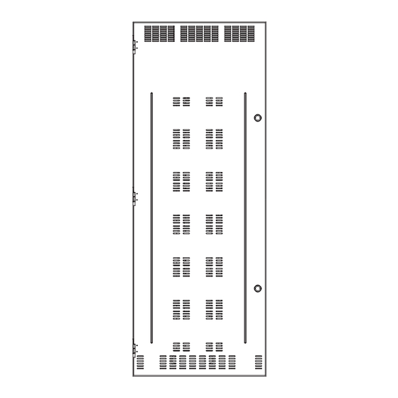
, Physical Mounting Requirements Physical Mounting Requirements Each relay cabinet style has a different set of mounting locations, dimensions, and requirements. Please review the illustrations below which show the details for each cabinet type. 1 0.1 3 4.34 1 0.1 3 FRONT VIEW SIDE VIEW (all dimensions in inches) - Page 24 LINE / LOAD LINE / LOAD CONDUIT ENTRY CONDUIT ENTRY 1" & 1-1/4", 2 1" & 1-1/4", 2 VOLTAGE PLACES PLUS PLACES PLUS CONDUIT 1-1/4" & 1-1/2", 3 1-1/4" & 1-1/2", 3 ENTRY PLACES PLACES 1-1/4" & 1-1/2" 6 PLACES 20 1/4 [514.35] 1 27/32...
- Page 25 , Physical Mounting Requirements LINE / LOAD CONDUIT LINE / LOAD CONDUIT VOLTAGE ENTRY ENTRY CONDUIT 1" & 1-1/4", 2 PLACES 1" & 1-1/4", 2 PLACES ENTRY PLUS PLUS 1-1/4" & 1-1/2" 1-1/4" & 1-1/2", 3 PLACES 1-1/4" & 1-1/2", 3 PLACES 6 PLACES 20 1/4 [514.35]...
-
Page 26: Step-By-Step Mounting
Step 1: Choose a location in a dry area that is convenient to the branch circuit panel. Leviton requires that cabinet mounting hardware Step 2: reach through the drywall to wall studs or other suitable solid backing. However, properly sized struts and suitable hardware can be used. -
Page 27: Master/Slave Network Topology
Master/Slave Network Topology, Master/Slave Network Topology There are some basic rules and requirements of Master/Slave networks which must be observed for your network to function. These rules are as follows: Specification Description Maximum End to End Run Length 1500 feet Maximum number of relays per network (Master + Slave) Maximum number of nodes on the... -
Page 28: Network Topology
Network Topology All Master/Remote panels must be connected in a daisy-chained fashion. For example, please consider the illustrations below: Category 5 or better wiring between cabinets 4 Relay Remote Cabinet 4 Relay Remote Cabinet 4 Relay Remote Cabinet 24 Relay Remote Cabinet 48 Relay Master Cabinet The right way - Daisy-Chain Wiring The wrong way - Star or other scheme... -
Page 29: Network Layout Planning
Master/Slave Network Topology, Network Layout Planning previous section illustrated some technical requirements and physical layout for Master/Slave networks. When planning your network, it’s equally important when considering the numbering of relays. Relays are divided into two types: local and network. The local relays are the relays inside the master cabinet, and the network relays are the remote or slave cabinet relays. - Page 30 cabinet must be configured via USB to start at relay number 73. In summary: • Existing Master Cabinet with (48) relays, relay numbers 1-48 • Existing Remote Cabinet with (24) relays, relay numbers 49-72 • Added Remote Cabinet with (24) relays, relay numbers 49-96, must be reconfigured via USB since out of box the default setup is addressed to relay numbers 49-72 which would have been in conflict with the existing cabinet.
-
Page 31: Relay Numbering Chart
Relay Numbering Chart Leviton recommends that when planning your network, you fill out the chart on the following page, or other similar chart which you prefer to document your system. This completed chart should be stored with your master relay panel complete with the circuit schedules of all of the relay panels. -
Page 32: Relay Numbering Chart
Relay Numbering Chart Panel Starting Ending Panel Name Notes Relay # Relay # Page 26... -
Page 33: Feed And Load Wiring
Feed and Load Wiring, Overview of Power Wiring - Feed\Line Wiring Feed and Load Wiring Overview of Power Wiring - Feed\Line Wiring Wiring is simple. All you need is the following: • Dedicated circuit for control power - Hot, Neutral and Ground •... - Page 34 Inputs Not Common Available & Switch Inputs Connector Relay #1 Relay Relay #2 Input & Outputs Relay #3 (Typical of all relays) Relay #4 Control Power Input Cabinet Connections & Orientation, (4) Relay Panel Page 28...
- Page 35 Feed and Load Wiring, Overview of Power Wiring - Feed\Line Wiring High Voltage Pass through below control module mounting plate Low Voltage Area Transformer located underneath control module Transformer Connections this area below control module High Voltage Area Grounding Points 24 and 48 (not Shown) Cabinet Low Voltage and High Voltage Wire Connections Z-MAX Remote Relay Panel User Guide, Revision A 8/2005...
-
Page 36: Line And Load Circuit Wiring
Line and Load Circuit Wiring Z-MAX relay cabinets have multiple relay circuits of a specific type depending on the cabinet model. For details of the different relay types, please reference the chart on page 32. Testing the Circuits Prior to connecting any circuit to a relay, and after all load and feed connections have been made opposite the relay cabinet, test each circuit by following this procedure: Turn off the breaker feeding the circuit... -
Page 37: Wiring The Relays
Feed and Load Wiring, Line and Load Circuit Wiring Locate the appropriate location for the relay card Step 1: Mounting Screw Location Connector to Relay Bus Board On bottom of Relay Card Align the connector from the relay card with the Step 2: relay bus board and gently push the two together. - Page 38 Relay Type Wire Size Wire Type Torque Z-MAX(Standard, 1-Pole) 20-8 AWG Copper Solid or Stranded 7 in-lbs 2-Pole 20-6 AWG Copper Solid or Stranded 20.5 in-lbs 347V 20-6 AWG Copper Solid or Stranded 20.5 in-lbs Latching 20-8 AWG Copper Solid or Stranded 7 in-lbs Wire Sizes for Relays The diagrams on the following pages show how to wire the relay...
- Page 39 Feed and Load Wiring, Line and Load Circuit Wiring Line (from Distributio Panel) Load Connector Relay #1 (Typical of Relay #2 all relays) Relay #3 Relay #4 Wiring Diagram for 4 Relay Panels, 1-Pole Relay Z-MAX Remote Relay Panel User Guide, Revision A 8/2005 PK-93194-10-00-0A Page 33...
- Page 40 Line (Poles 1 & 2) (from Dist. Panel) Load (Pole 1 & 2) Wiring Typical for all relays WARNING: Miswiring of relays may result in product damage or personal injury. Wiring Diagram for 4 Relay Panel with 2-Pole Relay Card Page 34...
- Page 41 Feed and Load Wiring, Line and Load Circuit Wiring Line (from Dist. Panel) Load Wiring Typical for all relays WARNING: Miswiring of relays may result in product damage or personal injury. Wiring Diagram for 4 Relay Panel 347V Canadian Relay Z-MAX Remote Relay Panel User Guide, Revision A 8/2005 PK-93194-10-00-0A Page 35...
- Page 42 Load Line (From Distribution Panel) Wiring Diagram for Z-MAX (Standard) Relay Card Load - Phase B Line - Phase B (From Distribution Panel) Load - Phase A Line - Phase A (From Distribution Panel) Wiring Diagram for 2-Pole Relay Card Page 36...
- Page 43 Feed and Load Wiring, Line and Load Circuit Wiring Load Line (From Distribution Panel) Wiring Diagram for 347 V Relay Card Z-MAX Remote Relay Panel User Guide, Revision A 8/2005 PK-93194-10-00-0A Page 37...
-
Page 44: Control Electronics Power Wiring
Control Electronics Power Wiring Your relay cabinet requires a specific power circuit for the control electronics. Leviton recommends that this power circuit be dedicated specifically and used only for power to the control electronics. If the control electronics must function during a... - Page 45 Feed and Load Wiring, Control Electronics Power Wiring To connect your relay cabinet’s control electronics to power, please follow the following steps: Connect the relay cabinet to the circuit breaker panel Step 1: using conduit Remove all debris Step 2: Run a dedicated circuit from the circuit panel or Step 3: distribution panel to the relay panel for the control...
- Page 46 Multi-Tap Transformer Cap (wirenut) off unused leads 347V - Orange 277V - Brown Neutral -White 120V - Black Dedicated Circuit 24 & 48 Relay Cabinets Control Electronics Power Wiring Page 40...
-
Page 47: Circuit Schedule
Feed and Load Wiring, Control Electronics Power Wiring Circuit Schedule Relay/Circuit Control Load Circuits Panel Field Luma-Net Analog Relay Load Description Group Breaker Circuit Channel Channel Input Type Watts Z-MAX Remote Relay Panel User Guide, Revision A 8/2005 PK-93194-10-00-0A Page 41... - Page 48 Relay/Circuit Control Load Circuits Panel Field Luma-Net Analog Relay Load Notes/ Group Breaker Circuit Channel Channel Input Type Watts Circuit Description Page 42...
-
Page 49: Master/Remote Network Interconnection
Master/Remote Network Interconnection, Master/Remote Network Interconnection Physically interconnecting your relay panels together on a master/slave network is easy. It requires only the use of category 5 or better network wire, with RJ-45 connectors on each end. Please reference the illustrations below which show the connection locations for the Master/Slave network wiring for each panel type. - Page 50 TB12 ANALOG/SWITCH I/O* JUMPER ON PULLS INPUT HIGH ETHERNET/MODEM SELECTOR S1 THRU S12 JUMPER OFF IS DEFAULT EMERGENCY RELAY Master/ C 2004 LEVITON MFG. CO. EMERGENCY COMMON ALL RIGHTS RESERVED WORLDWIDE HEARTBEAT-C LUMANET EMERGENCY Slave EMERG INPUT - TB21 *...
- Page 51 RELAY 3 CAN2 +24V ETH/MODEM 5V POWER HEARTBEAT-R Switch LEVITON ASSEMBLY Inputs OX-70129-00-00-01 NETWORK +24V OX-70129-00-00-02 BASIC RELAY 4 C 2004 LEVITON MFG. CO. ALL RIGHTS RESREVED WORLDWIDE +24V ETHERNET/MODEM +24V JP41 RELAY 5 RESET +24V ETHERNET MODULE RELAY 6 MODEM...
-
Page 52: Rj-45 Pinout
These two standards are often referenced as TIA- 568A & TIA-568B. Although either is acceptable so long as it is consistent throughout a project, Leviton recommends the use of only the TIA-568B standard. The only difference between the standards is what color wires 79terminate to each of the (8) RJ- 45 pins. -
Page 53: Termination
Read and understand the instruction by the crimpers manufacturer prior to use. Leviton offers a crimper as Leviton part number 47613-EZC. Termination All CAN based networks must be terminated at both ends. The Z- MAX Master/Slave network is no exception. - Page 54 Terminate this cabinet Terminate this cabinet 4 Relay Remote Cabinet 4 Relay Remote Cabinet 4 Relay Remote Cabinet 24 Relay Remote Cabinet 48 Relay Master Cabinet Cabinets requiring termination Page 48...
-
Page 55: How To Terminate Relay Cabinets
TB11 TB12 ANALOG/SWITCH I/O* JUMPER ON PULLS INPUT HIGH ETHERNET/MODEM SELECTOR S1 THRU S12 JUMPER OFF IS DEFAULT EMERGENCY RELAY C 2004 LEVITON MFG. CO. EMERGENCY COMMON ALL RIGHTS RESERVED WORLDWIDE HEARTBEAT-C EMERGENCY LUMANET EMERG INPUT - TB21 * CAN1... - Page 56 Page 50...
-
Page 57: Low Voltage Control Wiring
Low Voltage Control Wiring, Low Voltage Control Wiring The use of low voltage control inputs on Remote Relay panels is only available in software release 1.40 and above for both the master and slave cabinets. If you plan to use this feature, please make sure that all cabinets have been upgraded. -
Page 58: Input Trigger - What Determines An "On
Control Wiring Termination This section gives instructions for terminating all types of low voltage inputs. • Leviton recommends minimum 18AWG stranded wire for all low voltage wiring • Terminate all control wiring directly to the terminal blocks on the printed circuit board. Use a small 1/8-in. flat screwdriver on these terminals •... - Page 59 Low Voltage Control Wiring, and must be above +9vdc. Active Low inputs must connect to the same common at the same potential as the cabinet. To change from an active high input to an active low input, the polarity jumper must change position. There are several illustrations which show the location of these jumpers.
-
Page 60: Low Voltage Input Terminals & Connections
Low Voltage Input Terminals & Connections The next several drawings show the location of inputs in the various cabinet types. Inputs Not Common Active hi/low jumper Available & Switch Inputs Connector Relay #1 Relay Relay #2 Input & Outputs Relay #3 (Typical of all relays) Relay #4... - Page 61 TB11 TB12 ANALOG/SWITCH I/O* JUMPER ON PULLS INPUT HIGH ETHERNET/MODEM SELECTOR S1 THRU S12 JUMPER OFF IS DEFAULT EMERGENCY RELAY C 2004 LEVITON MFG. CO. EMERGENCY COMMON ALL RIGHTS RESERVED WORLDWIDE HEARTBEAT-C EMERGENCY LUMANET EMERG INPUT - TB21 * CAN1...
- Page 62 Page 56...
-
Page 63: Connecting Low Voltage Switches
Connecting Low Voltage Switches, Connecting Low Voltage Switches Z-MAX relay panels support a variety of low voltage switch types such as: • Momentary - provides momentary contacts, triggering alternating on/off actions • Maintained - triggers On action when connection is made, Off action when removed •... -
Page 64: Connecting Low Voltage Switch
Please remember to verify the function of each pin as labeled on the product with the device being wired to ensure that it is wired correctly. Regardless of the pinout of your particular product, the common designations for terminals are as follows: Pin Label Function +24V... - Page 65 Connecting Low Voltage Switches, Insert the wires from the device into the connector Step 2: on the relay cabinet in the appropriate location Tighten the terminal screw, and repeat for all wires Step 3: from the device Plug the terminal block back into the cabinet with the Step 4: screws facing towards you and the wires exiting towards the side or top of the cabinet.
- Page 66 Page 60...
-
Page 67: Occupancy Sensors
Occupancy Sensors, Occupancy Sensor Wiring Occupancy Sensors One of the control input types which your relay cabinet can accept is Occupancy Sensors. When using an occupancy sensor, the cabinet is expecting a DC voltage, between +9V & +24V to trigger an occupied state, or a floating input to indicate an unoccupied state. - Page 68 Twist strands of each lead tightly (making sure that Step 2: there are no stray strands) and push firmly into appropriate plug connector location. Tighten the screws on the plug connector making Step 3: sure that no bare conductor is showing. Plug the connector back onto the control module.
-
Page 69: Photocells
Photocells, Photocell Wiring Photocells The relay cabinet is capable of supporting the following types of photocells: • Switched Photocell (On/Off, trigger point set at photocell) • 0-10V Photocell The configuration and behavior of your photocell is set via software and discussed elsewhere. This seciton only covers installation. - Page 70 Note: If your switching photo- AC Power cell requires +24VDC power, this power can be sourced from Switch Leg PhotoCell the cabinet just like a 0-10VDC photocell. The switch legs should still be between COM & Switch Leg IN terminals Note: Switch Legs must be completly isolated from Photocell AC power and...
-
Page 71: Wiring With An External Power Supply
Wiring with an External Power Supply When needed, an external class 2 power supply can be used to supply power to Low Voltage devices connected to the low voltage inputs. When this is required, wire the system by following the diagram below. Optional LED Device Control Signal... - Page 72 Page 66...
-
Page 73: Power Considerations For Control Systems
This chapter contains information which applies to many Leviton products and is not necessarily limited to the product which is primarily included in this manual. There may be information in this chapter which is not relevant to your particular installation. -
Page 74: Power Requirements & Maximum Run Length
Power Control Device (PCD) - refers to a device which controls • power. Examples of Devices in the Leviton product line which control power are dimming racks, relay panels, A-2000, i-series e, Z-MAX, etc. Generally PCD’s also supply a certain amount of... - Page 75 , Power Considerations for Control Systems One Unit Load = 25mA = .025A Control Station A Unit Load Control Station B Unit Load Same formula < Power Supply's for any other attached Available Unit Load control Station Quantity of Station A's attached Quantity of Station B's attached Load Rating Verification Formula Power Control Devices - Available Supply Current...
- Page 76 Power Control Maxim Supply Power Control Maxim Supply Device (PCD) (VDC) Device (PCD) um # (VDC) # of of Unit Unit Loads Loads NPC – DHV NPC – DLR 12-24 Power Supply Maximum Unit Loads The sum of all devices connected to all power output terminals can not exceed the Maximum number of Unit Loads available in the PCD or supply.
- Page 77 , Power Considerations for Control Systems Z-MAX Remote Relay Panel User Guide, Revision A 8/2005 PK-93194-10-00-0A Page 71...
- Page 78 Control Devices Unit Load Unit Load Station Type Unit Load Unit Load @12VDC @24VDC @ 12VDC @ 24VDC D4200 LCD Z-MAX Digital Switch, 1 Button D4200 Entry (Button), Z-MAX Digital Switch, 2 Buttons D4200 Room Combine Z-AX Digital Switch, 3 Station Buttons D4200 Remote I/R...
-
Page 79: Power Wire - Run Length
, Power Considerations for Control Systems Control Devices Unit Load Unit Load Station Type Unit Load Unit Load @12VDC @24VDC @ 12VDC @ 24VDC Ultrasonic 2-Way Occ. 8 Button Low Voltage Sensor Switch Multi-tech 2-Way Occ, 10 Button Low Sensor Voltage Switch Photocell, odc0p-00w Photocell, pcatr-000... - Page 80 14 AWG (Feet) 12 AWG (Feet) 10 AWG (Feet) 10 Unit Loads 1905 3000 4800 20 Unit Loads 1500 2400 30 Unit Loads 1000 1600 40 Unit Loads 1200 50 Unit Loads 60 Unit Loads 70 Unit Loads 80 Unit Loads 90 Unit Loads 100 Unit Loads 110 Unit Loads...
-
Page 81: Configuration
, Remote/Slave Cabinet Configuration Configuration All of the functional configuration of your relay cabinet is performed at the master control module. However, prior to the master control module being able to address the remote relay cabinets, there are two primary configuration steps which must occur: •Set the Starting Relay Number •Set the starting relay &... -
Page 82: Comments & Examples On Relay Numbering
Comments & Examples on Relay Numbering Please find a discussion with examples of relay numbering found on page 23. This information may be helpful when configuring your relay panels. Configuration of Remote Relay Cabinets with Dipswitches Locate the 8 position dipswitch and set the "MRN" code which corresponds to the starting relay number. -
Page 83: Table Of Mrn Codes & Starting Relay Number
, Remote/Slave Cabinet Configuration Table of MRN Codes & Starting Relay Number MRN Code Start Relay Number Z-MAX Remote Relay Panel User Guide, Revision A 8/2005 PK-93194-10-00-0A Page 77... -
Page 84: Configuration Of Remote Relay Cabinets Without Dipswitches Or Via Usb
To Set the MRN Code: Choose the MRN code that corresponds to your Step 1: starting relay code as shown in the Table of MRN Codes & Starting Relay Number on page 77. Enter the MRN code into the dipswitch by adding the Step 2: value of each lever in the "On"... -
Page 85: Configuration Of Master Control Panel
, Configuration of Master Control Panel cabinet, please reference the instructions contained at our website, www.leviton.com and in your master control panel user guide. Additionally, for this purpose, your PC requires additional software and drivers which must be downloaded from our website. -
Page 86: Enabling Master/Slave Communication
Enabling Master/Slave Communication Press the MENU button to enter the menu structure Step 1: Use the arrow keys and the SELECT/SAVE key to Step 2: navigate to Configuration, System Setup, then Global Defaults Using the arrow keys, find the menu below: Step 3: G L O B A L D E F A U L T S... - Page 87 , Configuration of Master Control Panel Using the arrow keys, find the menu below: Step 3: G L O B A L D E F A U L T S R E M O T R E L A Y S O F F Press SELECT/SAVE until the OFF is blinking, then Step 4:...
-
Page 88: Communication Verification
Using the arrow keys, find the menu below: Step 3: G L O B A L D E F A U L T S R M T D I S C R E T E O F F Press SELECT/SAVE until the OFF is blinking, then Step 4: use the arrow keys or numbers to change it to ON. - Page 89 , Conclusion the inputs act as an extension of the master inputs. To complete the functional programming of your system, please reference your Z-MAX User’s guide which details the remainder of the required programming. Z-MAX Remote Relay Panel User Guide, Revision A 8/2005 PK-93194-10-00-0A Page 83...
- Page 90 Page 84...
-
Page 91: Warranty Information
F.O.B. factory. Leviton is not responsible for removing or replacing equipment on the job site, and will not honor charges for such work. Leviton will not be responsible for any loss of use time or subsequent damages should any of the equipment fail during the warranty period, but agrees only to repair or replace defective equipment returned to its plant in Tualatin, Oregon. - Page 93 Leviton Manufacturing Co., Inc. 59-25 Little Neck Parkway, Little Neck, NY 11362-2591 Telephone: 1-800-323-8920 FAX: 1-800-832-9538 Visit Leviton’s Web site at http://www.leviton.com © 2005 Leviton Manufacturing Co., Inc. All Rights Reserved Specifications and Pricing Subject to Change at any time without notice PK-93194-10-00-0A...
Need help?
Do you have a question about the Z-MAX Series and is the answer not in the manual?
Questions and answers