
Related Manuals for Leviton EZ-MAX PLUS series


Summary of Contents for Leviton EZ-MAX PLUS series
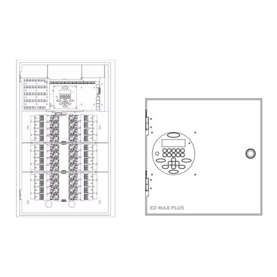
- Page 1 Installation Guide LUS TM EZ-MAX P ELAY ANELS Covering EZ-MAX Plus 8, 16 & 24 Relay Panels Software Revision 1.0 and above.
-
Page 2: Table Of Contents
Table of Contents Read this Before You Begin! Safety Precautions!....................1 Warnings! ......................1 Overview Introduction......................3 Product Specifications and Capabilities ..............4 Installation Overview ..................... 5 Installation Checklist....................6 Relay Cabinet Mounting Selection of a Mounting Location ................7 Suggested Mounting Heights ................ - Page 3 Luma-Net III Wiring Specifications ....................39 Wiring the Phoenix Connector ................40 Emergency Inputs and Outputs ....................45 Terminal Locations ....................46 Appendix A Power-Up and Installation Verification Checklist............ A-1 Appendix B Power Considerations for Control Systems............B-1 Terminology ....................B-1 Power Requirements and Maximum Run Length ..........B-2 Power Wire - Run Length ................
-
Page 4: Read This Before You Begin
Do not use this equipment for other than intended use. All servicing shall be performed by qualified service personnel. SAVE THESE INSTRUCTIONS! Leviton Service and Support: www.leviton.com 1-800-959-6004 Warnings! Conduit Entry Locations: The cabinets have been designed with specific locations supporting conduit entry for line and low voltage circuits. - Page 5 Read this Before You Begin! Warnings! Use this relay cabinet only with minimum 75 C copper wire at 75% ampacity. Disconnect power when servicing the relay cabinet, fixture or when changing lamps. Indoor use only. TO AVOID FIRE, SHOCK OR DEATH: TURN OFF POWER AT MAIN CIRCUIT BREAKER, OR FUSE, AND TEST THAT THE POWER IS OFF BEFORE WIRING, OPENING THE PANEL, OR REPLACING ANY COMPONENT!
-
Page 6: Overview
Overview Introduction Thank you for choosing Leviton’s EZ-MAX Plus line of products for your relay needs. The EZ-MAX Plus product line offers a scalable solution of relay and relay controls that can fit any application with 2 or 3-circuit needs with time clock control. -
Page 7: Product Specifications And Capabilities
Overview Product Specifications and Capabilities Product Specifications and Capabilities The table below gives a general overview of the specifications of all EZ-Max Plus relay products. The table uses the following abbreviations: Y = Yes N = No O = Optional * = A single asterisk in any column indicates that there is support for this feature, however, there are conditions that you should be aware of. -
Page 8: Installation Overview
Inspect your work (REQUIRED FOR ALL CABINETS) (See “Power-Up Step 5: and Installation Verification Checklist” on page 1.). Power-up and test the system. Step 6: Install latest software/firmware from Leviton website, Step 7: www.leviton.com/lms. Perform all necessary configuration. (See the EZ-MAX Plus Step 8:... -
Page 9: Installation Checklist
Overview Installation Checklist Installation Installation Checklist Follow these simple steps to install the cabinet: Unpack the system. Step 1: Report any damage to the freight carrier. Step 2: If appropriate, remove any covers and/or doors. Step 3: If appropriate, remove the mounting plate assembly and store where Step 4: damage will not occur to the electronics. -
Page 10: Relay Cabinet Mounting
Relay Cabinet Mounting There are several steps required when mounting your relay cabinet: Install the flush mounting kit if appropriate. Step 1: Plan your conduit runs and electrical room layout. Step 2: Determine the appropriate methods for mounting your cabinet to the Step 3: wall. -
Page 11: Preferred Areas For Conduit Entry
Relay Cabinet Mounting Preferred Areas for Conduit Entry Preferred Areas for Conduit Entry Your relay cabinet has been designed for easy installation, with a variety of installation options. Please pay close attention to the “allowed” and disallowed” areas for conduit entry. -
Page 12: Sample Electrical Room Layouts
Sample Electrical Room Layouts The "right" layout for your application is a decision only you can make. The layouts depicted in the following illustrations show some simple and effective systems which you’re welcome to use and adapt to your particular installation. Wiring Raceway Feed and/or Feed and/or... -
Page 13: Mounting Provisions And Dimensions
Relay Cabinet Mounting Mounting Provisions and Dimensions Mounting Provisions and Dimensions TOP VIEW LOW VOLTAGE LINE / LOAD CONDUIT ENTRY CONDUIT ENTRY 1" & 1-1/4" [330.2] SIDE VIEW with door SIDE VIEW [19.05] (4 9/32) 19/32 11 21/32 27/32 [108.65] (9/32) 15.28 [101.6]... - Page 14 LINE / LOAD LINE / LOAD CONDUIT ENTRY CONDUIT ENTRY 1" & 1-1/4", 2 1" & 1-1/4", 2 VOLTAGE PLACES PLUS PLACES PLUS CONDUIT 1-1/4" & 1-1/2", 3 1-1/4" & 1-1/2", 3 ENTRY PLACES PLACES 1-1/4" & 1-1/2" 6 PLACES 20 1/4 [514.35] 1 27/32...
- Page 15 Choose a location to mount the cabinet. Make sure the location in a dry Step 1: area that is convenient to the branch circuit panel. Leviton requires that cabinet mounting hardware reach through the Step 2: drywall to wall studs or other suitable solid backing. However, properly sized struts and suitable hardware can also be used.
- Page 16 Line Voltage...
- Page 17 Page 14...
-
Page 18: Line Voltage And Control Power Termination
Line Voltage and Control Power Termination Overview of Power Wiring - Feed\Line Wiring Wiring is simple. All you need is the following: Dedicated circuit for control power - Hot, Neutral and Ground • Individual load wires leaving relays, output circuits. •... - Page 19 Line Voltage and Control Power Termination Overview of Power Wiring - Feed\Line Wiring Ground Point Transformer High Voltage Control Power Connections Connections This Area Figure 6: EZ-MAX Plus 8 Line Voltage Wiring Areas. Page 16...
-
Page 20: Line And Load Circuit Wiring
Line and Load Circuit Wiring EZ-MAX Plus relay cabinets have multiple relay circuits of a specific type depending on the cabinet model. For details of the different relay types, their capacities, and permitted wire sizes, please see “Wire Sizes and Capacities for Relays” on page 18. Testing the Circuits Verify that all load and feed connections have been made before you attempt to connect any circuit to a relay. -
Page 21: Wiring The Relays
CAUSE DAMAGE TO THE RELAY MODULE, THE RELAY CABINET, AND POSSIBLY OTHER SYSTEMS! When driving secondary contactors, EMF may induce significant noise which may cause some units to reset. Installation of MOV may be required. Please contact Leviton support for additional details. Page 18... -
Page 22: Wiring Diagrams
Wiring Diagrams The diagrams on the following pages show how to wire the relay circuits. Load Line Figure 8: Wiring Diagram for EZ-MAX Plus 30-Amp Relay Card Load Line (From Distribution Panel) Figure 9: Wiring Diagram for EZ-MAX Plus 1 Pole Relay Card (latching relay card similar) Load - Phase B Line - Phase B... - Page 23 Line Voltage and Control Power Termination Line and Load Circuit Wiring Load Line (From Distribution Panel) Figure 11: Wiring Diagram for EZ-Max Plus 347 V Relay Card Load Line Load (From Distribution Panel) Load Figure 12: Wiring of Multiple Relays to Common Branch Circuit Breaker Page 20...
-
Page 24: Control Electronics Power Wiring
Control Electronics Power Wiring Your relay cabinet requires a specific power circuit for the control electronics. Leviton recommends that this power circuit be dedicated specifically and used only for power to the control electronics. If any Emergency Circuits are fed or controlled from this... - Page 25 Line Voltage and Control Power Termination Control Electronics Power Wiring Page 22...
- Page 26 Low Voltage...
- Page 27 Page 24...
-
Page 28: Low Voltage Control Wiring
Remote relay panels only support analog control inputs. Control Overview The Leviton EZ-MAX Plus relay products are simple yet powerful, and can be operated by multiple control sources. Control input to a relay cabinet can be any combination of the following: Low Voltage momentary or maintained through a discrete input. -
Page 29: Input Trigger-What Determines An "On
Control Wiring Termination This section gives instructions for terminating all types of low voltage inputs. Leviton recommends minimum 18AWG stranded wire for all low voltage wiring. • Terminate all control wiring directly to the terminal blocks on the printed circuit •... - Page 30 General Requirements for Connecting any Device to Low Voltage Inputs Connect leads per wiring diagram as illustrated in the figures on the Step 1: following pages. Twist strands of each lead tightly (making sure that there are no stray Step 2: strands) and push firmly into appropriate plug connector location.
- Page 31 Low Voltage Control Wiring Control Overview Page 28...
-
Page 32: Low Voltage Switches
ANALOG/SWITCH INPUT/OUT Figure 15: Low voltage terminal layout, 8/16/24 relay cabinets ANALOG/SWITCH I/O* JUMPE SELECTOR S1 THRU S12 JUMPE EMERGENCY RELAY C 2004 LEVITON MFG. CO. COMMON ALL RIGHTS RESERVED WORLDWIDE EMERGENCY EMERG INPUT - TB21 * SWITCH BOARD (OPTIONAL) -
Page 33: Connecting To A Low Voltage Input
Momentary OFF input only Figure 16: Discrete input terminal labels and their meanings —applies to all Leviton products By default, the “IN” or the “ON” terminal is expecting +V to trigger as would be typical with many styles of low voltage switches. If a connection to common is required, it requires some jumper and software reconfiguration. - Page 34 RELAY 3 +24V ETH/MODEM 5V POWER HEARTBEAT-R Switch LEVITON ASSEMBLY Inputs OX-70129-00-00-01 NETWORK +24V OX-70129-00-00-02 BASIC RELAY 4 C 2004 LEVITON MFG. CO. ALL RIGHTS RESREVED WORLDWIDE +24V ETHERNET/MODEM +24V JP41 RELAY 5 RESET +24V ETHERNET MODULE RELAY 6 MODEM...
- Page 35 Low Voltage Switches Plug the terminal block back into the cabinet with the screws facing Step 4: toward you and the wires exiting toward the side or top of the cabinet. Alternatively, the connector can be inserted with the screws parallel to the circuit board and the wires exiting toward you.
-
Page 36: Occupancy Sensors
Occupancy Sensors One of the control input types that your relay cabinet can accept is Occupancy Sensors. When using an occupancy sensor, the cabinet is expecting a DC voltage between +9V & +24V to trigger an occupied state, or a floating input to indicate an unoccupied state. - Page 37 Occupancy Sensors Occupancy Sensor Wiring Page 34...
-
Page 38: Photocells
Photocells The relay cabinet is capable of supporting the following types of photocells: Switched Photocell (On/Off, trigger point set at photocell). • 0-10V Photocell. • The configuration and behavior of your photocell is set via software (see the EZ-MAX Plus Programmer’s Guide for details). This section only covers installation. Photocell Wiring Connect leads per wiring diagram as illustrated in one of the following Step 1:... - Page 39 Photocells Photocell Wiring Note: If your switching photo- AC Power cell requires +24VDC power, this power can be sourced from Switch Leg PhotoCell the cabinet just like a 0-10VDC photocell. The switch legs should still be between COM & Switch Leg IN terminals Note: Switch Legs must be completly isolated from...
- Page 40 Digital...
- Page 41 Page 38...
-
Page 42: Luma-Net
Luma-Net III Luma-Net is Leviton’s proprietary digital architectural lighting control protocol. Luma-Net can be used for the following items: Optional Communication and control by Dimensions 8000 control stations and • accessories. Optional Communication and control by Dimensions 4200 control stations and •... -
Page 43: Wiring The Phoenix Connector
Luma-Net III Wiring Specifications Wiring the Phoenix Connector Connect leads per the wiring diagram below. Step 1: Twist strands of each lead tightly (making sure that there are no stray Step 2: strands) and push firmly into appropriate plug connector location. Tighten the screws on the plug connector—making sure that no bare Step 3: conductor is showing. - Page 44 JUMPER ON PULLS INPUT HIGH ETHERNET/MODEM DMX 512 SELECTOR S1 THRU S12 JUMPER OFF IS DEFAULT EMERGENCY RELAY LUMA-NET TB13** REM+ C 2004 LEVITON MFG. CO. TB 14** EMERGENCY JP36 VOLTAGE INPUT REM- COMMON ALL RIGHTS RESERVED WORLDWIDE HEARTBEAT-C SELECT...
- Page 45 Luma-Net III Wiring Specifications Page 42...
- Page 46 Emergency...
- Page 47 Page 44...
-
Page 48: Inputs And Outputs
Emergency Inputs and Outputs The control card has both an emergency input and output. The input can be driven by a contact closure such as one from a fire alarm or by a low voltage signal capable of sinking 5 mA (3 - 5 volts is emergency off and 0 - 2 volts is emergency on). Emergency output has a common contact and both NO and NC contacts. -
Page 49: Terminal Locations
JP30 ANALOG/SWITCH I/O* JUMPER ON PULLS INPUT HIGH ETHERNET/MODEM SELECTOR S1 THRU S12 JUMPER OFF IS DEFAULT EMERGENCY RELAY LUMA-NET TB13** REM+ C 2004 LEVITON MFG. CO. EMERGENCY EMERGENCY JP36 VOLTAGE INPUT COMMON REM- ALL RIGHTS RESERVED WORLDWIDE HEARTBEAT-C SELECT... - Page 50 EMERGENCY RELAY (OUTPUT) Cabinet From COMMON contact closure EMERGENCY or other source EMERG INPUT - TB21 * EMERGENCY RELAY (OUTPUT) Cabinet COMMON EMERGENCY INPUT - TB21 * EMERG (Upper left hand corner of control module shown) Figure 23: Wiring Diagram for 16/24 relay cabinets showing (2) interconnected Emergency Cabinets.
- Page 51 Emergency Terminal Locations Page 48...
-
Page 52: Power-Up And Installation Verification Checklist
Appendix A Power-Up and Installation Verification Checklist Prior to the application of power to your relay cabinet, all of the following steps must have been successfully executed. Inspect each relay load wiring for incomplete termination Inspect each relay’s load wiring for terminals not completely tightened With each relay in the “off”... - Page 53 Power-Up and Installation Verification Checklist Page A-2...
-
Page 54: Power Considerations For Control Systems
Power Control Device (PCD): refers to a device that controls power. The • EZ-MAX Plus relay panel is an example of a devices in the Leviton product line that controls power. PCD’s supply a certain amount of power to connected low voltage control devices. -
Page 55: Power Requirements And Maximum Run Length
Power Considerations for Control Systems Power Requirements and Maximum Run Length Each Control Device used in your system has a different load (draw) and each PCD can support a different total load (supply.) There are logical steps for determining the total load of your network and verifying that the supply is sufficient: Determine the maximum available current of your supply, be it a PCD or Step 1:... - Page 56 Control Device Loads Control Devices Unit Load Unit Load Station Type Unit Load Unit Load @12VDC @24VDC @ 12VDC @ 24VDC D4200 LCD EZ-MAX Plus Digital Switch, 1 Button D4200 Entry (Button), EZ-MAX Plus Digital Switch, 2 Buttons D4200 Room Combine Z-AX Digital Switch, 3 Station Buttons...
-
Page 57: Power Wire - Run Length
Power Considerations for Control Systems Power Wire - Run Length The maximum total run length of each segment is a function of the total number of unit loads. A run becomes too long when the voltage drop, due to wire size and run length, increases to a point where the station does not have sufficient voltage to operate. - Page 58 This Warranty is void on any product that has been improperly installed, overloaded, short circuited, abused, or altered in any manner. Neither the seller nor Leviton shall be liable for any injury, loss or damage, direct or consequential arising out of the use of or inability to use the equipment. This Warranty does not cover lamps, ballasts, and other equipment which is supplied or warranted directly to the user by their manufacturer.
- Page 59 Leviton Manufacturing Co., Inc. 59-25 Little Neck Parkway, Little Neck, NY 11362-2591 Telephone: 1-800-323-8920 • FAX: 1-800-832-9538 Visit Leviton’s Web site at http://www.leviton.com © 2005 Leviton Manufacturing Co., Inc. All Rights Reserved Specifications and Pricing Subject to Change at any time without notice...
Need help?
Do you have a question about the EZ-MAX PLUS series and is the answer not in the manual?
Questions and answers