
Related Manuals for Brunson 771


Summary of Contents for Brunson 771
- Page 1 Models 771, 75, & 76-RH Optical Tooling Transits Operation and Field Adjustment Manual Instrument Company...
- Page 2 Helping the World Measure Since 1927 www.brunson.us Kansas City, Missouri 8000 E. 23rd Street Kansas City, MO 64129 Tel: 816.483.3187 Fax: 816.241.1945 Copyright 2009-2011 Brunson Instrument Company...
-
Page 3: Table Of Contents
Installing Lighting Accessories 12 Chapter 3: Measuring Techniques 15 Bucking In 15 Autoreflection 17 Autocollimation 19 Collimation 23 Collineation 26 Thank you for Reticle Projection 27 purchasing Measuring With Micrometers 28 a Brunson Transit. Chapter 4: Field Calibration Checks 35 Remember that our customer support does Plate (“Bull’s Eye”) Vial 37 not stop after shipment of Micrometer Checks 38 a product—we are here to “Double Center” Check 40 help you with any measurement challenges Horizontal Axis Runout 41 that you may have. Vertical Spindle Runout 42 ... -
Page 5: Chapter 1: Introduction
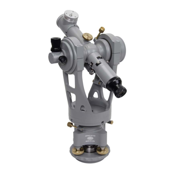
a) They have an extremely straight line of sight. As you focus the telescope from near to far, the line of sight travels in an extremely straight line. That is, picture putting an imaginary, Note: This manual applies to the weightless, taut string down the center of the telescope, following Brunson products: stretching straight out a couple of hundred feet— the string would always be in the center of the crosshairs as 771 and 771‐H Jig Transits you focus from near to far and back again. 75 and 75‐H Optical Transit Squares b) A transit’s three major axes are all mutually orthogonal 76‐RH, 76‐RH190, and 76‐ (all at right angles to each other). There are two rota‐ RH190M Telescopic Transit tional axes on your transit, and one axis which does not Squares rotate (see Figure 1.2). The first rotational axis is the ver‐ tical axis. The spindle and bearings which create the ver‐ At this time, the models 771, 771‐H, tical axis are housed in the transit’s base. The entire up‐ 75, and 75‐H are no longer pro‐ per portion of the transit (standards and telescope) rotate ... - Page 6 Figure 1.1 Orientation to Components 1. Leveling screws (4) 10. Vertical tangent clamp lock 2. “Spider” base 11. Coincidence level 3. Plate vial 12. Cross‐axis telescope lighting adapter 4. Telescope (eyepiece end) 13. Standards 5. Cross‐axis telescope eyepiece 14. Horizontal tangent clamp lock 6. Focus knob 15. Base plate 7. Telescope (objective end) 16. Horizontal tangent adjustment screw 8. 190‐x Optical Micrometer 17. Plate 9. Cross‐axis telescope objective lens 18. Vertical tangent adjustment screw 19. Shifting center Model 771, 75, and 76-RH190 Transits...
- Page 7 doesn’t necessarily mean that the lines would all intersect at the same exact point in space. However, on our transits, these lines do intersect. This is an important characteristic when accuracy is para‐ mount, particularly at shorter distances. Of course, you can’t see this intersection point – it is buried in the middle of the telescope. These are the three distinct characteristics that our telescopes have which allow them to make very precise measurements over rela‐ tively short working distances. However, there is one more very distinctive characteristic which separates Optical Tooling transits from all others – the optical cross‐axis. Our 76‐RH190 has an infin‐ ity‐focused telescope, complete with a second eyepiece and second set of cross wires, housed in the cross axis. This cross‐axis telescope is used in a number of operations to set the main telescope perpen‐ dicular to another telescope or a mirror (which may be mounted on a rotating shaft or other reference plane). So what does a transit do? A transit is a very flexible measuring tool. It can establish vertical or horizontal optical planes which are extremely flat. It can estab‐ lish optical lines which are extremely straight, extending in any di‐ Figure 1.2 rection. Once these planes and lines are estab‐ lished, you can use them as references from which to measure other points of interest. You can determine whether machine components are parallel, flat, level, square, or straight. This means you can evaluate the geometric rela‐ tionships related to the alignment of almost any part, structural component, machine, tool, surface, substrate, wall – or just about any‐ thing else. A very few examples of this would be: Alignment of bearings and bearing journals. ...
-
Page 8: The Three Different Transits
One step “up” is the model 75 or 75‐H (on the left in Figure 1.3). These transits have a cross axis which is hollow and can be seen through. On one side of the cross‐ axis is a clear glass window, and on the other side is a partially re‐ flective mirror. The 75(‐H) does everything that the 771(‐H) can do, but can also be used in con‐ junction with another instrument to produce a very accurate right angle. The most flexible transit (and the only one currently produced) is the model 76‐RH190. The cross‐ axis of this transit contains a tele‐ The 75‐H transit scope that is permanently focused at infinity and is equipped with (above, left) has been dis‐ reticle lighting. A right angle eyepiece is provided as standard equipment on the cross‐axis telescope. The 76‐RH190 may be used continued but many are still in use, and most of to establish straight lines, horizontal or vertical planes, and create the information con‐ accurate right angles with respect to other transits, alignment tele‐ tained in this manual scopes, mirrors, or other physical targets. When the cross wires of still applies. the transit’s cross‐axis telescope are set on those of a reference tele‐ scope or mirror, the main telescope of the transit will sweep a plane at precise right angles to the cross‐axis reference line. Model 771, 75, and 76-RH190 Transits... - Page 9 The “‐H” in the various model numbers refers to a “Hollow” verti‐ cal axis. Transits that have the ‐H designation allow you to look straight down through a hollow vertical spindle and to see targets or collimators which are directly below the base of the instrument. Why do we use four “feet” (leveling screws) instead of three? We are often asked this question, since most theodolites have three leveling screws. The reason is that when adjusting four leveling screws, the instrument height is not affected. When three leveling screws are used, two of them must necessarily form a pivot axis, and the third is used to raise or lower one side to tilt the instrument. It gives the effect shown at left. The red dot indicates the relative instrument height between two positions of the instrument (tilted and not tilted). However, when four leveling screws are used, the instrument position (again, red dot), effec‐ tively, does not change. This gives the effect shown at right. One side goes up by the same amount as the other side goes down, and the instrument pivots at its center, not on one side or the other. This is just another example of the way that we have crafted our instruments to be more accurate at shorter ranges. Over longer distances, minor changes in in‐ strument height are not important. But when measuring very accurately over shorter distances, avoiding changes in instrument height can become crucial. Operation and Adjustment Manual...
- Page 10 Model 771, 75, and 76-RH190 Transits...
-
Page 11: Chapter 2: Getting Started With Your Transit
Chapter 2 ‐ Getting Started with Your Transit In this chapter, we will discuss How to handle your transit Focusing the eyepiece and Removing it from the case telescope Using the shifting center Finding Infinity focus Rough leveling Pointing the telescope Precise leveling Installing lighting accesso‐ The Reticle ries Handle your transit with care Note that these products are precision instruments and should al‐ ways be handled with care. Do not force any of the screws. A firm (but not tight) ten‐ sion gives the best results. Keep your instrument clean and dry. Protect it from the weather if used outdoors. -
Page 12: Removing From The Case
Using the shifting center A special centering mount, different than most of our instrument adapters, may be employed to physically place the horizontal cen‐ ter of the transit in a known location. The shifting center of the transit extends above and below the base plate (visible between the leveling screws and also from below as a 2” diameter ring centered on the bottom of the base plate). This shifting center (radius = 1 ± 0.0001”) fits into special mounts having an accurately bored inner diameter. If the transit is to be located on one of these mounting rings, the leveling screws should be loosened slightly so the base plate can move around in relation to the shifting center. Re‐tighten the leveling screws only after base plate is tightened on the mount. Rough leveling Once mounted on a stand or other stable instrument mount, the fol‐ lowing process will “rough‐level” the transit, meaning that the tran‐ sit will be brought roughly to plumb, and be within range of the precision level vial mounted along the telescope axis. To rough level, loosen any two adjacent leveling screws and turn the four arm ʺspiderʺ base so that two diagonally opposed leveling screws are in line with the principal sighting direction that will be used. Figure 2.2 illustrates this, with the spider base lined up “square” with the telescope and cross axis. Re‐tighten the leveling screws. A circular “bull’s eye” vial rests on the horizontal “plate” above the base but below the telescope axis (Figure 2.3). We call this the “plate vial”. Center this bubble in the following manner: Put a Model 771, 75, and 76-RH190 Transits... -
Page 13: Precise Leveling
Figure 2.2 Figure 2.3 thumb and forefinger on each of two diagonally opposed leveling screws. To move the bubble, turn the leveling screws at the same time, and in opposite directions (thumbs moving together or thumbs moving apart). The bubble will move in the direction of movement of your left thumb. Move the bubble so that it is in the middle of the plate vial, and at least in line with the inscribed circle (it probably won’t be exactly centered). Now move your hands to the other set of leveling screws. Using the same process, move the bubble directly under the inscribed circle in the center of the plate vial. You may have to repeat this entire process a couple of times to get the bubble centered. Keep a light but firm tension on the screws all the time. Never put heavy tension on leveling screws. Now rotate the transit 180° about its vertical spindle. The bubble should stay centered under the inscribed circle. If it doesn’t, the vial is out of adjustment (refer to Chapter 4 of this manual for the calibration procedure to correct this). Precise leveling To precisely level (sometimes called “precision plumb”) the transit using the coincidence vial, rotate the standards of the transit until the telescope is in line with one pair of diagonally opposed leveling screws. Plunge (rotate) the telescope so that the coincidence vial is on top of the telescope, and level the telescope by eye (Figure 2.4). To ... - Page 14 Figure 2.5 screws which are located directly under the telescope. Remove the other half of the error using the vertical tan‐ gent screw. Remember that you can see the bubble by looking into the side of the vial itself rather than into the Note that the transit’s verti‐ turret window—this may help you determine which way cal spindle may be brought the bubble must move. into plumb (exactly vertical) even if the coincidence vial 3. Now rotate the standards 90° so that the telescope is lo‐ itself is not calibrated prop‐ cated directly over the other pair of leveling screws. erly with respect to the tele‐ Bring the bubble to center, using only the two leveling scope barrel. screws under the telescope. 4. From this position, rotate the standards 180°. Again, if the bubble is off center, remove one‐half the error with the vertical tangent screw, and the remaining one‐half error with the two leveling screws which are located un‐ der the telescope. 5. Repeat steps 2‐4, alternating over each pair of leveling screws, until the bubble remains in coincidence in all four “compass point” positions. Model 771, 75, and 76-RH190 Transits...
-
Page 15: The Reticle
The Reticle (crosshairs) The telescope of each Optical Tooling instrument contains a reticle – or crosshair – which defines the center of the line of sight. When you look into a telescope, you see the reticle ʺsuperimposedʺ upon the image of whatever you have the telescope focused on. The reticle is split into four quadrants; two have a Figure 2.6 single ʺwireʺ (filar), the other two have a double ʺwireʺ (bi‐filar). This con‐ The filar/bi‐filar reticle figuration was originally adopted be‐ image as seen when cause the human eye is extremely looking into the tele‐ good at detecting tiny differences in scope. alignment between closely spaced ob‐ jects. Therefore, this pattern makes it much easier to visually align the reti‐ cle with other images (ex., optical tar‐ gets, scales, and reticle images re‐ flected from mirrors). How to properly focus Focusing sounds easy, but it’s surprising how many people don’t understand the effects of something called parallax. Here’s how to properly focus your instrument. First, point the telescope at a sheet ... -
Page 16: Pointing The Telescope
Pointing the telescope Release both the horizontal and vertical tangent clamp locks, and move the instrument by hand. Precise pointing is accomplished by re‐locking both clamps when you get close to the target, and then turning the tangent adjustment screws for precise placement of the reticle. Both tangent adjustment screws are outfitted with wobble pins which allow for smooth translation of the axes. The final set‐ ting should be made by turning the tangent screw in a clockwise, or pushing, direction. This will eliminate any potential subsequent movement due to friction of the spring‐loaded plungers which op‐ pose the tangent adjustment screws. Installing lighting accessories For certain procedures that we will discuss in this manual, (e.g., col‐ limation, autocollimation, and reticle projection) it is necessary to illuminate the reticle of your transit from the inside. A model 76‐x transit has two reticles (one in the main telescope and one in the cross‐axis telescope) which may need to be illuminated, depending upon what you are doing. Illuminating the cross‐axis telescope reticle. Your transit comes equipped with a light source for the cross‐axis telescope (model 76‐ Model 771, 75, and 76-RH190 Transits... - Page 17 x only). This LED light source fits into the receptacle (red arrow in Figure 2.8). The supply transformer works with either 110V or 220V sources. Installation or removal of the light source is simple and quick. Simply install the two‐ way adapter on the cross‐axis lighting receptacle, and push the LED lamp housing in until it clicks into place. The light source has an in‐line switch for easy control of the light. Remember that the focus of the cross‐axis telescope is per‐ manently fixed at infinity. This telescope is meant to be used as a collimator or autocollimator. We will discuss this more, later on in the manual. Illuminating the main telescope reticle. When you wish to Figure 2.8 use the main telescope for collimation, autocollimation, or reticle projection, you must install a model 196‐1 combination eyepiece unit. To do this, remove the short section of the main telescope bar‐ rel located just in front of the eyepiece (See Figure 2.9), and replace it with the 196‐1 eyepiece adapter. Note that the 196‐1 has a knurled lock ring which allows you to tighten the adapter in any given orientation on the telescope barrel. Before installing this eyepiece adapter on the telescope, make sure the knurled lock ring (red arrow in Figure 2.10) is secured against the adapter. It should be “bottomed out” on the threads rather than loose on the threads or near the open end of the adapter. Then thread the adapter into the main telescope barrel as far as you can. Next, back off the adapter to the de‐ sired radial orientation (lamp receiver pointing up or pointing Figure 2.9 down) and lock it in place by turning the knurled lock ring ...
- Page 18 Later in this manual, we will discuss some of the optical tooling techniques which re‐ quire backlighting of the reti‐ cle using one of these adapt‐ ers. Figure 2.10 Model 771, 75, and 76-RH190 Transits...
-
Page 19: Chapter 3: Measuring Techniques
Chapter 3 ‐ Measuring Techniques There are many jobs that you can do with your transit, which may be purchased with a 190‐type micrometer in a standard configura‐ tion. You can evaluate a number of alignment‐related characteris‐ tics of machinery or other structures, such as straightness, plumb, level, flatness, and others. However, to perform certain Optical Tooling procedures, other accessories are required. We will men‐ tion some of these accessories as we discuss the related topics. In this chapter we will discuss the following topics: “Bucking in” Collineation Autoreflection Reticle projection Autocollimation Measuring with micrometers Collimation This discussion is meant to make you aware of some of the Optical Tooling procedures that you can use in alignment and measure‐ ment work. This manual is not a good substitute for our training classes, in which we offer hands‐on training of these and many other Optical Tooling techniques. We’ll explain what these terms mean, and how to accomplish them using your transit. “Bucking in” In many alignment jobs, it is necessary to put the line of sight of your transit directly on a line created by two known reference tar‐... - Page 20 4. Set to far target. Focus the telescope on the far target and set the crosswires directly over that tar‐ get using the horizontal and/or vertical tangent adjustment screws. If the transit is between the targets (as in Figure 3.2), simply assign one of the targets to be the “far target”, and set on it. 5. Set to near target. Without moving the hori‐ zontal tangent screw or turning the standards of the transit, turn the telescope downward and focus on the second target. Note that if the transit is lo‐ cated between the targets (as in Figure 3.2), you will have to turn the telescope “through” the standards to point in the opposite direction. Regardless of whether you are in a situation like Figure 3.1 or Figure 3.2, this second target will invariably be off to one side of the field of view unless you are in‐ credibly lucky. For purposes of illustration, let’s say that the observed lateral distance to the near target is “L” (see Figure 3.1 or 3.2). Now you must move the transit laterally toward the near target using the cross slide—but how much? The amount that you move the transit depends upon the geometry of the setup. The equation to calcu‐ late the proper amount of shift is: Transit Lateral Shift = L x (D2/D1) Figure 3.1 where D1 = Distance between targets Model 771, 75, and 76-RH190 Transits...
-
Page 21: Autoreflection
D2 = Distance from far target to transit L = Observed distance from line of sight to near tar‐ get The amount of movement will depend upon whether the transit is located between the targets or is not located between the targets. Let’s take a look at these two cases. Note that if the transit is NOT located between the tar‐ gets (Figure 3.1), you will shift the transit “past” the image of the near target, because the ratio D2/D1 will always be larger than 1. “L” is the observed dis‐ tance to the near target, and a shift of greater than “L” will appear to move you to the other side of the near target. When you have made the required shift using a cross slide, proceed to step 6. Note: When the transit is in between the targets, and just about equidistant from both, you can sim‐ ply pick one of the targets as the “far” target. Then use the rules as well as the definitions of D1 and D2 to calculate the shift required to buck the transit in Figure 3.2 to both targets. As long as you are consistent with your arbitrary definitions of “near” and “far”, you will be successful. On the other hand, if the transit IS located between the tar‐ gets (Figure 3.2), you will not shift the transit even as far as the near target, because the ratio D2/D1 will always be less than 1. Again, “L” is the observed offset distance from the near target, and a shift of less than “L” will not even move your line of sight as far as the near target. When you have made the required shift, proceed to step 6. 6. Now simply repeat steps 4 and 5 until the transit’s reticle remains centered on each target as the telescope is rotated from one target to the other, and no more adjustment is required. When this is accomplished, the transit is “bucked in” to the line defined by those targets. ... - Page 22 Here are the basic steps for autoreflection: 1. Define the “working” mirror. We’ll assume that you have a mirror situated at the end of a shaft or mounted in a machine tool chuck, or in some other relevant location. 2. Install proper autoreflection target. Mount an autore‐ flection target (example shown in Figure 3.4) on the objec‐ tive end of the telescope. We have two different basic An autoreflection target is types. The type in Figure 3.4 is used for longer distances. mounted on the objective The other type has a smaller target printed on glass, is end of a telescope to help used for closer distances, and often requires internal center a reflected line of lighting of the transit. sight on the telescope it‐ self. Note that if you have 3. Roughly position the transit. Position the instrument lots of experience and a stand in front of the mirror by finding the reflection of convenient setup, using your own eye in the mirror, and then putting the stand’s an autoreflection target is instrument mount on the line between your eye and the not mandatory. Model 771, 75, and 76-RH190 Transits...
-
Page 23: Autocollimation
mirror. Mount the transit to the stand. 4. Point at the mirror. Point and focus the telescope at the A precision lateral slide center of the mirror, then lock the horizontal and vertical allows shifting the instru‐ axes with the tangent lock screws. ment back and forth; a pre‐ cision lift allows moving 5. Set on the “far” target. Focus the telescope to view the the instrument up and autoreflection target (or the end of the telescope itself) in down. the mirror. This is the “far target”. Just as when “bucking in” before, make angular adjustments as needed to align the reticle with the far target. 6. Set on the “near” target. Now focus the telescope to view the mirror itself. This is the “near target”. Make lat‐ eral (shifting) adjustments left and right, or up and down, as needed to align the crosswires generally with the cen‐ ter of the mirror. You can approximate this if the mirror has no target printed on its surface. 7. Alternately repeat steps 6 and 7 until no further adjust‐ ment is needed. Autocollimation Ultimate accuracy in angular control requires the use of autocollima‐ tion. In autoreflection, the reticle of the telescope is aligned with the reflected image of a target which is mounted on the objective end of A reticle image which is re‐ the telescope itself. But in autocollimation, the reticle is aligned flected from a mirror is only ... - Page 24 Above: the reflected reticle is seen off‐center. After the Follow these steps for autocollimation: transit is adjusted, the re‐ flected image is brought 1. Install transit illumination. Install one of our lighting directly into register with accessories into the barrel of your telescope (described in the transit’s actual reticle Chapter 2). Turn on the light source. (below). 2. Autoreflection. Set your transit perpendicular to the mirror using the technique of autoreflection (discussed in the previous section). 3. Focus at infinity. Once you have autoreflected the tran‐ sit, you may be tempted to turn on the transit’s light source and try to focus on the reticle image that is re‐ flected from the mirror. You can try this, but you may have trouble finding the image due to the fact that autoreflection does not always set the transit perpendicu‐ lar to the mirror within the minimal range required for autocollimation. If you can’t find the reflected reticle im‐ age, focus the instrument at infinity using the procedure discussed in Chapter 2. Remember that at infinity, even the tiniest angular difference can make very large shifts in the apparent position of the reflected reticle. This Model 771, 75, and 76-RH190 Transits...
- Page 25 “leverage” is what gives the technique of autocollimation its capability for extreme accuracy, but it’s also what makes the reflected reticle image (at infinity) more diffi‐ cult to find. Once you have focused the telescope at infinity, proceed to the next step. But remember, don’t change the telescope focus when performing the next step. 4. Center transit on “far” target. (Put reflected reti‐ cle image over actual reticle.) See if you can lo‐ Remember that when focused cate the reticle image that is reflected from the at infinity, only the transit’s “working” mirror. Use the horizontal and verti‐ angular controls produce visi‐ cal tangent adjustment screws on the transit to ble results. Lateral shifts us‐ rotate the telescope slightly in the elevation (up ing a cross‐slide or precision and down) or azimuth (left and right) directions. lift will not help you align to Watch for the reflected image. Performing the the reflected reticle when fo‐ autoreflection procedure should have put you cused at infinity. right in the ballpark, but small adjustments may still be needed to find the reflected reticle image. Once you find it, we’ll define it as the far target. Make an‐ gular adjustments as needed to align the reflected reticle image directly over the transit’s internal reticle. 5. Center transit on “near” target. If you had to move sig‐ nificantly to find the reflected reticle image, or if you found only a partial or poor quality reflected image, you probably need to shift the transit laterally up/down or right/left in order to center it more precisely on the work‐ ing mirror. This type of problem often indicates that you are looking at the edge of the mirror rather than a full‐on, ...
- Page 26 2. Make the main telescope square to the vertical spindle. We must bring the main telescope axis “square” to the vertical spin‐ dle (See Figure 3.6). This may be accom‐ plished by precise leveling the transit as discussed in Chapter 2 (“Precise Leveling”). Precise leveling (a.k.a. precision plumbing) actually accomplishes two things at once. First, the transit’s vertical spindle is brought to plumb (i.e., straight up and down; parallel to the gravity vector). Sec‐ ond, the main telescope is brought to hori‐ zontal, which of course makes it square to the vertical spindle (Figure 3.6). This latter part is what we care about—we want the main telescope perpendicular to the vertical spindle. When this is true, the cross scope and the main scope will “follow” each other as the transit is rotated in the azimuth di‐ rection, about its vertical spindle. That is, the line of sight of both the main telescope and the cross‐scope will be in the same Figure 3.7 horizontal plane. Therefore, if you turn the main telescope to look at point “A”, and then turn the transit 90°, the cross‐scope will now point at the same point “A”. Now here’s the important part: this is true whether or not the transit remains precisely plumb. As long as you don’t rotate the main telescope up or down with respect to the standards, Model 771, 75, and 76-RH190 Transits...
-
Page 27: Collimation
both telescopes (main and cross‐axis) will rotate in the same plane, even if the transit is tilted from a vertical ori‐ Even when the transit is entation (Figure 3.7). For example, if you now laid the tilted, it is possible to main‐ entire transit over on its side, the main telescope and tain a 90 ° relationship be‐ cross‐scope would still rotate in the same plane around tween the main telescope’s the central axis of the transit. Once you have precision line of sight and the tran‐ plumbed the transit, proceed to the next step. sit’s vertical spindle (which of course is no longer actu‐ 3. Autocollimate the main telescope. Follow the steps pre‐ ally vertical). viously described to autocollimate the main telescope to the mirror. However, you must observe one important difference when performing that process this time. Dur‐ ing the autocollimation process, do not change the relation‐ ship of the telescope to the vertical spindle. That is, leave the vertical tangent adjustment screw alone—don’t use it to tilt the telescope for proper autocollimation. Instead, if you need to tilt the main telescope, use the leveling screws at the base of the transit and tilt the entire transit instead. Once you have achieved autocollimation in this manner, proceed to the next step. 4. Turn transit to autocollimate the cross scope. It should now be a simple matter to turn the transit 90° in order to view the mirror with the cross scope. Rotate the main telescope’s focus knob all the way in the direction opposite of infinity. This keeps the main telescope’s focusing slide from obstructing the view through the cross‐axis tele‐ scope. Be sure the cross scope illumination is switched “on”. Carefully look into the cross scope eyepiece for the ... - Page 28 This is an extremely accurate way to transfer a reference line estab‐ cused at infinity, pointed lished by a second transit or other instrument. at each other, and whose reticles are brought into Remember that if the lines of sight are parallel, it doesn’t mean that registration are said to be they necessarily travel down the exact same line in space— if they “collimated”. did, they would also be defined as “collinear”. Let’s take a closer look at this. Think about walking down a road on a moonlit night. As you walk, you pass a lighted streetlight on the road. As you pass this streetlight, you cast a shadow. Initially, the shadow is behind you, but as you pass the streetlight, it moves around in front of you. The light rays from the streetlight are not all paral‐ lel—they extend out from the source (the lamp in the streetlight) in all direc‐ tions. As you walk, you “pass through” light rays which are going in different compass directions, and your shadow moves around accordingly (Figure 3.9). Now, after you are further down the road away from the streetlight, you notice that you are casting a shadow by the moonlight, off to your left‐hand side. However, it doesnʹt move around you like the shadow from the streetlight did. The shadow cast by the moonlight always appears to be in the same place with respect to your position, regardless of how far you walk down the road. This is because the moon is so far away, light rays that reach the Earth Model 771, 75, and 76-RH190 Transits...
- Page 29 from the moon are effectively parallel. Additionally, when you look straight at the moon, your line of sight is “collimated” or parallel to the moon‐ beams. You can walk back and forth however far you want (make lateral shifts), but you will not need to rotate your head back and forth to keep your eyes aligned to the moon—the moon appears to move right along with you. Using this thought experiment, you might begin to see how collimated instruments, whose lines of sight are parallel, are not necessarily on the same exact line in space. One instrument can move back and forth later‐ ally, with the image from the other instrument Figure 3.9 (analogous to the moon) still appearing to be in the same A streetlight from above: relative position. It’s important to remember this characteristic of shadows (gray arrows) cast collimation so that you don’t fool yourself into thinking that colli‐ by an object near a light mated instruments actually share the same physical line of sight. source are parallel to the light rays which travel The bottom line is: collimated, but not necessarily collinear, lines of from that light source to sight are exactly parallel, like the rails on a section of train track; the object. parallel but not occupying the same physical space. This collimation procedure is very useful for transferring reference lines from one instrument to another. Let’s discuss how to collimate two instruments. In collimation, one instrument remains stationary, and is focused at infinity. This is designated as the reference instrument, because it represents some reference line that is of importance (e.g., a shaft or bore centerline, etc). Then, collimation occurs when the optical axis of a second (“working”) instrument is brought into parallel alignment with the reference instrument. To collimate the “working” instrument to the reference instrument, perform the steps below. Again, this is a buck‐in process. ...
-
Page 30: Collineation
However, if you were to focus both telescopes on a target plane (such as a piece of paper) held up about halfway between the in‐ struments, the reticles would no longer be superimposed unless you were incredibly lucky. As we’ve said, when two telescopes are “collimated”, the lines of sight are parallel but not necessarily su‐ Above: When two telescopes perimposed upon each other. But there is a procedure that you can are collinear, their lines of use to superimpose the reticles at this near target plane while the in‐ sight are not only parallel but also exist in exactly the same line in space. Note: Illuminating both your transit and the reference instrument is very helpful but is not absolutely neces‐ sary for collineation. You can hold up a white sheet of paper behind the eyepiece of an instrument, and light it with a flashlight, in order to backlight the reticle in that instrument. Of course, this usually requires the assis‐ In the collineation process, tance of a second person. you can align your transit to the vertical wire of the reference instrument’s reti‐ struments are still collimated at infinity. After performing this pro‐ cle, or the horizontal wire, cedure, the lines of sight actually become collinear. Theyʹre not just or both—depending upon parallel any more ‐ they actually exist along the exact same line in whether you want to trans‐ space. fer a specific vertical or horizontal plane, or both. Why is collineation useful? Most of the time, the transfer of a refer‐ Model 771, 75, and 76-RH190 Transits... -
Page 31: Reticle Projection
ence line requires only collimation. But sometimes, if you are try‐ ing to transfer a specific horizontal elevation or a vertical plane from one side of an object to another, the technique of collineation can provide the answer. As with most of the other techniques discussed, the collineation procedure is simply a buck‐in. To understand the definitions of the near and far targets in this instance, let’s take a look at the proce‐ dure. 1. Collimate. As the first step, collimate your transit to the reference instrument. 2. Bring focal points to a middle distance. Temporarily As always, when focused insert a piece of paper or other very thin material (it helps to have a white non‐reflective surface) about midway be‐ on the far target, only the transit’s angular controls tween the two instruments and focus both telescopes on this surface. produce visible results. For setting to the near target, make lateral shifts using a 3. Center your transit on the “near” target. Remove the pa‐ cross‐slide or precision lift. per and look through the working instrument—you should be able to see the reticle image of the reference in‐ strument. Focus precisely on this image. We’ll define this as the near target. Make lateral adjustments using your cross slide or precision lift as needed to bring the reticle of your transit into alignment with the reference instrument’s reticle. 4. Return reference instrument focus to infinity. Focus the reference instrument back out to infinity with a mirror. 5. ... -
Page 32: Measuring With Micrometers
So far we have discussed a number of techniques which allow you to set your telescope to reference lines established by target points, other telescopes, or mirrors. Once those reference lines and planes are established, measurements of physical objects Figure 3.11 relative to those reference lines may be made using optical micrometers. Optical micrometers are designed to offset the line of sight by amounts which may be read on a graduated drum. In a sense, they “pick up the line of sight and set it over” using a very flat block of glass which is manually rotated. This technique shifts the line of sight laterally rather than changing the angle at which it “enters” the telescope. The amount of the lateral shift is then read on the micrometer itself. Since the shifted line of sight remains parallel to the original line, the measured offset deviation is the same for all dis‐ tances. (There is one exception to this rule— micrometers do not function at infinity focus. At in‐ finity focus, when light rays are parallel, lateral devia‐ tions produced by a micrometer are not visible.) The graduated drum on Let’s take a look at what you see when you look through a tele‐ an optical micrometer scope, and measure with a micrometer. Say that you have pointed reads the lateral shift of the telescope directly at a target so that you see the image in Figure a line of sight. 3.12. Say also that the micrometer on the telescope is set to zero. Now, for some reason, the target moves to the right. You see the image shown in Figure 3.13. To measure the distance that the target moved, you can turn the micrometer drum and shift the reticle back Model 771, 75, and 76-RH190 Transits... - Page 33 Figure 3.12 Figure 3.13 over the center of the target, and the image will once again look like Figure 3.12. You can then read the graduated drum on the mi‐ crometer to see how far you moved the line of sight. Let’s say that the drum now reads 0.080” instead of zero. This of course means that the target moved 0.080” to the right and that you have offset the line of sight laterally to the right by 0.080” to compensate for the target movement. Never put the micrometer on the telescope without You can also see from this illustration that if you had established a securing it using the reference line with the transit, based for example on important ma‐ knurled thumbscrew. chine parameters or centerlines, and then observed a target that was More than once we have supposed to be in line with these important machine features, you repaired micrometers that could use the micrometer to measure that target’s distance away have flown off the end of from the reference line. telescope barrels! Your 76‐RH190 comes equipped with an optical micrometer which reads in English or metric units. Various micrometers are avail‐ able—some have a smaller range, some a bigger range, and some read in two directions (horizontal and vertical) at the same time. The micrometer is easily mounted on your telescope. There is a small knurled locking thumbscrew on the mi‐ crometer which may be loosened or tightened by hand. CAUTION: When the micrometer The telescope barrel has a pin which fits into one of four drum is on the left or right side of détente positions on the micrometer. Carefully put the the telescope, or if you are using a micrometer over the objective end of your telescope (it’s a dual axis micrometer, the telescope close fit) and seat it against the stop edge, with the pin on will not rotate through the stan‐...
- Page 34 If you wish to measure vertically (horizontal wire appears to move up and down) then mount the top of the drum facing to the right or left. Once the micrometer is located in the desired position, tighten the knurled locking knob to secure it. Be firm but don’t use excessive force. Next, let’s consider how to measure distances that are lar‐ ger than the micrometer’s short range. This is accom‐ plished using optical tooling scales and Invar scale extension rods, which effectively extend the range of the optical mi‐ crometer by several feet or meters if necessary. Let’s look at how to take a reading from an optical tooling scale. An optical tooling scale is like a very precise ruler which is optimized for viewing through a telescope. The micrometer acts as a vernier for the scale, providing an ex‐ act measurement. In this example, machine components are evaluated for par‐ allelism to a known reference line (see Figure 3.14, a view from above). The transit is first brought into alignment with the reference line (whether established by targets, a mirror, a collimator, etc.) At this point it is extremely impor‐ tant that the micrometer’s graduated drum be set to zero. Then, optical tooling scales are held horizontally against machine components which are supposed to be parallel with the ref‐ erence line. The scales may be leveled using scale levels to ensure that Figure 3.14 they are horizontal. In this example, we will take a reading on the far scale. Let’s say that when you focus on the far scale, you see the image in Figure 3.15. The reticle overlays Figure 3.15 Model 771, 75, and 76-RH190 Transits...
- Page 35 the scale image at some random point, but you can read that it is somewhere between 7.8” and 8.0”. Before we proceed, let’s take a closer look at the optical tooling scales. They have a repeating pat‐ tern of lines and gaps. The gaps are actually the targets that are of importance. The scale is made to be read by placing the vertical (or horizontal) reti‐ cle wire precisely in the target gap between two adjacent lines. In Figure 3.16, the four red boxes point out four rows of repeating lines. The lines are of different heights but the targeting gaps—the gaps between any pair of adjacent target lines—are al‐ ways 0.1” (or 2 mm) apart. That is, any two adjacent are 0.1” (or 2 mm) apart, center‐to‐center. The four differently sized patterns simply allow the scale to be used at different distances. The large row at the Figure 3.16 top is used for further distances from the transit, and the smallest row is used when the scale is close to the transit. We are using an English scale in our example, so the distance from one target gap to the next, between any two adjacent lines, is ex‐ actly 0.1”. In Figure 3.17, both of the red lines pass through four target gaps in the four target rows, and the two red lines are exactly 0.1” apart. The red line on the left passes through all of the 7.3” tar‐ get gaps, and the one on the right passes through the 7.4” target gaps. Figure 3.17 The target gaps are further outlined for clarity in Figure 3.18. In figure 3.19, the blue square highlights a row of sevens. These fig‐ ures indicate which inch increment you are viewing and are only necessary when the transit is so close that you can’t see the larger inch increment numbers. Operation and Adjustment Manual...
- Page 36 Now let’s get back to our example. When we looked at the far scale when measuring the machine in Figure 3.14, we saw the im‐ age in Figure 3.15. Since we have learned a little more about scales, we can tell that the vertical reticle wire is between the 7.8” and 7.9” target gaps. Now we’ll use the optical micrometer as a vernier to get the exact scale reading. We turn the gradu‐ ated drum on the micrometer so that the reticle moves to the left, and we place the vertical wire exactly on the 7.8” target gap (Figure 3.20). Then we read the graduated drum, and it indicates that we have moved 0.085”. Since the unaltered line of sight (with the micrometer set at 0.0) was more than 7.8 but less than 7.9, we know that the final reading is: 7.8” + 0.085” = 7.885” Figure 3.18 So the distance of the machine component from the reference line of sight was 7.885”. Now let’s say that we take a reading from the near scale in the same manner, and we get a figure of 9.734”. We then know that the ma‐ chine is out of parallel with the reference line by: 9.734” ‐ 7.885” = 1.849” over the distance between the two scales. Figure 3.19 Model 771, 75, and 76-RH190 Transits...
- Page 37 Figure 3.20 Here’s a helpful tip to increase measurement accuracy: Good measurement practice tells us always to come to our measurement from the same direction. This minimizes or eliminates backlash from the micrometer reading. So, it is useful to adopt a discipline of always coming to a measurement by moving the micrometer drum in, say, a clockwise direction. This includes initially set‐ ting the micrometer to zero by moving the drum in the same direction. If the final reading is counterclockwise from the current micrometer position, back the drum beyond the desired location and move it once again in the clockwise direction back to the reading point. We’ve now introduced a number of optical tooling techniques that can be used to measure and align any number of machines, compo‐ nents, or assemblies: Bucking in Autoreflection Autocollimation Collimation Collineation Reticle Projection Measuring with micrometers These are all the building blocks you need to perform a wide vari‐ ety of measurements and alignments in the field—the applications are limited only by your imagination. Operation and Adjustment Manual...
- Page 38 The great thing about Optical Tooling is that there are a number of checks that you can do in the field to make certain that your instrument is functioning properly. Model 771, 75, and 76-RH190 Transits...
-
Page 39: Chapter 4: Field Calibration Checks
Chapter 4 ‐ Field Calibration Checks Your transit is capable of establishing extremely accurate geometric relationships between various points, lines, and planes. In order to do so, a number of parameters on the transit must be periodically maintained and adjusted. The newer a transit is, the more often that calibration and adjustment is required. As your transit ages, and the stresses of manufacture and initial calibration slowly work themselves out, it will become more stable. Also playing a very large role are your patterns of usage and the environment(s) in which your transit is stored or used. So initially, you may wish to test your transit more frequently so that you can determine how it is responding to your particular situation. We recommend that you You can perform the field calibration checks (and some of the ad‐ have your transit fully justments) yourself if you have the desire and a few required items. cleaned and calibrated at These are checks and adjustments that you can do in the field with‐ least once a year. out any specialized calibration equipment. They are a subset of the checks which constitute a full calibration procedure. It isn’t a bad idea to test out your instrument using these field checks after ship‐ ment to a job site. For each test outlined in this chapter, we will describe five things: 1. The intended result—we will describe what you are try‐ ing to accomplish. 2. The achievable tolerance. 3. The “affected parameters”. Some of the adjustments that must be made may affect other adjustments (this phe‐ nomenon is also called “cross‐coupling”). Therefore, af‐ ter accomplishing a particular adjustment, you must go ... - Page 40 We also describe a “double center” check, which is our nickname for a special check that can be easily and quickly performed. If the NOTE: This manual transit passes this test, you can skip the horizontal centering, hori‐ generally pertains to zontal collimation, plumb line, and micrometer centering checks. the 771, 75, and 76‐ RH190 transits. This Remember that we offer classes detailing the operation and calibra‐ chapter, however, fo‐ tion of our Optical Tooling instruments. Like anything else that is a cuses on field checks new experience, handling of these precision measurement instru‐ for the 76‐RH190. ments becomes much faster and easier with a little practice. While most of the field checks described herein also apply to the 75 and 771, we don’t focus on those instruments specifi‐ DON’T SWEAT THE DETAILS IF IT’S NOT NECESSARY: cally. We describe a number of field checks in this chapter which allow you to determine whether your transit is in top operating calibration. But good judgment can be a time saver—if you don’t need the ulti‐ mate in accuracy for a particular job, you can edit or ignore these field checks accordingly. We present them here to give you a com‐ plete picture of instrument field calibration. Model 771, 75, and 76-RH190 Transits...
-
Page 41: Plate ("Bull's Eye") Vial
Plate (“bull’s eye”) Vial Mount the transit firmly on any stand having a 3½” ‐ 8 external thread. Loosen the horizontal tangent Description: Establish whether the screw lock. plate vial indicates a line which is parallel to the vertical spindle. 1. View the plate vial from above and bring its bub‐ ble to the center using both opposing pairs of instru‐ Tolerance: Bubble stays within the ment leveling screws. This is identical to the rough inscribed black circle. leveling process described in Chapter 2. Affected parameters: None 2. Now, rotate the standards 180° so that the tele‐ scope is pointing in the opposite direction. Check to Required equipment: Instrument see whether the bubble is still in the center of the stand, small screwdriver plate vial. If so, the plate vial is in adjustment. If the bubble does not remain centered when the instru‐ ment is rotated to this second position, remove one half of the bubble error using the leveling screws (move it toward the inscribed circle, but only by halfway). 3. Secure the horizontal tangent clamp lock to keep the standards from moving. Remove the other half of the bubble error using the three small screws located around the perimeter of the base of the plate vial. Under the vial is a thin spring which allows the Figure 4.1 vial to tilt, so tightening any given screw will move the bubble away from that screw, and likewise, loosening any given screw will move the bubble toward that screw. When you’re finished adjusting the bubble with these small screws, it should be precisely centered under the inscribed ... -
Page 42: Micrometer Checks
3. Tighten the horizontal and vertical tangent locks on the transit. Using the tangent adjustment screws, center the reticle precisely at some arbitrary target point along the scale (e.g., the three inch mark). 4. Now rotate the micrometer drum to the red‐number side by at least 0.020” or 0.030”, and again look through the telescope. Use the micrometer drum to set back on the chosen target. Don’t over‐ shoot this mark, it is important to set back on the same target posi‐ tion from the red‐number side. Make note of the micrometer read‐ ing. If this reading is more than 0.0005” away from zero, the mi‐ crometer has an unacceptable backlash error and should be re‐ turned to the factory for repair. If it is within tolerance, proceed to the next micrometer check. Figure 4.2 Next, check for centering error: 1. First, let’s discuss how to install the mi‐ crometer to make this check as easy as possi‐ ble. Slide the micrometer on to the transit’s objective end, but don’t push the micrometer all the way on. (See Figure 4.2) Gently tighten the knurled thumbscrew, but leave it loose enough that the micrometer body may be ro‐ tated around the telescope barrel to different clocking positions. Finally, align the top dé‐ tente position in the micrometer body with the pin in the telescope (Figure 4.2), but again, don’t actually seat the micrometer into its nor‐ mal position. Make sure that the micrometer dial is set exactly on “0”. Model 771, 75, and 76-RH190 Transits... - Page 43 2. Point the telescope at an arbitrarily placed scale, held at a finite distance (we recommend about 4 feet away). Place the scale in a horizontal orientation and choose some arbitrary target point, e.g., For information on the cali‐ the three inch target. Tighten the horizontal and vertical tangent bration of the 190 type mi‐ locks, and use the tangent screws to set precisely on the target. crometers, please refer to the manual for your spe‐ 3. Without disturbing the micrometer drum, gently rotate the mi‐ cific product. crometer body on the telescope barrel 180°. Now the détente posi‐ tion on the bottom of the micrometer should be aligned with the pin on the telescope barrel, although again not seated. 4. Now look through the telescope to see if the reticle is still cen‐ tered on the chosen scale target. If it has moved, rotate the mi‐ crometer drum so that the target comes back into register directly in the center of the reticle as it was before. 5. Read the micrometer dial. If it has deviated from zero in either direction by more than 0.001”, the micrometer is out of adjustment and will introduce error into the field checks described in this chap‐ ter. Please refer to the micrometer manual for information regard‐ ing how to make the appropriate adjustments. On the other hand, if the micrometer is within the acceptable ±0.001” band (indicating an actual error of half the reading), then you may proceed. To check for range adjustment: The range adjustment field check described here is only 1. Install and seat the micrometer on the telescope barrel. Set the valid for micrometers hav‐ micrometer drum to zero. ing a range of ±0.100” or ±2.5mm. ...
-
Page 44: Double Center" Check
crometer, instrument stand, and two The second scale is placed very near the transit, on scales. the floor. The idea is that we want both horizontal separate and vertical separation between the two scales. Also note that the transit need not be preci‐ sion plumbed to perform this test. Once the transit is secured to a stand and the scales are placed, perform these steps: 1. Make sure the micrometer is set to zero. Focus on the far scale. Using the horizontal tangent adjustment screw, set on some arbi‐ trary scale target position (e.g., the five inch paired line target). Make certain that the horizontal tangent clamp is secured. 2. Swing the telescope down to the near scale and take a reading on the scale. 3. Reverse and plunge the transit (rotate the standards by 180°, and also rotate the telescope by 180°). The telescope should be pointing in the same direction as it was before the reverse and plunge, but will now be upside down relative to its previous position. 4. Focus again on the far scale. Be sure to re‐zero the micrometer, and set on the original scale position that was established in step 1 above. 5. Swing the telescope down again to the near scale, and take a reading on the scale. If the reading on the near scale taken in step 5 differs from the read‐ ing taken in step 2 by 0.002” or less, you may skip the Horizontal Centering, Horizontal Collimation, Plumb line, and micrometer centering field checks. Model 771, 75, and 76-RH190 Transits... -
Page 45: Horizontal Axis Runout
Horizontal Axis Runout This is a quick and easy check to help determine whether there has been any major damage to the hori‐ Description: Initial indication of zontal axis bearings such as ball or race denting. whether the telescope rotates accu‐ rately about the horizontal axis. 1. Mount the transit on a stand. Install the microme‐ ter to read horizontal deviations (i.e., position the mi‐ Tolerance: ±1 arcsecond (0.001” in crometer drum on the top or bottom of the telescope this test procedure. rather than on the side). Hold a scale horizontally us‐ ing a magnet or other convenient mount, about 17 feet Affected parameters: All adjust‐ away, and approximately on a level sight line from the ments. telescope. Required equipment: Optical mi‐ 2. Rotate the telescope about its horizontal axis crometer, instrument stand, and a roughly 5 times in the same direction. This ensures scale placed 17 feet away in horizon‐ the individual balls in the horizontal axis bearings tal orientation. have all made at least one complete revolution. 3. Make sure that the horizontal tangent clamp is secured. Using the horizontal tangent screw, achieve accurate register between the transit’s vertical reticle wire and some arbitrary position on the scale. Note the position of the transit’s horizontal reticle wire so that you can return to the same elevation position, but keep the ver‐ tical tangent clamp loose. 4. Gently rotate the telescope around its horizontal axis once in the ... -
Page 46: Vertical Spindle Runout
At this distance, 0.02 mm azimuth position. Keep the horizontal tangent clamp loose. yields 1 arcsecond. 5. Gently rotate the transit about its vertical axis in the same direc‐ tion as it was rotated before, and re‐point back at the scale target to observe any error. If you overshoot the target, go around again. Be sure to reposition the vertical reticle line at its original position. Use the micrometer to read any error. Repeat this process 4 or 5 times, rotating the transit in the same di‐ rection each time, and reading any error NOTE: As with the horizontal bearing runout after each revolution. test, it must be said that this test may indicate a spindle runout problem, but does not necessarily If an error greater than 0.002” is observed, prove that the instrument has a good vertical rerun the test to ensure that the observed bearing. Vertical spindle runout is somewhat error is actually bearing runout and not sneaky, and may show up in an inability to per‐ movement of the entire instrument. If it form other calibrations, such as the plumb line is determined that the error is bearing check. One of the places that vertical spindle runout, the transit should be returned to runout is most likely to show up is in the precision the manufacturer for repair. plumbing process (see Chapter 2). If the transit may be made precisely level in several azimuth ori‐ entations spanning 270°, but other positions are not level, the vertical spindle may be suspect. Model 771, 75, and 76-RH190 Transits... -
Page 47: Horizontal Centering
Horizontal Centering Horizontal centering is also called “side‐to‐side” cen‐ tering. For this test, place a mirror on a stable vertical Description: Determine if the line of surface such as a wall, column, or machine. Our sight intersects the vertical axis (or magnetic mirrors are very useful for this type of ap‐ whether it passes to the right or left plication. Next, mount a scale horizontally under the of the vertical axis). mirror (Figure 4.3). The mirror will provide an infin‐ ity target, and the scale will provide a “near” target. Tolerance: ±0.001 inch. You can also use a mirror which has a target im‐ printed on the face, such as our model 6250, rather Affected parameters: None. than the mirror‐and‐scale combination described here. Required equipment: Instrument The transit must be equipped with a lighted eyepiece stand with precision lift and lateral and a light source for this test. Follow these steps: slide, lighted eyepiece adapter and light source, optical micrometer, 1. Situate the transit approximately five feet from the mirror and scale. mirror, and make sure the mirror is nominally on a level sight line from the telescope. 2. Install the micrometer so that the drum is facing up or down, and set the micrometer to zero. 3. Autocollimate the main telescope’s vertical ... -
Page 48: Horizontal Collimation
For this test, we want to set up two scales on opposite Tolerance: ±1 arcsecond. sides of the transit (Figure 4.4). Each of the scales should be 17 feet from the transit. The scales should Affected parameters: Reticle orienta‐ nominally be on a level sight line from the telescope. tion. These scales will allow us to compare the line of sight established in the “forward” position of the transit Required equipment: with a line of sight which is established in the Optical micrometer, instrument “reverse” position. We will be verifying that no an‐ stand and two scales. gular error exists between the lines of sight in these two positions. 1. Rough level the transit. 2. Point the telescope toward one of the scales, and align the verti‐ cal reticle wire with some arbitrary position on the scale (e.g., the five inch target position). Make sure the horizontal tangent clamp is locked. 3. Plunge the transitʹs telescope 180° to sight at the other scale. Do not turn the entire transit— turn only the telescope around its hori‐ zontal axis. The transit will be pointing at some random location on Again, we choose to put the scales 17 feet away because at this distance, 0.001” equals 1 arcsecond. Figure 4.4 Model 771, 75, and 76-RH190 Transits... - Page 49 the second scale. Make a note of this reading. 4. Now rotate the standards 180° about the vertical axis (this time, NOTE: Reticle orienta‐ don’t rotate the telescope around the horizontal axis). Using the tion is listed as a parame‐ horizontal tangent adjustment screw, set back on the position origi‐ ter affected by this adjust‐ nally chosen in step 2. ment. However, we do not address that topic 5. Once again, plunge the telescope 180° to sight at the second here because generally, scale. Take a second reading on this scale using the micrometer. minor field adjustments of the reticle don’t cause 6. Determine the difference between the readings taken in step 3 the reticle orientation to and step 5. If the difference is 0.004” (0.10mm) or less, the horizon‐ be negatively affected. tal collimation is within tolerance. Note that the observed error is 4 times the actual error, so a difference of 0.004” between the read‐ ings indicates a 0.001” actual error at 17 feet, equating to one arcsecond. 7. If an error is detected, the instrument may be adjusted in the field. Locate the capstan screws furthest from the eyepiece, at the 3 o’clock and 9 o’clock positions (Figure 4.5). Using an adjusting pin, gently loosen one and tighten the other, so that approximately 1/4 of the observed error is removed. Be advised that the slightest movement makes a big difference. For example, if the reading in step 3 was 3.402”, and the reading in step 5 was 3.418”, the difference between the readings is 0.016”. Therefore, we want to make an adjustment so that the reticle ap‐ Figure 4.5 pears to move 0.004” (one‐fourth of 0.016”). You can do this by moving the micrometer back toward the first read‐...
-
Page 50: Plumb Line Check
2. Without loosening the horizontal tangent clamp, rotate the tele‐ scope downward to point at the lower scale. Take a reading on this scale. 3. Now loosen the horizontal tangent clamp and rotate the transit 180° about its vertical axis. Plunge the telescope 180° about its horizontal axis as well. Point back at the upper scale and secure the horizontal tangent clamp. Set back Figure 4.9 on the same scale location that was used in step 1. 4. Once again, rotate downward to the lower scale and take a reading. Com‐ pare this reading with the one taken in step 3. If the difference is less than or equal to 0.002”, the transit is within tol‐ erance. If it isn’t, proceed to the next step. 5. Note whether the reading on the lower scale taken in step 4 is to the right or to the left of the prior reading on the same scale. If the reading is to the right, the cross‐axis (also called the trunnion axis) is tilted up on the right. Likewise, if the reading was to the left of the origi‐ nal reading, the trunnion axis is high on the left. Using this information, we make an ad‐ Model 771, 75, and 76-RH190 Transits... - Page 51 justment to tilt the trun‐ nion axis in the appro‐ Figure 4.10 priate direction. To do this, we make an up‐ ward or downward ad‐ justment on the side of the transit which has the objective lens of the cross‐axis telescope. There are two ways to accomplish the desired adjustment. We first try the method requiring the least effort. If a more aggressive adjust‐ ment is required, we’ll move on to the second method. The first, and easier method, is as follows. Try slightly loosening or tightening one or both of the socket head cap screws in the bearing cap above the objective end of the cross‐axis (Figure 4.10). Remove one ‐half of the apparent error in this manner if possible. Remember that the axis bolts should not be overly tightened nor should they be anything resembling loose. The bolts should be firmly finger/ hand tight, not elbow/shoulder tight. Whether you have success in removing the error by using only these bolts depends upon how tight the bolts already are, and how far they need to be moved. If this procedure cannot compensate for the error, it will be neces‐ Figure 4.11 sary to adjust the capstan‐headed bolt located under the horizontal bearing (Figure 4.11). Both the capstan bolt and the bearing cap push on the horizon‐ tal bearing which is captured be‐ tween them. The capstan bolt has ...
- Page 52 Now re‐tighten the bolts in the bearing cap, and use these What is going on here? Ad‐ to bring pressure on the bearing so that the horizontal axis justing the capstan bolt “gets is brought to the proper position. Try to maintain equal you in the neighborhood”, pressure on both of the axis cap bolts. Also try to maintain but is too coarse to be used as an equal gap between each side of the bearing cap and the a fine adjustment. The bolts standard below (Figure 4.12). which secure the bearing cap are always used to bring the As always, firmly tighten all adjustments without over axis to the desired location. tightening, for the best results. 6. Repeat steps 1 through 5 until the transit passes the plumb line check. Figure 4.12 CAUTION: Do not allow gorillas to adjust your opti‐ cal instruments. Model 771, 75, and 76-RH190 Transits...
-
Page 53: Cross-Axis Telescope Collimation
Cross‐axis Telescope Collimation This test should only be conducted if you intend to Description: Determine if the line of turn a right angle using the cross‐axis telescope. If sight of the cross‐axis telescope is you do intend to do this, chances are very good that parallel to the horizontal axis. you have a second instrument at your disposal—and this instrument will be used as a reference instrument Tolerance: ±1 arcsecond. to conduct the test. We’ll call the transit that you wish to adjust the “test transit”, and we’ll call the sec‐ Affected parameters: None. ond instrument the “reference instrument”. Required equipment: 1. When setting up the test transit, we need to ob‐ A second 76RH transit or other in‐ serve one simple rule. We want the cross‐axis tele‐ strument, lighting attachment, two scope situated directly over one pair of leveling instrument stands. screws (Figure 4.6). Rough level this instrument, and illuminate the cross‐axis telescope. Be sure that the main telescope’s focus knob is turned all the way in the direction opposite from infinity (to extreme near focus). This will ensure that the focus slide is out of the way so that light is visible through the cross‐axis. You can verify this by eye, simply by look‐ ing into the cross‐axis objective lens with the light turned on. The vertical tangent clamp should be left loose for this entire test. 2. Set up the reference in‐ Generally it is handy to strument nearby, and bring it find infinity focus by hold‐... - Page 54 We know that the width of a reticle wire is 5 arcseconds, and the gap between the reticle pair is 15 arcseconds wide (Figure 4.7). Therefore, we can make an estimate of the observed er‐ ror, remembering that the observed error is twice the actual error. This fact makes the error easier to see. 7. If the observed error exceeds 2 arcseconds, adjustment is re‐ quired. Remove the flange cover from the objective end of the cross ‐axis telescope simply by pulling it straight off (it’s a friction fit). Then move the socket head set‐screws in the cross‐axis telescope objective lens mounting flange to physically push Figure 4.8 the lens from side to side to correct this error. As you’d expect, use the horizontally opposed adjustment screws to shift the image horizon‐ tally, and the vertically ori‐ ented screws to shift the im‐ age vertically (Figure 4.8). Remember that you should remove only half of the ap‐ parent error. 8. Repeat steps 5 through 7 until the error observed is within the allowable toler‐ ance. Model 771, 75, and 76-RH190 Transits...
-
Page 55: Peg Test
Peg Test In Chapter 2 of this manual, we discussed precise lev‐ eling (precision plumbing) of the transit. With a little Description: Determine if the coinci‐ thought, it becomes obvious that the precision dence vial indicates a line which is plumbing procedure does not depend on the fact that parallel to the telescope’s line of the coincidence vial is in adjustment or not. That is, sight. you can precisely plumb the transit (bring the vertical spindle truly to vertical) with the coincidence vial in Tolerance: ±1 arcsecond. any old position relative to the telescope, as long as the adjustment of the vial does not change during the Affected parameters: None. process. However, if you want the transit’s telescope to be truly level after that process, or if you simply Required equipment: want to bring the telescope to a level line at any point, Optical micrometer, instrument it is necessary to adjust the vial so that its bubble im‐ stand and two scales. A precision age is “in coincidence” when the telescope’s line of lift makes this test easier but is not sight is precisely level. mandatory. This test is not hard to perform, nor is it com‐ plicated—but it does require more words to describe that some of the other tests! Once we’re finished with our explanation, we pro‐ Figure 4.12 vide a “quick guide” at the end of this section. 1. Set up two scales in a vertical orientation, about 30 feet apart, at instrument height, and on a nominally level sight line from one another. Try to bring the scales as close to vertical as possible without making a ... - Page 56 Before we go on, there are a couple of things to real‐ ize. First, the relationship between the vial and the line of sight is constant, as long as the vial is not ad‐ justed. In Figure 4.14, the line of sight (red arrow) will always point at the same downward angle if the vial is “in coincidence”. Re‐ member that when the vial is in coincidence, it indicates a level line (blue arrow). In the procedure that we’ll do in a minute, we know that if we look at one of the scales and turn the vertical tangent ad‐ justment screw to level our vial (put it into coincidence), the line of sight will be pointing at some arbitrary angle up or down. Then, if we turn to look at the other scale, and again level the vial using the tangent screw, the telescope will also be pointing up or down at the exact same angle as before. Since we have placed the transit the same distance from each scale, and since we know the telescope will al‐ ways point downward (or upward) at exactly the same angle when looking at either scale, then we know that the telescope will intersect the two scales at the same point as an arbitrary level line (Figures 4.15 and 4.16). It is easy to see in the sketch that the coincidence vial is far from being properly ad‐ justed—it’s not at all parallel to the line of sight. So, this is the way you can determine the vertical Figure 4.14 offset between two scales, even when you have no level line of sight to use. So let’s continue and do this: 5. Point in the direction of one of the scales. Bring the vial into coincidence using the vertical tangent adjustment screw. Read the scale with the micrometer and record this num‐ ber. In our example, we read Scale A (at left in Figure 4.15). Our reading is 2.283”. Model 771, 75, and 76-RH190 Transits...
- Page 57 Even when the vial is not adjusted properly, a telescope’s line of sight will intersect two arbitrarily placed scales at the same place as an arbi‐ trary level line would intersect them, as long as the coincidence vial indicates level in both the left‐looking and right‐looking positions. This is only true when the transit is the same distance from each scale. Level line Level line Figure 4.15 Scale A Scale B Level line Level line Figure 4.16 Scale A Scale B Operation and Adjustment Manual...
- Page 58 This procedure is one since we don’t have a precision lift, we read 4.035”. of those things which becomes much easier 9. Turn the instrument toward the far scale, and re‐level the coinci‐ after you’ve gone dence vial using the vertical tangent adjustment screw. Now, be‐ through it once, and fore we take a reading, we can calculate what we want to see. We understand what’s know that the far scale in our example is 1.414” higher than the near going on! scale. So we can calculate what number we would hopefully see on the far scale if the vial is in fact adjusted correctly. Do this by taking the reading on the near scale and adding (or subtracting) the verti‐ cal offset between the scales. In our example, we subtract the near scale’s reading from the vertical offset distance, since we have al‐ ready determined that the far scale is higher than the near one: 4.035” ‐ 1.414” = 2.621” So if the vial is perfectly adjusted, we should see 2.621” on the far scale. Now, since the suspense is killing us, we actually read the far scale with the micrometer. In Figure 4.18, the reading on the far scale is determined to be 1.958”. Now, notice that 1.958” is less than the optimal 2.621” reading that would have indicated a level line. This tells us that the line of sight is pointing downward. If we had taken a reading on the far scale which was greater than 2.621”, we would know that the line of sight is pointing upward with respect to a level line. 10. To correct this error, we will calculate what the far scale should be reading if the instrument were in calibration, re‐point the tele‐ scope at that proper reading, and adjust the coincidence vial back into coincidence. Now hold on here, why do we need to recalcu‐ Model 771, 75, and 76-RH190 Transits...
- Page 59 Figure 4.17 Scale A Scale B Figure 4.18 Scale A Scale B Operation and Adjustment Manual...
- Page 60 What we are going to do now is determine what the far scale’s reading should be, if the line of sight were actually brought level. How do we do that? What we need here is a good rule of thumb: Rule of Thumb: When the transit sits 1/10 of they way from one scale to another, take the far scale reading minus the “optimal reading” and divide it by 8. Then, on the far scale, rotate the telescope toward and past the optimal reading by the resulting amount. Let’s work through this in our example. Remember that our read‐ ing on the far scale was 1.958”. Our “optimal reading” (the one we would have liked to have seen) was 2.621”. So we subtract these two numbers: 2.621” ‐ 1.958” = 0.663” Now we divide the result by 8: 0.663” / 8 = 0.083” So, we need to rotate the telescope up from our current 1.958” posi‐ tion to the 2.621” position, and then go 0.083” further. What that means is that we want to set the telescope on the far scale at this reading: 2.621” + 0.083” = 2.704” CAUTION: When determining the desired scale position on which to set the telescope in the step above, you will always move the telescope from its current position toward the “optimal reading”, and then beyond, by 1/8 of the distance. In our example, we are moving in the direction of an increasing scale reading (going from 1.958” to 2.704”), so we add the 0.083” above. But if you needed to move in the direction of a decreasing scale reading you would be subtracting the numbers. Remember the rule of thumb, not the arithmetic, of our example. 11. So now, let’s rotate the telescope to set on 2.704” at the far scale, which is our desired scale position. There’s an easy way to do this. Look at the last two digits in the desired position—”04” (forget about the 2.7 for a moment.) Look into the telescope and rotate the Model 771, 75, and 76-RH190 Transits...
- Page 61 micrometer so that the line of sight moves toward the zero end of the scale. Rotating the micrometer drum in this direction, set the micrometer on the last two digits of the desired reading. In our example, you’d then set the micrometer on 4 (as in 0.004”). Likewise, if the desired reading had been 2.753”, you would set the micrometer on This method of setting 0.053” ‐ but always by rotating the micrometer’s graduated drum in on a particular scale the direction which appears to move the line of sight toward the zero reading works with end of the scale. Finally, use the vertical tangent adjustment screw to the micrometer in any rotate the telescope to the 2.7” mark on the far scale. You can check position and the scale to make sure you did things right by putting the micrometer tem‐ in any orientation. porarily back to zero—the line of sight will move up a little, be‐ tween the 2.7” and 2.8” target pairs on the scale. 12. With the telescope in this position, adjust the coincidence vial until the bubble is back in coincidence. The vial is held in position on two threaded studs, each having opposing nuts on the top and bottom of the vial ends. We recommend slightly loosening one of the nuts on the eyepiece end of the vial, depending upon whether you want to move that end of the vial up or down. Then bring the opposing nut up (or down) so that the vial is once again held se‐ curely. Remember that it takes almost no movement to make sig‐ nificant adjustments to the vial. Our rule at the factory is “if you feel it move, you went too far”. 13. Repeat steps 8 through 12 until the transit can be turned from one scale to the other, and you read only the vertical offset between the two scales (in our example, the 1.414” differential). Quick Steps Guide Here is a quick recap of the steps in the peg test: 1. Set up two vertical scales about 30’ apart. ...
- Page 62 8. Calculate what the reading should be on the far scale (the “optimal” reading), given that we know the vertical offset between the scales. Then turn to point at the far scale, re‐level the telescope, and take a reading. 9. Find the difference between the optimal reading and the actual reading, and divide this difference by 8. Call this result the “compensation factor”. 10. Looking at the far scale, move the telescope toward the optimal reading, and then beyond it by an amount equal to the compensation factor. Set the micrometer appropriately to accomplish this. 11. Adjust the vial so that the bubble is back in coincidence. 12. Repeat steps 7 through 11 until difference in readings of the two scales is the same as the vertical offset between the scales. You are now a Master of the Universe. Model 771, 75, and 76-RH190 Transits...
- Page 63 Operation and Adjustment Manual...
Need help?
Do you have a question about the 771 and is the answer not in the manual?
Questions and answers