Table of Contents
Advertisement
Advertisement
Table of Contents
Troubleshooting

Related Manuals for Essilor AKR 550


Summary of Contents for Essilor AKR 550
- Page 1 User manual www.essilor-instruments.com...
-
Page 2: Table Of Contents
> C SER MANUAL ONTENTS ONTENTS I. I NTRODUCTION II. S AFETY CONSIDERATION 1. General cautions 2. Precautions regarding IT network 3. Electromagnetic compatibility III. A CCESSORIES IV. D EVICE 1. General description of product 2. Intended use defined 3. Classification defined, rule given 4. - Page 3 > C SER MANUAL ONTENTS 7. Low reliability mark display function 8. Output 9. Data screen function 10. Power saving function 11. Contact lens: measurement of base curve VII. S TORAGE AND MAINTENANCE 1. Reload of printer paper 2. Fuse replacement 3.
-
Page 4: Introduction
I. I NTRODUCTION... - Page 5 > I. I SER MANUAL NTRODUCTION The complete user manual is available on a web space.To access, please scan the QR code below using a dedicated application. Le manuel utilisateur complet est disponible sur un espace web. Pour y accéder veuillez scanner le QR code ci-dessous à...
- Page 6 > I. I SER MANUAL NTRODUCTION This symbol indicates that mishandling as a result of failure to comply with the indications can result in “personal death or serious injury” Denotes general ban or prohibition General mandatory action Additional information which is important to the text or useful/ convenient to know Refer to operation manual Do not reuse Serial No.
-
Page 7: Safety Consideration
II. S AFETY CONSIDERATION... -
Page 8: General Cautions
> II. S SER MANUAL AFETY CONSIDERATION 1. G ENERAL CAUTIONS • It affects its measurement accuracy if fingerprints or dust etc. are on the optical parts, such as the lens of the view window. Do not touch them with hands and avoid dust •... -
Page 9: Electromagnetic Compatibility
> II. S SER MANUAL AFETY CONSIDERATION 3. E LECTROMAGNETIC COMPATIBILITY This product conforms to the EMC Standard (IEC 60601-1-2 Ed. 3.0: 2007). 1. This product needs special precautions regarding EMC and needs to be installed and put into service according to the EMC information provided in this manual. - Page 10 > II. S SER MANUAL AFETY CONSIDERATION Guidance and manufacturer's declaration – electromagnetic immunity AKR550 Image Intensifier is intended for use in the electromagnetic environment specified below. The customer or the user of AKR550 Image Intensifier should assure that it is used in such an environment. Electromagnetic environment –...
- Page 11 > II. S SER MANUAL AFETY CONSIDERATION Guidance and manufacturer's declaration – electromagnetic immunity AKR550 is intended for use in the electromagnetic environment specified below. The customer or the user of AKR550 should assure that it is used in such an environment. IEC 60601 Immunity test Compliance level Electromagnetic environment –...
- Page 12 > II. S SER MANUAL AFETY CONSIDERATION Recommended separation distance between portable and mobile RF communication equipment and AKR550 AKR550 is intended for use in an electromagnetic environment in which radiated RF disturbances are controlled. The customer or the user of AKR550 can help prevent electromagnetic interference by maintaining a minimum distance between portable and mobile RF communication equipment (transmitters) and AKR550 are recommended below, according to the maximum output power of the communications equipment.
-
Page 13: Accessories
III. A CCESSORIES... - Page 14 > III. A SER MANUAL CCESSORIES Model Eye: 1 With a contact lens holder Diopter value is indicated on the sticker. Power cord: 1 (2.5m) Printer paper: 3 (Width: 58mm) [2 included and 1 installed in the unit] Fuse: 2 (T2A L 250V) Chinrest liner: 1 (1,000 sheets)
-
Page 15: Device
IV. D EVICE... -
Page 16: General Description Of Product
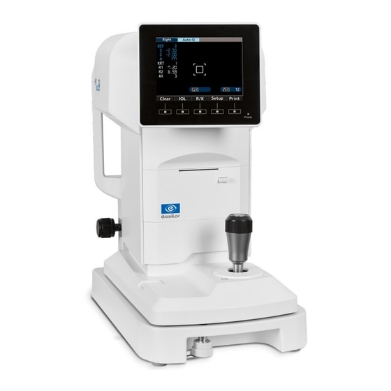
> IV. D SER MANUAL EVICE 1. G ENERAL DESCRIPTION OF PRODUCT This product (AKR550) aims to objectively measure the refractive power of the eye by using the light that is projected to and reflected from the eyeground. It also aims to measure the radius of corneal curvature by using the light that is projected to and reflected from the cornea. -
Page 17: Usage Of Product
> IV. D SER MANUAL EVICE Degree of protection against harmful intrusion of water (IEC 60529): IPX0 This product does not provide protection against intrusion of water. (The degree of protection against harmful ingress of water defined in IEC 60529 is IPX0). Classification by safety of use in air/ flammable anesthetic gas, oxygen or nitrous oxide/ flammable anesthetic gas atmosphere: •... -
Page 18: Parts Identification
> IV. D SER MANUAL EVICE 7. P ARTS IDENTIFICATION 1. LCD monitor 2. Power indicator 3. Printer unit 4. Base unit 5. Slide lock 6. Operation switch 1. Headrest 2. Eye mark 3. Chinrest 4. Rating plate 5. Power inlet 6. -
Page 19: Instructions For Use
V. I NSTRUCTIONS FOR USE... -
Page 20: Conveyance
> V. I SER MANUAL NSTRUCTIONS FOR USE 1. C ONVEYANCE 1. Before conveyance, move the main unit undermost, set it in the center of the base unit and secure it by tightening the slide lock. Side of examiner Side of examinee 1. -
Page 21: Connection / Wiring
> V. I SER MANUAL NSTRUCTIONS FOR USE 3. C ONNECTION IRING 1. Connect the earth cable of the power cord to the earth terminal. 2. Do not damage the power cord (folding it small, pulling it or putting a heavy object on it etc.). Also, do not remodel it. -
Page 22: Disposal
> V. I SER MANUAL NSTRUCTIONS FOR USE 5. D ISPOSAL To avoid potential damage to the environment and possibly human health, this device should be disposed of (i) for EU member countries – in accordance with WEEE (Directive on Waste Electrical and Electronic Equipment), or (ii) for all other countries, in accordance with a local disposal and recycling laws. -
Page 23: How To Use
VI. H OW TO USE... -
Page 24: Operation Procedure
> VI. H SER MANUAL OW TO USE 1. O PERATION PROCEDURE The operation switches under the monitor correspond to the icons displayed on the bottom of the monitor. For usual measurement, the operating switches correspond to the icons as shown below. 1. -
Page 25: Measurement Flow
> VI. H SER MANUAL OW TO USE 2. M EASUREMENT FLOW Procedure Process Reference section Relevant section Prepare for measurement 6.3.1 Power distribution 6.3.2 Ask an examinee to ready for a 6.4 Setting of etup screen measurement 6.3.4 7.2 Fuse replacement 7.3 Setting of chinrest liner Alignment 6.3.5... -
Page 26: Measurement
> VI. H SER MANUAL OW TO USE 3. M EASUREMENT a. Preparation for measurement 1. Main unit 2. Slide lock 3. Base unit 1. Do not place the device at where outside light exposes it directly from the examinee side. 2. -
Page 27: Standby
> VI. H SER MANUAL OW TO USE c. Standby When the power is turned on, the screen as shown below appears on the LCD monitor, which is ready for the measurement. 1. Indication of right eye 2. Measurement start method 3. -
Page 28: Preparation Of Examinee
> VI. H SER MANUAL OW TO USE d. Preparation of examinee 1. Clean the chinrest and dispose one chinrest liner on the top. Clean the chinrest with the neutral cleanser when there is no chinrest liner. For disinfecting the chinrest, use the ethanol. •... - Page 29 > VI. H SER MANUAL OW TO USE In case of Auto Quick or Auto It starts measurement automatically when it brings the subject eye into focus. 1. Look for the subject eye by operating the joystick. The Kerato ring appears as bringing it into focus. If the eyelid is over the Kerato ring, urge the examinee to open his/her eye wider.
- Page 30 > VI. H SER MANUAL OW TO USE 3. Operate the joystick so as to bring it into focus as aligning the alignment mark (+) with the center of the reticle mark. The measurement is started when alignment is achieved and the mark of the measurable minimum pupil diameter is changed to green.
- Page 31 > VI. H SER MANUAL OW TO USE In case of Manual 1. Look for the subject eye by operating the joystick. The Kerato ring appears as bringing it into focus. If the eyelid is over the Kerato ring, urge the examinee to open his/her eye wider. 2.
-
Page 32: Measurement
> VI. H SER MANUAL OW TO USE f. Measurement The measurement start method is different depending on the setting. Setting Measurement start method The measurement is started automatically when The setting of Start is either “Auto-Quick” or “Auto” alignment is achieved. Start the measurement by pressing the start switch The setting of Start is “Manual”... -
Page 33: Print-Out Of Measurement Result
> VI. H SER MANUAL OW TO USE g. Print-out of measurement result The measurement result can be printed out by pressing the print switch after the measurements. A maximum of the data for each eye can be saved and the most reliable value among them is indicated as the optimum value. - Page 34 > VI. H SER MANUAL OW TO USE <Sample of Printout 2> Print REF/KRT setting: All Message area No. of examinee Data of right eye Refractive data Photopic pupil size Optimum values of the refractive measurement results They are indicated when more than 3 times of measurements are taken for each eye Spherical equivalent Scotopic pupil size Kerato data...
-
Page 35: Setting Of Setup Screen
> VI. H SER MANUAL OW TO USE Optimum values of the corneal curvature radius They are indicated when more than 3 times of measurements are taken for each eye Residual astigmatism PD for far vision PD for near vision Message area It can print out the registered characters in the range of 24 characters/line ×... - Page 36 > VI. H SER MANUAL OW TO USE Details of each setting item - [Screen 1] • Step: Select the step for refractive measurement. • VD: Select the corneal vertex distance. • IOL: Select the function of the operation switch. ◦...
- Page 37 > VI. H SER MANUAL OW TO USE Details of each setting item - [Screen 2] • SE: Set the output of SE value. ◦ On: Output the representative value of SE on print-out, data screen and communication output (XML format only). ◦...
-
Page 38: Number
> VI. H SER MANUAL OW TO USE a. Number This function can set or change the number of the examinee, and select if displaying the number on the monitor and the printout. • Set: Set/change the number of the examinee. (Maximum of 5 digits can be input). -
Page 39: Language
> VI. H SER MANUAL OW TO USE b. Language This function can select the language displayed on the screen. Selectable language: EN (English), CN (Chinese), FR (French), ES (Spanish), PT (Portuguese), IT (Italian), GE (German). 1. Move the cursor to the item to be set by pressing and execute it by pressing 2. -
Page 40: Date Form
> VI. H SER MANUAL OW TO USE d. Date form Select the display format of the date from the followings: • YMD: Display the date as year/ month/day. • DMY: Display the date as day/month/year. • MDY: Display the date as month/day/year. The screen above appears when selecting “YMD”... -
Page 41: Message
> VI. H SER MANUAL OW TO USE e. Message This function is to input the message in the range of 24 characters/line × 2 lines and output it. The message input screen appears by selecting “On” and pressing 1. Select the characters by pressing and input them by pressing A space can be input by pressing 2. -
Page 42: Scotopic Pupil Size (Sps) - Measurement Function
> VI. H SER MANUAL OW TO USE 5. S (SPS) - COTOPIC UPIL MEASUREMENT FUNCTION This function is to measure the pupil size of the subject eye in the dark. Switch to the SPS measurement by pressing the measurement mode switch on the front panel. When measuring the scotopic pupil size, darken the room. -
Page 43: Iol Measurement Function
> VI. H SER MANUAL OW TO USE 6. IOL MEASUREMENT FUNCTION When measuring the IOL (intraocular lens) implanted eye, the eye with a cataract, or the eye with the scratches on the cornea, the measurement errors may occur and it is difficult to complete the measurement with REF measurement. - Page 44 > VI. H SER MANUAL OW TO USE Example of printout Example of data screen output “I” is indicated on the left of the measurement value when measuring it in the IOL measurement mode. The IOL measurement mode is canceled by performing one of the followings: 1.
-
Page 45: Low Reliability Mark Display Function
> VI. H SER MANUAL OW TO USE 7. L OW RELIABILITY MARK DISPLAY FUNCTION This device has the low reliability mark display function. The low reliability mark is displayed on the measurement result which reliability is low when taking the refractive measurement with this function activated. -
Page 46: Data Screen Function
> VI. H SER MANUAL OW TO USE Contact your local distributor about operation, connection method and output data etc. The instruments which are connected to this device by RS-232C should comply with the safety standard of IEC60601-1. Do not touch the external connection terminal and examinee at the same time. It may cause electric shock. - Page 47 > VI. H SER MANUAL OW TO USE 2. It is displayed as shown by pressing the print switch after the measurement. In case that the setting of “Auto Print” is “On”, it is displayed as shown on the left after completing the measurement.
-
Page 48: Power Saving Function
> VI. H SER MANUAL OW TO USE 10. P OWER SAVING FUNCTION The power saving function is activated when leaving it on without any switch operations. (Refer to “Save (min.)” of “6.4 Setting of Setup Screen” about the selection of the power saving function.) The measurement mode is activated by pressing the switch (the switch on the front panel of the measurement start switch). -
Page 49: Storage And Maintenance
VII. S TORAGE AND MAINTENANCE... -
Page 50: Reload Of Printer Paper
> VII. S SER MANUAL TORAGE AND MAINTENANCE Do not perform any maintenance when used with a patient. 1. R ELOAD OF PRINTER PAPER Push on the printer door button to open the printer paper cover. Pay attention to the direction of the paper rolled and set it in. Set the paper as coming out toward the front from the upside. -
Page 51: Fuse Replacement
> VII. S SER MANUAL TORAGE AND MAINTENANCE 2. F USE REPLACEMENT Unplug the power cord from the unit before removing the fuse holder. You may be in danger of electric shock if removing the fuse holder without unplugging the power cord. When a fuse is blown, remove the fuse holder from the device for replacement. -
Page 52: Storage Of Device
> VII. S SER MANUAL TORAGE AND MAINTENANCE 4. S TORAGE OF DEVICE 1. Points to check for long-term storage ◦ Turn off the power ◦ Remove the power cord from the outlet ◦ Place the main unit undermost ◦ Secure the main unit by locking the slide lock of the main unit ◦... -
Page 53: Periodical Inspection And Maintenance
> VII. S SER MANUAL TORAGE AND MAINTENANCE Model eye Setting of model eye • Remove the contact lens holder and set the model eye carefully not to incline back and forth and around.It cannot take CYL value data correctly if the model eye is inclined. •... -
Page 54: Viii. T Ips For Effective Measurement
VIII. T IPS FOR EFFECTIVE MEASUREMENT... -
Page 55: Tips For Effective Measurement
> VIII. T SER MANUAL IPS FOR EFFECTIVE MEASUREMENT 1. Do not allow external light to directly penetrate the room. 2. Fluctuation of the measurement values may occur if the examinee looks something other than the target. Urge the examinee to concentrate on the target set in front. 3. -
Page 56: Error Display
IX. E RROR DISPLAY... -
Page 57: Ix. E Rror Display
> IX. E SER MANUAL RROR DISPLAY This device automatically evaluates measurement condition or result and indicates error messages if it is invalid. An error messages also appear when abnormality is detected in its operational system. When any error messages appear, always check the system with a supplied model eye. If it appears when no abnormality in system is detected, check the measured eye for eye diseases or problems. -
Page 58: X. M Ain Trouble And Troubleshooting
X. M AIN TROUBLE AND TROUBLESHOOTING... -
Page 59: Main Trouble And Troubleshooting
> X. M SER MANUAL AIN TROUBLE AND TROUBLESHOOTING If a malfunction is found, refer to the table below to take the appropriate measures. Never disassemble, modify or repair the device. It can result in electrical shock. Symptoms Causes and measures •... -
Page 60: Specifications
XI. S PECIFICATIONS... - Page 61 > XI. S SER MANUAL PECIFICATIONS In case of VD=12 Sphere (S): -30D to +22D Step: 0.12/0.25D Refractive measurement range Cylinder (C): 0 to ±10D Step: 0.12/0.25D Axis angle (A): 1 to 180° Step: 1° Radius of curvature: 5.0 to 10.0 mm Step: 0.01mm Corneal refractive n=1.3375 Corneal power: 33.75 to 67.5D Corneal curvature radius...
- Page 62 Essilor Instruments USA 8600 W. Catalpa Avenue, Suite 703 Chicago, IL 60656 Phone: 855.393.4647 Email: info@essilorinstrumentsusa.com www.essilorinstrumentsusa.com...
Need help?
Do you have a question about the AKR 550 and is the answer not in the manual?
Questions and answers