Haulotte SUMMIT SERIES Operator's Manual
Hide thumbs
Also See for SUMMIT SERIES:
- Instructions (4 pages) ,
- Instructions (4 pages) ,
- Parts and service manual (117 pages)

Related Manuals for Haulotte SUMMIT SERIES


Summary of Contents for Haulotte SUMMIT SERIES
- Page 1 Operator's manual Operator's manual SUMMIT SERIES 3632T - HTT13 3522A - HTA13P - 4527A - HTA16P - 5533A - HTA19P 24203 0 2420341380 E 02.12...
-
Page 2: Table Of Contents
3 - Warranty - New product - HAULOTTE® North America ......4 - Warranty claims procedure ..... . . - Page 3 Operator's manual EQUIPMENT MAINTENANCE 1 - Battery recharge ....... . 2 - Daily service checks.
- Page 4 Operator's manual OPTIONAL EQUIPMENT 1 - Drive and set ........2 - Drive and set safety .
-
Page 5: Aerial Work Platform
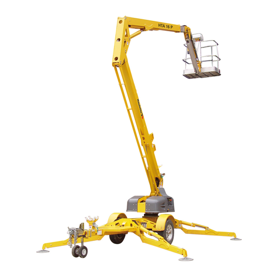
Check local requirements with your manager. HAULOTTE Group is dedicated to the continuous improvement of this and all HAULOTTE Group products. Therefore, equipment information is subject to change without notice. Direct any questions or concerns regarding errors and / or discrepancies in this manual to the HAULOTTE Group Service Department. - Page 6 Summit Series 3522A (HTA13P) - 4527A (HTA16P) - 5533A (HTA19P) Platform Jib boom Extension boom Secondary boom Knuckle Master cylinder Lower link Primary lift cylinder Outrigger cylinder Outrigger leg Axle 2420341380 E 02.12...
- Page 7 Summit Series Outrigger foot Outrigger pad Primary boom rest Latch release Dolly wheel Trailer hitch Coupler Jack Generator interface plate Turntable Secondary boom rest Primary boom Secondary lift cylinder Slave cylinder Jib lift cylinder 2420341380 E 02.12...
-
Page 8: Safety
Summit Series - Safety Safety Proper training is required for the safe operation of any mechanical device. Failure to follow all instructions and safety precautions in this manual and attached to the aerial work platform will result in death or personal injury. -
Page 9: Before Operation
Keep loose clothing, jewelry, gloves and hair away from moving parts. • ALWAYS wear a Safety Harness and energy-absorbing Lanyard, such as the Safety Harness and Lanyard available through the HAULOTTE Group. • ALWAYS inspect platform floor and outrigger footpads for mud, grease, debris or other foreign material. -
Page 10: During Operation
Summit Series - Safety 3 - During operation Ensure the following general safety precautions are followed while operating the Aerial Work Platform : • ALWAYS position away from power lines, this ensures that no part of the aerial work platform accidentally reaches into an unsafe area. - Page 11 • NEVER exceed the load limits set by the manufacturer / factory. Use only the material lifting hook, supplied as an option and manufactured by Haulotte Group when lifting materials. Safely stow all tools and equipment. • NEVER exceed load ratings by transferring loads to the aerial work platform at elevated heights.
-
Page 12: Drive Safety
Summit Series - Safety • NEVER modify the platform or carry materials that would increase the surface area of the platform. Increasing the area exposed to the wind may affect the aerial work platform stability. NEVER attach overhanging loads when raising or lowering the platform. -
Page 13: Fall Protection
Summit Series - Safety 5 - Fall protection • Occupants must wear a safety belt or harness in accordance with all Federal, State, and Local codes and regulations. Attach lanyard to the anchor provided on the work platform. • NEVER sit, stand, or climb on the platform guard rails. Maintain a firm footing on the platform floor at all times. -
Page 14: Wind Loading
Summit Series - Safety Wind loading • Never operate the aerial work platform in strong or winds that exceed 28 mph (12.5 m/s) or 45 km/h. Never increase the surface area of the platform or the load. Increasing the area exposed to the wind will decrease the aerial work platform stability. -
Page 15: Explosion Hazard
Summit Series - Safety 8 - Explosion hazard • NEVER operate aerial work platform if you smell or detect Liquid Petroleum Gas (LPG), gasoline, diesel fuel or other explosive substances. • ALWAYS charge Batteries only in an open, well-ventilated area away from sparks, flames and lighted tobacco. -
Page 16: Maintenance
• NEVER adjust, repair, replace or bypass any hydraulic or electrical control or safety device. These include, but are not limited to; hydraulic load control and flow control valves, solenoid valves and limit switches. ALWAYS consult an authorized HAULOTTE Group technician by contacting the Customer Service Department at 1-800-537-0540 if repairs are necessary. -
Page 17: Battery Maintenance
Summit Series - Safety • NEVER modify, alter or change the aerial work platform without first consulting an authorized HAULOTTE Group technician, and NEVER in any way that would affect its original design or operation. 9.2 - BATTERY MAINTENANCE Ensure the following general safety precautions are followed when performing battery maintenance on the aerial work platform : •... -
Page 18: Specifications
Summit Series - Specifications 3522A (HTA13P) 2420341380 E 02.12... - Page 19 Summit Series - Specifications Technical characteristics-For 3522A (HTA13P) Machine 3522A (HTA13P) Metric Characteristics Imperial Maximum work height 12.73 m(41 ft9 in) Maximum platform height 10.90 m(35 ft9 in) Up and over height 5.79 m(19 ft0 in) • From centerline : 6.86 m(22 ft6 in) Maximum horizontal outreach •...
- Page 20 Summit Series - Specifications Machine 3522A (HTA13P) Metric Characteristics Imperial Primary boom : • Primary, up - Fast : 14-18 sec • Primary, up - Slow : 33-37 sec • Primary, Down - Fast : 14-18 sec • Primary, Down - Slow : 46-60 sec Secondary boom : •...
-
Page 21: Operation
The Haulotte Telescoping Boom Lift model(s) 3632T (HTT13) and Articulating Boom Lift model(s) 3522A-4527A-5533A (HTA13-16-19P) are Summit Series trailer-mounted aerial work platforms, designed and manufactured to position per- sonnel with their tools and equipment at overhead work locations. The platform load capacity is rated at 227 kg(500 lb). -
Page 22: Ground (Lower) Control Panel
Summit Series - Operation Ground (lower) control panel-Articulating model(s) Marking Description Function Key Switch Turning the KEY SWITCH ( 1 ) counter clockwise to the GROUND ( 1a ) icon selects operation from the ground Ground Controls Position (lower) control panel. - Page 23 Summit Series - Operation Marking Description Function The DISPLAY PANEL is a lighted text window that displays the current operating status or an existing error condition Display panel when the KEY SWITCH ( 1 ) is positioned at either ( 1a ) or ( 1b ).
- Page 24 Summit Series - Operation Marking Description Function Boom rotation buttons - Clockwise Pressing (pushing) and holding a desired SPEED button ( 15 ) and the BOOM ROTATION button ( 18 ) at the same time enables the boom to rotate in the CLOCKWISE direction.
-
Page 25: Platform (Upper) Control Panel
Summit Series - Operation Platform (upper) control panel-Articulating model(s) Marking Description Function Engine start (Models with engines Start a cold engine by pressing (pushing) in and holding the only) CHOKE ( 2 ) button then press (push) the ENGINE START ( 1 ) button. - Page 26 Summit Series - Operation Marking Description Function Indicator LEDs light up to indicate the level of charge in the batteries : • A lighted green LED indicates an adequate charge level. Battery condition indicator • A lighted yellow LED indicates the need for charging soon.
- Page 27 Summit Series - Operation Marking Description Function Boom raise button Pressing (pushing) and holding a desired SPEED button ( 6 ) and the BOOM RAISE button ( 9 ) at the same time will raise the boom. Pressing (pushing) and holding a desired SPEED button ( 6 )
- Page 28 Summit Series - Operation Releasing travel latches-Articulating model(s) : • Release both travel latches, ( 1 ) the primary latch on the boom rest, and ( 2 ) the secondary latch on the Primary Boom, by raising the latch handle and swinging the clasp down.
- Page 29 Summit Series - Operation Outrigger Control Panel • Verify that the AUTO LEVEL ( 23 ) indicator LED is lit. If the AUTO LEVEL ( 23 ) indicator is not lit, the aerial work platform may not be level, and the weight of the machine may not be on the outrigger foot pad.
- Page 30 Summit Series - Operation • Turn the key switch to the GROUND CONTROL ( 1a ) position. • Unfasten the safety harness and exit the platform by using a 3 point contact (both hands and one foot). Telescopic model(s) : •...
-
Page 31: Manual Boom Operation
Summit Series - Operation 4 - Manual boom operation Manual retraction, rotation and lowering functions allow the boom(s) to be moved and lowered during hydraulic power interruption or failure. The following procedures for manual retraction, rotation and lowering require a person on the ground to operate the manual controls and hand pump. -
Page 32: Manual Rotation
Summit Series - Operation 4.2 - MANUAL ROTATION To rotate the TURNTABLE clockwise : • Push and hold the ROTATION button IN. • Simultaneously actuate the HAND PUMP. To rotate the TURNTABLE counterclockwise : • Pull the ROTATION button OUT. -
Page 33: Manual Boom Lowering Procedure-Articulating Model(S)
Summit Series - Operation 4.4 - MANUAL BOOM LOWERING PROCEDURE-ARTICULATING MODEL(S) Each lift cylinder is equipped with a MANUAL LOWERING VALVE, found at the base of each lift cylinder. Use the VALVE to lower the platform in case of a complete electrical power failure, a load shift, or any other emergency. - Page 34 Summit Series - Operation Location of manual lowering valves 1 : Turntable Primary lift cylinder 2 : Valve "push" button 1 : Knuckle Secondary lift cylinder 2 : Valve "push" button Jib lift cylinder 1 : Valve "push" button 2420341380...
-
Page 35: Towing The Aerial Work Platform
Summit Series - Operation 5 - Towing the aerial work platform The aerial work platform trailer includes a single axle, two-inch ball hitch, hydraulic surge brakes, mechanical parking brake, safety chains, brake lights and side marker lights. Proper aerial work platform transport requires the proper attachment and inspection of these components before towing. -
Page 36: Hitch And Tow Procedure
Summit Series - Operation 6 - Hitch and Tow procedure Back the tow vehicle to the trailer. Verify that the ball and trailer hitch are aligned and that the trailer hitch has proper clearance above the ball. Trailer hitching Marking... -
Page 37: Lifting The Aerial Work Platform
Summit Series - Operation 7 - Lifting the aerial work platform • Completely retract and lower all booms into the "stowed" position. • Secure both boom travel latches ( A ). • Remove all loose materials from machine. • Retract all outriggers cylinders to fully "stowed" (upright) position. -
Page 38: Transporting The Aerial Work Platform On To A Truck Bed
Summit Series - Operation 8 - Transporting the aerial work platform on to a truck bed • Verify that the truck or trailer is parked on a firm and level surface. • Completely retract and lower all booms into the "stowed" position. -
Page 39: Equipment Maintenance
Refer to it when inspecting this machine. It is the practice of HAULOTTE Group to issue Service and / or Safety Bulletins, which may include updates to the in- formation contained in this manual. In such instances, procedures contained in Haulotte Group Service Bulletins or Safety Bulletins supersede the information contained in manual. -
Page 40: Battery Recharge
Summit Series - Equipment Maintenance 1 - Battery recharge Recharge aerial work platform batteries after each 8 hour work shift or as needed. . When the aerial work platform is not in use, batteries should be recharged at least once per week. Under normal circumstances, battery recharge should take approximately 10-12 hours. - Page 41 Summit Series - Equipment Maintenance Do not disconnect any output leads or connectors between the batteries and the charger when the charger is on. To stop a charge in progress, always unplug the extension cord from the AC power source.
-
Page 42: Daily Service Checks
Summit Series - Equipment Maintenance 2 - Daily service checks The following maintenance procedures should be performed daily or before each operation : • Verify that all decals are legible, correctly applied, and in plain view. "Decal Replacement" section of this manual for decal locations. - Page 43 Summit Series - Equipment Maintenance • Verify that the boom / jib limit switches operate correctly : • Limit switches are actuated when the primary, secondary and jib booms are in the fully lowered "stowed" position. Limit switches must be activated to raise or lower outriggers.
- Page 44 Summit Series - Equipment Maintenance • Inspect hydraulic system and fluid levels : • Check all hydraulic hoses and fittings for leaks and / or damage. Tighten or replace as necessary to prevent hydraulic oil or pressure loss • The hydraulic oil level should be checked with the booms down, all outriggers raised, and in the "stowed"...
-
Page 45: Weekly Service Checks
Summit Series - Equipment Maintenance 3 - Weekly service checks Perform the following service checks at least once each week in addition to all recommended daily service checks : • Check Battery electrolyte level. • If battery charge is low, add enough water to bring the electrolyte level to the top of the plates. -
Page 46: Monthly Service Checks
Summit Series - Equipment Maintenance 4 - Monthly service checks Perform the following service checks at least once each month in addition to all recommended daily and weekly service checks : • Clean all battery terminals. • Check battery for loose connections or damaged wires. -
Page 47: Annual Service Checks
• Follow all manufacturer's recommendations when making repairs to critical components. • Personnel making repairs to welds should be certified in accordance with the Structural Welding Code AWS D1 and Haulotte design standards. Inspect outriggers for wear or damage. Repair or replace as necessary. - Page 48 Summit Series - Equipment Maintenance Inspect and adjust axle and parking brakes Load test telescoping boom lift operations with 227 kg (500 lb) load. Machines equipped with Platform Rotator, must be tested with 200 kg (440 lb). Replace Jib Bushings : •...
- Page 49 • Rotate the platform 180° and re-record the measurement. • If the difference in measurements is greater than 6.35 mm (0.25 in) the slew ring bearing should be replaced. Contact Haulotte Group Customer Service Department: at 1-800-537-0540 or visit Haulotte Group online at www.haulotte-usa.com for additional information.
-
Page 50: Structural Inspection
7 - Motor drying instructions Inclusion of water or foreign particles into the DC electric motor housing may cause serious damage to the motor. If the motor becomes wet, follow these instructions or contact an authorized Haulotte Group service technician : •... -
Page 51: Leveling System Calibration Procedure
Summit Series - Equipment Maintenance 8 - Leveling system calibration procedure 8.1 - MACHINE LEVELLING INSTRUCTIONS Deploy all of the outriggers, and slightly raise the base of the machine to position it for leveling. Place a small, standard "level" on the base of the turntable (Level Placement Option A). If a small "level"... - Page 52 Summit Series - Equipment Maintenance If your level sensor resembles the image in Figure ( B ) ( p e n d u l u m b a s e d l e v e l s e n s o r ) , f o l l o w t h e s e instructions.
-
Page 53: Ground (Lower) Control Box Calibration Instructions
Summit Series - Equipment Maintenance 8.3 - GROUND (LOWER) CONTROL BOX CALIBRATION INSTRUCTIONS Use the ground (lower) control panel to access the control box maintenance menu. Ground (Lower) Control Panel for Leveling System Verify that the KEY SWITCH ( 1 ) is turned to the GROUND ( 1A ) icon, and that both EMER- GENCY STOP ( 2 ) buttons (ground and platform) are "pulled out". -
Page 54: Overload Protection Calibration Procedure
Summit Series - Equipment Maintenance 9 - Overload protection calibration procedure 9.1 - LOAD SENSE ZEROING Remove the CLEVIS PIN securing the PLATFORM to the PLATFORM MOUNTING BRACKET, allowing the PLATFORM to pivot about the PLATFORM PIN and rest on the ground. This re- moves the load from the LOAD CELL. - Page 55 Summit Series - Equipment Maintenance Ground (lower) control panel for overload protection 2420341380 E 02.12...
-
Page 56: Load Sense Scaling
Summit Series - Equipment Maintenance 10 - Load Sense Scaling Return the platform to the upright position and re-install the CLEVIS PIN. Exit the maintenance mode by scrolling through the menu using the TURTLE ( 7 ) button. Press (push) the PLATFORM TILT UP ( 4A ) button and PLATFORM TILT DOWN ( 4B ) button simultaneously to display the platform's weight ( +/- 10% ) in the DISPLAY PANEL ( 3 ). -
Page 57: Additional Service Information
The Ratio should be within 3.50:1 to 4.00:1. If so, continue on to Step 11. If the ratio is not within the above values, contact Haulotte Group Cus- tomer Service Department: at 1-800-537-0540 or visit Haulotte Group online at www.haulotte- usa.com. -
Page 58: Manual Outrigger Retraction
Summit Series - Equipment Maintenance 12 - Manual outrigger retraction The Manual Outrigger Retraction procedure allows the outriggers to be retracted into the "stowed" (upright) position during hydraulic power interruption or power failure. The Manual Outrigger Control Kit, Part Number: A-00819, including a wire harness, is required to perform this manual procedure. - Page 59 Summit Series - Equipment Maintenance Bottom Side of the Ground (lower) Control Box Reference Description of the components Outrigger wire harness Hydraulic Power Unit Reference Description of the components Valve C7 Pump handle receptacle Proportional valve 2420341380 E 02.12...
-
Page 60: Hydraulic Pressure Gauge
Summit Series - Equipment Maintenance 13 - Hydraulic pressure gauge The Hydraulic Pressure Gauge Part Number B02-16-0020 is used to measure the aerial work platform's system pressure. It is used as a diagnostic tool when the Boom is NOT performing as expected. -
Page 61: Troubleshooting
- Equipment Maintenance 14 - Troubleshooting Refer to the following table for basic troubleshooting operations. Contact Haulotte Group Customer Service Department at 1-800-537-0540 or visit Haulotte Group online at www.haulotte-usa.com with any questions or before attempting any advanced troubleshooting operations. -
Page 62: Error Code Definitions-Controls
If an error condition is detected, the appropriate error code will be displayed on this panel. Refer to Table following paragraph to resolve the error Or Contact Haulotte Group Customer Service Department: at 1-800-537-0540 or visit Haulotte Group online at www.haulotte-usa.com for any additional questions. - Page 63 Summit Series - Equipment Maintenance 009 BOOM Lower Control has Disconnect a wire from This is a self clearing UP WITHOUT detected the boom is up either the boom down error. When error OUTRIGGER and all four outriggers or any outrigger switch...
- Page 64 Summit Series - Equipment Maintenance Load Sense Module 019 BOOM has detected an This is a latched error. Machines with Load FUNCTION overloaded boom and Overload Boom Power must be cycled Sense option only DISABLED disabled boom to clear error.
- Page 65 Summit Series - Equipment Maintenance A load of less than 70 031 OPEN This is a latched error. Checked only at power mA was detected when Disconnect a wire from CIRCUIT JIB Power must be cycled up Articulating Boom Jib Down circuit was...
- Page 66 Summit Series - Equipment Maintenance 043OPEN A load of less than 70 This is a latched error. Checked only at power CIRCUIT mA was detected when Disconnect a wire from Power must be cycled up Articulating Boom PLATFORM Platform CCW circuit Platform CCW coil to clear error.
- Page 67 Summit Series - Equipment Maintenance 056SHORTE Excessive load was Use a piece of wire to This is a latched error. D CIRCUIT detected when RF Checked only at power short the RF Outrigger Power must be cycled Outrigger circuit was coil to clear error.
- Page 68 Summit Series - Equipment Maintenance 069OPEN A load of less than 70 This is a latched error. CIRCUIT mA was detected when Disconnect a wire from Checked only at power Power must be cycled PROPORTIO Proportional circuit was Proportional coil to clear error.
- Page 69 Summit Series - Equipment Maintenance 081OPEN A load of less than 70 Checked only at power This is a latched error. CIRCUIT mA was detected when Disconnect a wire from Power must be cycled DRIVE Drive Enable circuit Drive Enable coil Machines with Drive to clear error.
- Page 70 Summit Series - Equipment Maintenance 094SHORTE Excessive load was Checked only at power Use a piece of wire to This is a latched error. detected when Forward CIRCUITFOR short the Forward 2 ( Power must be cycled 2 ( C27) circuit was...
- Page 71 Summit Series - Equipment Maintenance Cylinder safety 106OUTREA This is a latched error. pressure switch has Disconnect safety Machines with Moment CH SENSING Power must be cycled detected maximum pressure switch wires Sense option only FAULT to clear error. pressure setting...
- Page 72 Summit Series - Equipment Maintenance 129OPEN A load of less than 70 Checked only at power This is a latched error. CIRCUIT FS mA was detected when Disconnect a wire from Power must be cycled EXT (FWS FS Ext (FWS C25)
- Page 73 Summit Series - Equipment Maintenance 142SHORTE Excessive load was Checked only at power Use a piece of wire to This is a latched error. D CIRCUIT detected when DC D short the DC D (FWS Power must be cycled DC D (FWS...
- Page 74 Summit Series - Equipment Maintenance 155OPEN A load of less than 70 Checked only at power This is a latched error. CIRCUIT mA was detected when Disconnect a wire from Power must be cycled (FWS SPARE (FWS SPARE 1) circuit...
-
Page 75: Error Code Definitions - Motor Controller
Figure Motor controller for a visual of the controller. Table "Error code definitions - Motor controller" to resolve the Fault, or contact Haulotte Group Customer Service Department: at 1-800-537-0540 or visit Haulotte Group online at www.haulotte- usa.com with any questions. - Page 76 Summit Series - Equipment Maintenance Error code definitions - Motor controller Flash fault Priority ID Fault Description Solution Steady ON, no System is operating None None required flashing normally One or more controller Configuration Use Sevcon calibrator to enter correct...
- Page 77 Summit Series - Equipment Maintenance Recycle power. If fault repeatedly Maximum power occurs, look for binding on the available to pump Pump ITT Current hydraulic cylinders or sticking valves. motor has been Limit Cutback If fault repeatedly occurs, look for...
- Page 78 Summit Series - Cylinder replacement Cylinder replacement 1 - Master / slave cylinder replacement - Articulating models Use the following procedure to remove and replace faulty cylinders. 1.1 - MASTER CYLINDER • With the boom in the "stowed" position, raise the upper boom until there is adequate exposure of the pin retainer and pivot pin.
- Page 79 Summit Series - Cylinder replacement 1.2 - SLAVE CYLINDER • With the boom in the "stowed" position, extend the telescoping boom until there is adequate exposure of the pin retainer and pivot pin (Approximately 0.7 m (2 ft)). • Verify that the upper boom is supported by lifting straps and an overhead hoist or equivalent.
- Page 80 Summit Series - Cylinder replacement 1.3 - LIFT CYLINDER REPLACEMENT - ARTICULATING MODELS HLA16PX, 45XA, HLA19PX, 55XA, HTA13P, 3522A, HTA16P, 4527A, HTA19P, 5533A Aerial Work Platforms have three (3) lift cylinders, use the following procedure to remove and replace faulty or damaged hydraulic cylinders.
- Page 81 Summit Series - Cylinder replacement location of manual lowering valves for lift cylinder replacement - Jib lift cylinder Reference Description of the components Valve "push button" • With the boom in the "stowed" position, press (push) in and hold the emergency lowering valve "button"...
- Page 82 Summit Series - Cylinder replacement Lift cylinder replacement Reference Description of the components Cylinder Pin retainer Piston end Base end • Verify that the cylinder is supported by lifting straps and an overhead hoist or equivalent. • Remove the pivot pin using a hammer and a brass or hardwood drift.
- Page 83 Summit Series - Cylinder replacement 2 - Master / slave cylinder replacement - Telescopic models Use the following procedure to remove and replace faulty cylinders. 2.1 - MASTER CYLINDER • With the boom in the "stowed" position, raise the boom until there is adequate exposure of the pin retainer and pivot pin.
- Page 84 Summit Series - Cylinder replacement • Bleed trapped air from the hydraulic system by raising and lowering the telescoping boom with the reservoir fill port cap on, but not tightened. Allow several cycles of operation for trapped air to escape.
- Page 85 Summit Series - Cylinder replacement 3 - Lift cylinder replacement - Telescopic models Use the following procedure to remove and replace a faulty or damaged hydraulic cylinder on the aerial work platform : • Lower the boom until it is resting in the "stowed" position.
- Page 86 Summit Series - Cylinder replacement Lift cylinder replacement Reference Description of the components Pin retainer Cylinder Piston end • Lift and remove the cylinder using an overhead hoist and lifting straps or equivalent. • Replace or reinstall the cylinder by following the above instructions in the reverse order of removal.
- Page 87 Summit Series - Cylinder replacement 4 - Outrigger cylinder replacement Use the following procedure to remove and replace faulty or damaged hydraulic cylinders on theoutriggers : • Lower the outrigger until the footpad is touching the ground. DO NOT transfer the weight of the aerial work platform onto the outrigger.
- Page 88 Summit Series - Cylinder replacement Cylinder valve removal • At the base of the cylinder, unbolt and remove the pin retainer from each side of the pivot pin. • Remove the pivot pin using a hammer and a brass or hardwood drift.
- Page 89 Summit Series - Decals replacement Decal Replacement - Decal kit - ANSI standard - Articulating aerial work platform 2420341380 E 02.12...
- Page 90 B06-00-0404 Decal (s) - Warning - Outrigger Crush Foot B06-00-0161b Decal (s) - HAULOTTE Biljax - 5 inBlack / Red on clear B06-00-0477 Decal (s) - Warning - Fork Lift Use Decal (s) - HTA13P - 3522A - Black clear vinyl with black...
- Page 91 Summit Series - Decals replacement Quantit Item no. Part number Description Decal (s) - Warning - Ground operation instructions - B06-00-0533 Articulating B06-00-0484 Decal (s) - Danger - Battery / Charger instruction B06-00-0543 Decal (s) - Warning - Crush hazard...
- Page 92 Summit Series - Decals replacement Identification plates and optional equipment - Articulating aerial work platform 2420341380 E 02.12...
- Page 93 Summit Series - Decals replacement Decal Replacement - Identification plate - ANSI standard - Used on all standard equimpent Item no. Part number Description Quantity B06-00-0526 Key ring tag B06-00-0524 Annual Inspection Plate B06-00-0490 VIN Plate B06-00-0499 ANSI ID Plate Decal Replacement - Decals for optional equipment - ANSI standard Item no.
- Page 94 Summit Series - Decals replacement Decal (s) - ANSIAll aerial work platforms B06-00-0533 B06-00-0534 B06-00-0403 B06-00-0551 2420341380 E 02.12...
- Page 95 Summit Series - Decals replacement Decal (s) - ANSIAll aerial work platforms B06-00-0535 B06-00-0537 B06-00-0536 3522A / HTA 13 P 5533A / HTA 19 P 4527A / HTA 16 P B06-00-0539 B06-00-0540 B06-00-0538 2420341380 E 02.12...
- Page 96 Summit Series - Decals replacement Decal (s) - ANSIOptional equipment B06-00-0529 B06-00-0527 B06-00-0528 B06-00-0553 B06-00-0497 B06-00-0485 B06-00-0488 B06-00-0547 B06-00-0487 B06-00-0486 2420341380 E 02.12...
Need help?
Do you have a question about the SUMMIT SERIES and is the answer not in the manual?
Questions and answers