Table of Contents
Advertisement
Advertisement
Table of Contents

Related Manuals for Canon AK1


Summary of Contents for Canon AK1
- Page 1 Revision 2.0 Cassette Feeding Unit-AK1 Service Manual...
- Page 2 When changes occur in applicable products or in the contents of this manual, Canon will release technical information as the need arises. In the event of major changes in the contents of this manual over a long or short period, Canon will issue a new edition of this manual.
- Page 3 Introduction Symbols Explanation Symbols Explanation Disconnect the connector. Connect the power cable. Connect the connector. Disconnect the power cable. Remove the cable/wire from the Turn on the power. cable guide or wire saddle. Install the cable/wire to the cable Turn off the power. guide or wire saddle.
-
Page 4: Table Of Contents
Contents Contents Safety Precautions....................1 Notes Before it Works Serving......................2 Points to Note at Cleaning........................2 Notes on Assembly/Disassembly......................2 1. Product Overview.....................3 Overview............................. 4 Specifications............................4 Parts Name............................4 Cross-section View..........................5 2. Technology....................... 7 Basic Configuration..........................8 Parts Configuration..........................8 Paper Path............................ - Page 5 Contents Removing the Cassette 2 Pullout Motor (M106)..................50 Removing the Cassette 3, 4 Pullout Motor (M105).................51 Removing the Cassette 2 Pickup Drive Unit..................51 Removing the Cassette 3, 4 Pickup Drive Unit..................53 Removing the Vertical Path Drive Unit....................54 5.
-
Page 6: Safety Precautions
Safety Precautions Notes Before it Works Serving....2 Points to Note at Cleaning....2 Notes on Assembly/Disassembly..2... -
Page 7: Notes Before It Works Serving
Safety Precautions Notes Before it Works Serving • At servicing, be sure to turn OFF the power source according to the specified steps and disconnect the power plug. • Be sure to disconnect the power plug on a regular basis and remove dust and dirt accumulated around the outlet with dry cloth. -
Page 8: Product Overview
Product Overview Overview..........4... -
Page 9: Overview
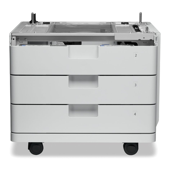
1. Product Overview Overview Specifications Item Description Paper storage method Front-loading method Pickup method Retard separation Stacking capacity 550 sheets (80 g/m2) x 3 cassettes Paper feed reference Center reference Paper size Width: 98.4 mm to 216.0 mm Length: 148.0 mm to 355.6 mm A4-R, A5-R, B5-R, LGL, LTR-R, STMT-R, EXEC-R, 16K Special paper standard size Paper weight... -
Page 10: Cross-Section View
1. Product Overview [11] [10] Parts Name Connector Cover Rear Cover Right Lower Cover [10] Cassette Right Cover [11] Right front cover Cross-section View [12] [11] [10] [13] [14] [15] Parts Name Cassette 2 pickup Roller Cassette 2 vertical path Roller Cassette 2 feed Roller Cassette 2 separation Roller Cassette 2 Liftnig Plate... - Page 11 1. Product Overview Parts Name [10] Cassette 3 Liftnig Plate [11] Cassette 4 pickup Roller [12] Cassette 4 vertical path Roller [13] Cassette 4 feed Roller [14] Cassette 4 separation Roller [15] Cassette 4 Liftnig Plate...
-
Page 12: Technology
Technology Basic Configuration....... 8 Controls..........12... -
Page 13: Basic Configuration
2. Technology Basic Configuration Parts Configuration ■ Rollers Layout drawing [10] [11] [12] Parts Name Cassette 2 pickup Roller Cassette 2 vertical path Roller Cassette 2 feed Roller Cassette 2 separation Roller Cassette 3 pickup Roller Cassette 3 vertical path Roller Cassette 3 feed Roller Cassette 3 separation Roller Cassette 4 pickup Roller... - Page 14 2. Technology ■ Sensors Layout Drawing PS101 PS104 SW101 PS110 PS107 SW104 PS102 PS105 SW102 PS111 PS108 PS103 PS106 SW103 PS112 PS109 Parts Name Parts Name PS101 Cassette 2 Pullout Sensor SW101 Cassette 2 Size Detection Switch PS102 Cassette 3 Pullout Sensor SW102 Cassette 3 Size Detection Switch PS103...
- Page 15 2. Technology ■ Route of Drive M102 M106 M101 M105 M104 M103 Parts Name M101 Cassette 3, 4 pickup Motor M102 Cassette 2 pickup Motor M103 Cassette 3, 4 Lifter Motor M104 Cassette 2 Lifter Motor M105 Cassette 3, 4 Pullout Motor M106 Cassette 2 Pullout Motor...
-
Page 16: Paper Path
2. Technology Paper Path Pickup from Cassette 2 Pickup from Cassette 3 Pickup from Cassette 4... -
Page 17: Controls
2. Technology Controls Overview Paper inside a cassette is lifted up by the Lifter Plate. The Lifter Plate is lifted up by rotating the Cassette Lifter Motor (M103/M104). When the Pickup Roller comes into contact with the paper surface, the Cassette Pickup Motor (M101/M102) rotates to pick up the surface layer paper, and the Cassette Feed Roller and Cassette Separation Roller feed only 1 sheet of paper to the feed path. - Page 18 2. Technology OFF. (When the switch is pressed: ON) Any standard size paper of AB, inch, or AK configuration can be used. However, distinction between A5-R and STMT-R should be made manually on the check screen. Distinction between EXEC-R and 16K-R and between LTR-R and 16K-R is automatically made according to the country setting.
- Page 19 2. Technology Paper size *1 All modes AB configuration Inch configuration AK configuration ‐ A5-R ‐ ‐ STMT-R 215.9 Improper loading of pa- B5-R 257.0 Improper loading of paper ‐ EXEC-R 267.0 Improper loading of paper ‐ Improper loading of paper 16K-R 270.0 ‐...
- Page 20 2. Technology Cassette Paper Sen- Cassette Paper Surface Cassette Paper Level Sen- Paper level Display on Sensor the Control Panel Approx. 50 sheets or less The control that switches the paper level display on the Control Panel is as follows: •...
- Page 21 2. Technology Cassette Paper Sensor Cassette Paper Surface Sensor Paper Paper Cassette Paper Level Sensor Cassette Paper Sensor Cassette Paper Surface Sensor Paper Paper Cassette Paper Level Sensor ■ Paper Detection Control Paper is detected by the Cassette Size Switch, Cassette Paper Surface Sensor and Cassette Paper Sensor. The absence of paper is notified when the Cassette Paper Sensor is turned ON at the time the Cassette Size Switch is turned ON (it is detected that the cassette is in the host machine) and the Cassette Paper Surface Sensor is turned OFF (the Lifter Plate is raised to the pickup position).
- Page 22 2. Technology Cassette Paper Lifting Plate Surface Sensor Detection Lever Cassette Paper Sensor Cassette Paper Level Sensor Paper Detection Lever Paper Level Detection Lever Cassette Lifter Motor Lifter Gear Lifting Plate ■ Lifter Control ● When Cassette Is Set When the cassette is set, the Cassette Lifter Motor rotates to raise the Lifter Plate. Then, the paper is raised to the position to be picked up.
-
Page 23: Jam Detection
2. Technology Stop registration control stops the Pre-registration Roller. Paper fed by the Pre-registration Roller after being picked up from the cassette generates an arch due to being pushed against the Registration Roller which has been stopped. In order to align the image on the ITB with the paper at a specified timing, this control stops paper feed with the paper arched, aligns the image on the ITB with the paper at the specified timing, and then resumes paper feed. -
Page 24: Periodical Service
Periodical Service List of Periodical Service Works..20... -
Page 25: List Of Periodical Service Works
3. Periodical Service List of Periodical Service Works This equipment does not have any items that require periodical service. -
Page 26: Disassembly/Assembly
Disassembly/ Assembly List of Parts......... 22 Removal from the Connected Equipment ........29 External Cover System....... 33 Controller System........37 Pickup Feed System......38... -
Page 27: List Of Parts
4. Disassembly/Assembly List of Parts External View [11] [10] Key No. Parts Name Cassette Front Upper Cover Cassette Front Upper Tray Cover Cassette Front Middle Tray Cover Cassette Front Lower Tray Cover Cassette Front Lower Cover Left Cover Connector Cover Rear Cover Right Lower Cover [10]... -
Page 28: List Of Main Unit
4. Disassembly/Assembly List of Main Unit [13] [12] [10] [11] Key No. Parts Name Cassette Right Cover Cassette 2 Pickup Unit Cassette 3 Pickup Unit Cassette 4 Pickup Unit Cassette 4 Auto Close Unit Cassette 3 Auto Close Unit Cassette 2 Auto Close Unit Cassette 2 Pickup Drive Unit Vertical Path Drive Unit [10]... -
Page 29: Electrical Components
4. Disassembly/Assembly Electrical Components ■ Motor M102 M106 M101 M105 M104 M103 Parts Name M101 Cassette 3, 4 pickup Motor M102 Cassette 2 pickup Motor M103 Cassette 3, 4 Lifter Motor M104 Cassette 2 Lifter Motor M105 Cassette 3, 4 Pullout Motor M106 Cassette 2 Pullout Motor... - Page 30 4. Disassembly/Assembly ■ Sensor PS107 PS104 PS101 PS110 PS108 PS102 PS105 PS111 PS103 PS109 PS112 PS106 Parts Name PS101 Cassette 2 Pullout Sensor PS102 Cassette 3 Pullout Sensor PS103 Cassette 4 Pullout Sensor PS104 Cassette 2 Paper Sensor PS105 Cassette 3 Paper Sensor PS106 Cassette 4 Paper Sensor PS107...
- Page 31 4. Disassembly/Assembly ■ Switch/PCB/Heater SW104 SW101 H101 UN101 SW102 SW103 Name UN101 Cassette Module Controller PCB SW101 Cassette 2 Size Detection Switch SW102 Cassette 3 Size Detection Switch SW103 Cassette 4 Size Detection Switch SW104 Cassette Right Door Open/Close Detection Switch H101 Cassette Heater...
-
Page 32: List Of Connectors
4. Disassembly/Assembly List of Connectors J5972 J5971 J5955 J5975 J5974 J5968 J652 J651 J5954 J5950 J5956 J650 J653 J5970 J5973 J No. Symbol Name Relay connec- J No. Symbol Name J650 UN101 Cassette Module Controller J5950 Connector Drawer J651 UN101 Cassette Module Controller J5939 J5971... - Page 33 4. Disassembly/Assembly J5960 J5930 J5979 J5978 J5959 J5952 J5953 J5940 J5936 J654 J5937 J655 J5935 J656 J5977 J5976 J No. Symbol Name Relay connec- J No. Symbol Name J654 UN101 Cassette Module Controller J5932 J5930 M105 Cassette 3, 4 Pullout Motor J654 UN101 Cassette Module Controller...
-
Page 34: Removal From The Connected Equipment
4. Disassembly/Assembly Removal from the Connected Equipment Procedure 1. Remove the Cassette 1[1]. 2. Remove the Cassette Front Upper Cover [1]. • 1 Claw [2] • 1 Hook [3] 3. Remove the Connecting Plate [1]. • 1 Knurled Screw [2]... - Page 35 4. Disassembly/Assembly 4. Remove the 2 Face Covers [1]. <In the case of the machine the without installed Cassette Heater Unit> • 2 Claws [2] • 2 Hooks [3] Remove the Face Cover [1]. <In the case of the machine the installed Cassette Heater Unit> •...
- Page 36 4. Disassembly/Assembly 5. Remove the 2 Connecting Plates [1]. <In the case of the machine the without installed Cassette Heater Unit> • 2 Knurled Screws [2] Remove the Connector Cover [1]. <In the case of the machine the installed Cassette Heater Unit> •...
- Page 37 4. Disassembly/Assembly 6. Disconnect the connector [1] of the Cassette Heater. <In the case of the machine the installed Cassette Heater Unit> 7. Hold the indented area [A] of the host machine and lift it down from the equipment. CAUTION: •...
-
Page 38: External Cover System
4. Disassembly/Assembly External Cover System Removing the Rear Cover ■ Procedure 1. Remove the Rear Cover [1]. • 3 Screws [2] • 4 Hooks [3] Removing the Cassette Right Cover ■ Preparation “Removing the Rear Cover” on page 33 ■ Procedure 1. - Page 39 4. Disassembly/Assembly 2. Remove the Right Lower Cover [1]. • 3 Screws [2] • 5 Hooks [3] CAUTION: Be careful not to drop the Cassette Right Cover [1] when disassembling/assembling. 3. Remove the screw [2] while supporting the Cassette Right Cover [1].
- Page 40 4. Disassembly/Assembly 4. Remove the Arm Holder [2] while supporting the Cassette Right Cover [1]. • 1 Shaft [3] • 2 Bosses [4]...
- Page 41 4. Disassembly/Assembly 5. Remove the Cassette Right Cover [1]. • 2 Shafts [2] NOTE: How to install the Arm Holder 1. Align the 2 bosses [3] of the Arm Holder with the 2 holes [A] of the Cassette Right Cover. 2.
-
Page 42: Controller System
4. Disassembly/Assembly Controller System Removing the Cassette Module Controller PCB ■ Preparation “Removing the Rear Cover” on page 33 ■ Procedure 1. Remove the Cassette Module Controller PCB [1]. • 7 Connectors [2] • 2 Screws [3] • 2 Hooks [4]... -
Page 43: Pickup Feed System
4. Disassembly/Assembly Pickup Feed System Removing the Cassette Pickup Roller / Cassette Separation Roller / Cassette Feed Roller ■ Procedure NOTE: In this procedure, the procedure for the Cassette 2 Pickup Unit [1] is described. Perform the same procedure for removing the Cassette 3 Pickup Unit [2] and the Cassette 4 Pickup Unit [3]. NOTE: The layout for the Cassette 2 Pickup Roller [1] /Cassette 2 Separation Roller [2] /Cassette 2 Feed Roller [3] is shown below. - Page 44 4. Disassembly/Assembly CAUTION: Be sure not to touch the surface [A] of the roller when disassembling/assembling. 1. Open the Cassette Right Cover [1], and remove the Cassette 2 [2]. ● When removing the Cassette 2 Pickup Roller 1. Move the Pickup Guide Holder [1].
- Page 45 4. Disassembly/Assembly 2. Remove the Cassette 2 Pickup Roller [1]. • 1 Claw [2] NOTE: How to install the Cassette 2 Pickup Roller • Be sure to align the groove [A] of the Cassette 2 Pickup Roller [1] with the protrusion [B] of the coupling to install the roller. •...
- Page 46 4. Disassembly/Assembly 2. Remove the Cassette 2 Feed Roller [1]. • 1 Claw [2] NOTE: How to install the Cassette 2 Feed Roller • Be sure to align the groove [A] of the Cassette 2 Feed Roller [1] with the protrusion [B] of the coupling to install the roller. •...
-
Page 47: Removing The Cassette Auto Close Unit
4. Disassembly/Assembly ● When removing the Cassette 2 Separation Roller 1. Remove the Cassette 2 Separation Roller [1]. • 1 Claw [2] NOTE: How to install the Cassette 2 Separation Roller • Be sure to align the groove [A] of the coupling with the spring pin [3] of the shaft to install the roller. •... - Page 48 4. Disassembly/Assembly ■ Procedure NOTE: In this procedure, the procedure for the Cassette 2 Auto Close Unit [1] is described. Perform the same procedure for removing the Cassette 3 Auto Close Unit [2] and the Cassette 4 Auto Close Unit [3]. 1.
-
Page 49: Removing The Pickup Unit
4. Disassembly/Assembly 2. Remove the Cassette 2 Auto Close Unit [1]. • 1 Wire Saddle [2] • 1 Connector [3] • 2 Screws [4] • 1 Boss [5] • 1 Hook [6] NOTE: How to install the Cassette 2 Auto Close Unit Be sure to install the spring [1] of the Cassette 2 Auto Close Unit to the inner side of the plate [A] of the Rear Plate. - Page 50 4. Disassembly/Assembly 3. Remove the Cassette Front Upper Cover [1]. • 1 Claw [2] • 2 Hooks [3] 4. Remove the Right Front Cover [1]. • 1 Screw [2] • 2 Hooks [3] 5. Remove the Right Door Front Hinge [1]. •...
- Page 51 4. Disassembly/Assembly ■ Procedure NOTE: In this procedure, the procedure for the Cassette 2 Pickup Unit is described. Perform the same procedure for removing the Cassette 3 Pickup Unit and the Cassette 4 Pickup Unit. 1. Disconnect the connector [1] and remove the Wire Saddle [2]. <...
-
Page 52: Removing The Cassette 2 Pickup Motor (M102)
4. Disassembly/Assembly 3. Remove the Cassette 2 [2]. 4. Open the Wire Saddle [1] and pull out the harness [2] from the hole [A]. 5. Remove the Cassette 2 Pickup Unit [1]. • 4 Screws [2] Removing the Cassette 2 Pickup Motor (M102) ■... -
Page 53: Removing The Cassette 3, 4 Pickup Motor (M101)
4. Disassembly/Assembly ■ Procedure 1. Remove the Reuse Band [1] and move the Heater Cable [2]. 2. Remove the Cassette 2 Pickup Motor [1]. • 1 Connector [2] • 2 Screws [3] Removing the Cassette 3, 4 Pickup Motor (M101) ■... -
Page 54: Removing The Cassette 2 Lifter Motor (M104)
4. Disassembly/Assembly 2. Remove the Connector [1]. 3. Remove the Cassette 3, 4 Pickup Motor [1]. • 1 Connector [2] • 2 Screws [3] Removing the Cassette 2 Lifter Motor (M104) ■ Preparation “Removing the Rear Cover” on page 33 ■... -
Page 55: Removing The Cassette 3, 4 Lifter Motor (M103)
4. Disassembly/Assembly Removing the Cassette 3, 4 Lifter Motor (M103) ■ Preparation “Removing the Rear Cover” on page 33 ■ Procedure 1. Disconnect the 4 connectors [1] and remove the Reuse Band [2], and then free the harness [3] from the guide [A]. 2. -
Page 56: Removing The Cassette 3, 4 Pullout Motor (M105)
4. Disassembly/Assembly ■ Procedure 1. Remove the Cassette 2 Pullout Motor [1]. • 1 Connector [2] • 2 Screws [3] Removing the Cassette 3, 4 Pullout Motor (M105) ■ Preparation “Removing the Rear Cover” on page 33 ■ Procedure 1. Remove the Cassette 3, 4 Pullout Motor [1]. •... - Page 57 4. Disassembly/Assembly ■ Procedure 1. Disconnect the connector [1] and remove the 2 screws [2]. 2. Remove the Cassette 2 Pickup Drive Unit [1]. • 1 Boss [2] • 3 Hooks [3] NOTE: How to install the Cassette 2 Pickup Drive Unit Be sure to pass the connector [2] of the Cassette 2 Pickup Drive Unit [1] through the hole [A] of the Rear Plate.
-
Page 58: Removing The Cassette 3, 4 Pickup Drive Unit
4. Disassembly/Assembly Removing the Cassette 3, 4 Pickup Drive Unit ■ Preparation “Removing the Rear Cover” on page 33 “Removing the Cassette Right Cover” on page 33 3. Remove the Cassette Front Upper Cover [1]. • 1 Claw [2] • 1 Hook [3] 4. -
Page 59: Removing The Vertical Path Drive Unit
4. Disassembly/Assembly “Removing the Pickup Unit” on page 44 “Removing the Cassette 3, 4 Pullout Motor (M105)” on page 51 ■ Procedure 1. Remove the Cassette 3, 4 Pickup Drive Unit [1]. • 2 Screws [2] • 1 Boss [3] •... - Page 60 4. Disassembly/Assembly 4. Remove the Right Front Cover [1]. • 1 Screw [2] • 2 Hooks [3] 5. Remove the Right Door Front Hinge [1]. • 1 Screw [2] • 3 Hooks [3] “Removing the Pickup Unit” on page 44 “Removing the Cassette 3, 4 Pullout Motor (M105)”...
- Page 61 4. Disassembly/Assembly 2. Remove the Vertical Path Drive Unit [1]. • 2 Screws [2] • 1 Boss [3] • 3 Hooks [4]...
-
Page 62: Adjustment
Adjustment Pickup Feed System......58... -
Page 63: Pickup Feed System
5. Adjustment Pickup Feed System Cassette Left Edge Margin Adjustment (1st Side: Mechanical Adjustment) 1. Copy from the cassette, and check that the left edge margin is within 2.5 +/- 1.5mm (in the case of LTR/LGL: 4.2 +/- 1.5 mm). Feeding direction of paper image... - Page 64 5. Adjustment 4. Loosen the Fixation Screw. 5. Move the Adjustment Plate to the left or right according to the scale value checked in step 3. By moving the Adjustment Plate to the left of the machine by 1 scale mark, the left edge margin is increased by 0.5 mm. 6.
-
Page 65: Cassette Left Edge Margin Adjustment (1St Side: Software Adjustment)
5. Adjustment 7. Return the cassettes to their original positions. NOTE: If you are concerned with the difference in level of the cassettes after mechanical adjustment, adjust it by loosening the 2 screws. 8. Copy from the cassette, and check that the left edge margin is within 2.5mm +/- 1.5mm. Cassette Left Edge Margin Adjustment (1st Side: Software Adjustment) 1. -
Page 66: Cassette Left Edge Margin Adjustment (2Nd Side: Software Adjustment)
5. Adjustment 4. Write the new adjustment value on the service label. • ADJ-C1 5. Exit service mode. Cassette Left Edge Margin Adjustment (2nd Side: Software Adjustment) 1. Execute duplex printing from the cassette, and check that the left edge margin on the 2nd side is within 2.5 +/- 2.0mm (in the case of LTR/LGL: 4.2 +/- 2.0 mm). -
Page 67: Leading Edge Margin Adjustment (2Nd Side)
5. Adjustment Leading Edge Margin Adjustment (2nd side) 1. Copy from the cassette, and check that the leading edge margin is L1 = 4.0 +1.5/-1.0mm. If the margin is not within the range, execute the adjustment by following the procedure below. Feeding direction of paper image... -
Page 68: Appendices
APPENDICES Service Tools........64 General Circuit Diagram......65... -
Page 69: Service Tools
Service Tools Service Tools Special Tools In addition to the standard tools set, the following special tools are required when servicing the machine: Tool name Tool No. Ctgr Appearance Remarks Used as a probe extension Digital multimeter FY9-2002 when making electrical checks. -
Page 70: General Circuit Diagram
General Circuit Diagram General Circuit Diagram Cassette 2 Cassette 2 Cassette 2 Cassette Right Door Pullout Motor pickup Motor OPCST_HEATER Cassette 2 Cassette 2 Cassette 2 Cassette 2 Size Detection Switch Open/Close Detection Switch Paper Level Sensor Pullout Sensor Paper Surface Sensor Paper Sensor J5970M M106...