Table of Contents
Advertisement
Quick Links
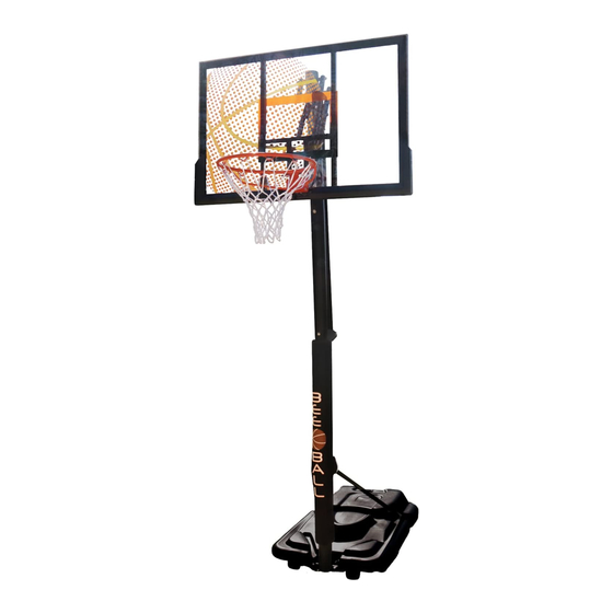
Instruction Manual for ZY-020 Ultimate Basketball
Notice to assemblers:
All the basketball systems, including those used for displays must be assembled and ballasted according
to instructions. Failure to follow instructions could result in serious injury. Please read all warnings and
cautions before assembly. It is recommended to supervise children as they play with this product. This
product is to be assembled by 2 adults only!
Stand
WARNING: IMPROPER
INSTALLATION OR SWINGING
ON THE RING MAY CAUSE
SERIOUS INJURY OR DEATH
Advertisement
Table of Contents

Related Manuals for Bee-Ball ZY-020

Summary of Contents for Bee-Ball ZY-020
- Page 1 Instruction Manual for ZY-020 Ultimate Basketball Stand WARNING: IMPROPER INSTALLATION OR SWINGING ON THE RING MAY CAUSE SERIOUS INJURY OR DEATH Notice to assemblers: All the basketball systems, including those used for displays must be assembled and ballasted according to instructions. Failure to follow instructions could result in serious injury. Please read all warnings and cautions before assembly.
- Page 2 Parts List:...
- Page 3 Parts List: Item # Quantity Description Base Backboard Basketball Rim Top Pole Middle Pole Bottom Pole Height Adjustment Upper Struts Height Adjustment Lower Struts Support Strut Left Support Strut Right Wheel Axle Base Cap Adjustment Bracket Wheels Adjustment Pole Top Cap Top Pole Cap Basketball Rim Fixing Bracket Basketball Rim Fixing Bracket Nuts...
- Page 4 Tip: To help you identify the bolts, this is how they are measured and listed. Tools Required: Spanner Set Socket set Please see advice below for correct nut and bolt assembly.
- Page 5 Assembly: Step 1. Align the pre drilled holes in the bottom of the top pole (DD) with the pre drilled holes in the top of the middle pole (EE). Secure using bolt F1,F2 and F3, completely tighten the nuts. Then align the pre drilled holes in the bottom of the middle pole (EE) with the pre drilled holes in the top of the bottom pole (FF).
- Page 6 Step 2. Now you have the upright pole built, you attach this to the base. We would recommend using some assistance in holding the pole upright while you fit the axel and wheels. To assemble the axle slide the wheel Axle (KK) through the base then through one wheel (part P) then through the bottom pole (FF) and then through the other wheel (part P).
- Page 7 Step 4. Assemble parts W1 and W2 together and put the U bolt (S) through the holes as shown below. (fig 4a and b). Secure them with bolts (H1) (fig. 4c). Loosely tighten the nuts as this stage. Step 5.
- Page 8 Attach the ring (CC) to the backboard (BB) and the brace (W1/W2) using the U bolt (S) through the two top holes. (Fig. 5a). Attach Parts U and T on the ends of the U bolt (S) then secure them all together with nuts (S1).
- Page 9 Attach the top of the braces (W1/W2) to the backboard using screws L1. You will need to apply some pressure on the bracket to get it to line up. Attach parts GG to the braces (W1/W2) using a bolt C1 at the top of the braces.
- Page 10 Step 7. For this stage it is best to lay the base and poles on the ground then attach part GG to the top pole (DD) of the basketball stand that you assembled earlier, use the top holes with bolt (A1). Attach part HH to the top pole (DD) in the next holes with bolt (A1).
- Page 11 Step 8. Slot part Q into part M. Part Q is the adjustment arm, once fitted your basketball stand will now be starting to take shape and get bigger so It is recommended that you have someone securing the unit while you are still assembling it.
- Page 12 Step 10. Place pole M between parts HH and fix together using bolt (B1) as shown below, please place spaces as shown below. Tighten the nuts however do not over tighten that they cannot move as they are part of the adjustment system and will need to freely move.
- Page 13 Step 12. Place the cap (R) onto the top of pole DD. Secure bolt D1 through the bottom hole on part GG above the top pole. At this stage you can remove the plastic film from the backboard.
- Page 14 Step 13. Attach the springs to the braces (W1/W2) as shown below using the pre drilled holes. Using the closed end of a spanner, pull the springs up and over the bolt D1. Then stand the unit up, recommended two people to lift it upright.
- Page 15 Step 14. Attach the net (X) to the ring as shown below. Step 15. Fill the base with 170kgs of sand. Put the tank cap in place. For safety reasons we would recommend filling the base with sand as opposed to water. Water is not recommended as if a small leak develops in the base, the water may escape and the stand would become unsecured , allowing the sand to fall over causing personal injury and/or death or property damage.
- Page 16 Height Adjustment This system may be adjusted from 7.5 feet till 10 feet in 6-inch increments. Hold the handle tight and squeeze the trigger. Raise or lower the handle to raise or lower the Backboard. WARNING: When adjusting the height, keep hands and fingers away from moving parts! Do not allow children to adjust the system.
- Page 17 Do not leave the system unsupervised or play on the system when the wheels are engaged for • moving Check the system before each use for instability • Do not use the system during windy and/or severe weather conditions; the system may tip over. •...
- Page 18 Big Game Hunters, Holly House, Pinewoods Road, Longworth, Oxon, OX13 5HG Tel: 01865 392439 sales@biggamehunters.co.uk www.biggamehunters.co.uk @thePlayExperts We like to ensure our products are quick and easy to assemble so you can start enjoying your purchase as soon as possible. If you have any recommendations on how the assembly instructions could be improved, please let us know.
Need help?
Do you have a question about the ZY-020 and is the answer not in the manual?
Questions and answers