Table of Contents
Advertisement
Advertisement
Table of Contents

Related Manuals for Masibus 1008S


Summary of Contents for Masibus 1008S
- Page 1 User’s Manual FLOW INDICATOR TOTALISER 1008S Masibus Automation & Instrumentation Pvt. Ltd. B/30, GIDC Electronics Estate, Sector-25, Gandhinagar-382044, Gujarat, India +91 79 23287275-79 +91 79 23287281-82 Email: support@masibus.com Web: www.masibus.com...
-
Page 2: Table Of Contents
4.1 Front Panel Description ................... 10 4.2 Rear Panel Diagram ..................10 4.2.1 Rear Panel Diagram Of 1008S Standard ............ 10 4.2.2 Rear Panel Diagram Of 1008S With Mass Flow ........11 5. MECHANICAL GUIDELINES ................ 12 5.1 Mounting Details ..................... 12 5.2 Mounting Steps .................... - Page 3 Issue No: 17 8.5 Parameter Flow ....................27 8.5.1 Parameter Flow Of 1008S Standard ............27 8.5.2 Parameter Flow Of 1008S With Mass Flow ..........29 9. CALIBRATION PROCEDURE................ 31 9.1 Input Calibration ....................31 9.2 Output Calibration ................... 31 9.2.1 Out zero and Out span .................
-
Page 4: Introduction
INTRODUCTION Forew ord Thank you for purchasing FLOW INDICATOR TOTALISER 1008S. This manual describes the basic functions and operation methods of 1008S. Please read through this user‟s manual carefully before using the product. Overview This is a microcontroller based Indicator - Totaliser unit, with very high performance to price ratio. - Page 5 Product Ordering Code: The FLOW INDICATOR TOTALISER 1008S unit has a nameplate affixed to the one side of the enclosure. Check the model and suffix codes inscribed on the nameplate to confirm that the product received is that which was ordered.
-
Page 6: Safety And Warning Precautions
Component replacement and interval adjustments must be done by a Masibus authorized or trained person only. Warning Precautions It is recommended that power of these units to be protected by fuses, circuit breakers or external over current rated at the minimum value possible. - Page 7 Flow Indicator Totaliser 1008S REF NO: m18A/om/101 Issue No: 17 CAUTION: High voltage transients may occur when switching inductive loads such as some contactors or solenoid valves. Through the internal contacts, these transients may introduce disturbances which could affect the performance of the instrument.
-
Page 8: Specifications
Flow Indicator Totaliser 1008S REF NO: m18A/om/101 Issue No: 17 3. SPECIFICATIONS 3.1 Measured input signal NUMBER OF INPUTS 1(one) with Optional 2 & 3 INPUT TYPE DC Input Current Input *Pulse Integrated/ 0-20 4-20 Input Batch Total 0-5 V... -
Page 9: Contact Output
Flow Indicator Totaliser 1008S REF NO: m18A/om/101 Issue No: 17 INPUT TYPE Non- voltage contact input or transistor open collector input 12VDC,10mA or more (for non – voltage contact input) INPUT CONTACT CAPACITY ON/ OFF DETERMINATION For non-voltage contact input ON = contact resistance of 1KΩ... -
Page 10: Environmental Specification
Flow Indicator Totaliser 1008S REF NO: m18A/om/101 Issue No: 17 TERMINAL (DIGITAL INPUT) circuit. RS-485 COMMUNICATION Isolated from other input/output terminals and internal circuit. TERMINAL POWER SUPPLY Isolated from other input / output terminals and internal TERMINAL circuit. GROUND TERMINAL Isolated from other input/ output terminals and internal circuit. -
Page 11: Front And Rear Panel Description
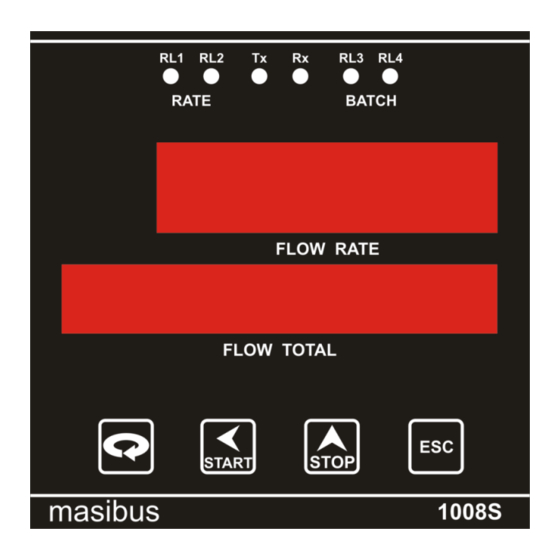
Flow Indicator Totaliser 1008S REF NO: m18A/om/101 Issue No: 17 FRONT AND REAR PANEL DESCRIPTION 4.1 Front Panel Description 4.2 Rear Panel Diagram 4.2.1 Rear Panel Diagram Of 1008S Standard User Manual... -
Page 12: Rear Panel Diagram Of 1008S With Mass Flow
Flow Indicator Totaliser 1008S REF NO: m18A/om/101 Issue No: 17 4.2.2 Rear Panel Diagram Of 1008S With Mass Flow User Manual... -
Page 13: Mechanical Guidelines
Flow Indicator Totaliser 1008S REF NO: m18A/om/101 Issue No: 17 MECHANICAL GUIDELINES 5.1 Mounting Details Structure: Front fascia IP54 complied(not certified), Enclosure GP (IP20) Body construction: Polycarbonate plastic. Case color: Dark grey Weight: 0.45Kg Instrument Dimension: 96 W* 96H*125D max behind panel with terminal (all in mm) ... -
Page 14: Terminal Connection Details
I/P+ POUT +Ve NC 3 +24V DC (50mA) Pulse o/p POUT -Ve COM 4 NO 4 Relay NC 4 6.2 Terminal Connection Detail Of 1008S With Mass Flow Line COM 1 RxTx+ RS 485 MAINS Serial Neutral 85-265 NO 1... -
Page 15: Wiring Diagram
Flow Indicator Totaliser 1008S REF NO: m18A/om/101 Issue No: 17 WIRING DIAGRAM 7.1 Wiring Diagram Of 1008S Standard User Manual... -
Page 16: Wiring Diagram Of 1008S With Mass Flow
Flow Indicator Totaliser 1008S REF NO: m18A/om/101 Issue No: 17 7.2 Wiring Diagram Of 1008S With Mass Flow User Manual... -
Page 17: Operating Details
Flow Indicator Totaliser 1008S REF NO: m18A/om/101 Issue No: 17 OPERATING DETAILS The following paragraphs give detailed description of how to operate the unit. Before using the instrument, make sure to study and understand this section. 8.1 Display Section: The unit has two windows/groups of display: ... -
Page 18: Run Mode Parameters Details
Flow Indicator Totaliser 1008S REF NO: m18A/om/101 Issue No: 17 8.3.1 Run Mode Parameters Details Name Description Max digits Limits Batch This parameter displays Max. 8 0 - 99999999 Total the Total flow since batch is started („BT‟) Integrated This parameter displays Max. -
Page 19: Edit Mode
Flow Indicator Totaliser 1008S REF NO: m18A/om/101 Issue No: 17 Start & Stop function:(In Run Mode) START key: If this key pressed batching relays (WP/EP) gets ON & BATCH TOTAL = 0.It means a new batch is started. If START key is pressed again and again, it will not start the batch until WP/EP relays gets OFF. -
Page 20: Program Mode
Flow Indicator Totaliser 1008S REF NO: m18A/om/101 Issue No: 17 8.4.1 Program mode Programming menu provides facility to configure the relay for different function. 8.4.1.1 Program Mode parameters Details Name Description No of Hi limit digit limit High Alarm Alarm... -
Page 21: Configuration Mode
Issue No: 17 8.4.2 Configuration mode Configuration mode provides facility to configure type of mode, type of input, baud rate for communication, etc. Every parameter are explained in the next section. 8.4.2.1 Configuration Mode Parameters Of 1008S Standard Name Description No Of... - Page 22 Low, High Selection frequency type low. Pulse width To set width of input pulse in low 0 To 50 frequency mode. 8.4.2.2 Configuration Mode Parameters Of 1008S With Mass Flow Name Description No Of Lo Limit Hi Limit Digit Batch Mode...
- Page 23 Flow Indicator Totaliser 1008S REF NO: m18A/om/101 Issue No: 17 Rounding 1,2,5,10 Over Range If Yes then integration total will be Yes/No running according to process value corresponding to 20ma and if No then integration total will stop after over limit is reached.
- Page 24 Flow Indicator Totaliser 1008S REF NO: m18A/om/101 Issue No: 17 Batch counter and no of batches: These parameters will be displayed only if the ‟Batch mode‟ is selected to Counter type. No of batches: Set the parameter according to the requirement. It decides how much batches are to be taken ...
- Page 25 Flow Indicator Totaliser 1008S REF NO: m18A/om/101 Issue No: 17 Input Flow Param Display Value Current rate eter Value 2000 4000 12.0 4500 13.6 7500 16.8 In above example Flow rate on 100% 10000 Display varies between: 0 – 2000 for input of 0 % – 10% ...
- Page 26 Flow Indicator Totaliser 1008S REF NO: m18A/om/101 Issue No: 17 Password: A „PASS‟ parameter is added in configuration mode. But it will always show „0000‟.User has to remember the password .If user needs to change password, then go in „pass‟ parameter, enter the required password and press Enter key.
-
Page 27: Calibration Mode
Flow Indicator Totaliser 1008S REF NO: m18A/om/101 Issue No: 17 Over Range: If this parameter is yes then integration total will be adding according to process value corresponding to 20ma and if this parameter is no then integration total will stop adding after over limit is reached. -
Page 28: Parameter Flow
(Pulse input 0 to 10KHz, 4-20mA, 1-5V) 2). When input is out of the range the display will blink. 8.5 Parameter Flow 8.5.1 Parameter Flow Of 1008S Standard How to operate menu is shown below in the form of flow diagram User Manual... - Page 29 Flow Indicator Totaliser 1008S REF NO: m18A/om/101 Issue No: 17 User Manual...
-
Page 30: Parameter Flow Of 1008S With Mass Flow
Flow Indicator Totaliser 1008S REF NO: m18A/om/101 Issue No: 17 8.5.2 Parameter Flow Of 1008S With Mass Flow How to operate menu is shown below in the form of flow diagram User Manual... - Page 31 Flow Indicator Totaliser 1008S REF NO: m18A/om/101 Issue No: 17 User Manual...
-
Page 32: Calibration Procedure
Flow Indicator Totaliser 1008S REF NO: m18A/om/101 Issue No: 17 CALIBRATION PROCEDURE 9.1 Input Calibration As explained earlier, One can do calibration thro' the keyboard itself, Zero and Full-scale values are stored in NVRAM. 1. Switch on the instrument and allow 15 minutes of warm up time before starting calibration. -
Page 33: Communication Guidelines
Cmd Action = 5 Reg Address = 0x0005 For Start – write 1 For Stop – write 0 10.3 Modbus RTU protocol addresses for RS 485 Communication 10.3.1 Addresses Of 1008S Standard Sr. No. Reg. No. Parameter Name Length in... - Page 34 Flow Indicator Totaliser 1008S REF NO: m18A/om/101 Issue No: 17 40010 Type of input 2(1) R/W (0 for 0-5V, 1 for 1-5V, 2 for 0-20mA, 3 for 4-20mA, 4 for pulse) 40011 Type of Inst 2(1) R/W (0 for indicator, 1 for Totaliser)
-
Page 35: Addresses Of 1008S With Mass Flow
0 for 10, 5 for 60, 1 for 20, 6 for 70, 2 for 30, 7 for 80, 3 for 40, 8 for 90, 4 for 50, 9 for 100 10.3.2 Addresses Of 1008S With Mass Flow Sr. No. Reg. No. Parameter Name Length in... - Page 36 Flow Indicator Totaliser 1008S REF NO: m18A/om/101 Issue No: 17 40019 2(1) 40020 FS + 2 2(1) 40021 2(1) 40022 No of batches 2(1) R/W (0 to 99) 40023 Batch counter 2(1) Read only 40024 Relay mode 2(1) R/W (0 for normal, 1 for failsafe)
- Page 37 Flow Indicator Totaliser 1008S REF NO: m18A/om/101 Issue No: 17 Low alarm Relay R, digital (1 for ON, 0 for OFF) Status High alarm Relay R, digital (1 for ON, 0 for OFF) Status Pre warm Point R, digital (1 for ON, 0 for OFF)
-
Page 38: Miscellaneous
Flow Indicator Totaliser 1008S REF NO: m18A/om/101 Issue No: 17 11. MISCELLANEOUS RETRAMISSION OUTPUT TABLE FOR OPEN /OVER /UNDER CONDITION: For 4-20mA:- DISPLAY RX O/P (mA) INPUT FEED (mA) SQUARE SQUARE LINEAR ROOT LINEAR ROOT I/P <1.60 OPEN OPEN 4.00... -
Page 39: Troubleshooting
Flow Indicator Totaliser 1008S REF NO: m18A/om/101 Issue No: 17 TROUBLESHOOTING If the operating display does not appear after turning on the controller‟s power, follow the measures in the procedure below. If a problem appears complicated, contact our sales representative.
Need help?
Do you have a question about the 1008S and is the answer not in the manual?
Questions and answers