Table of Contents
Advertisement
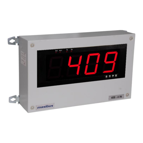
Temperature Indicator : 409-4IN
REF NO: m47/om/201
Issue NO: 04
User's Manual
409-4IN Temperature Indicator
Masibus Automation and Instrumentation Pvt. Ltd.
B/30, GIDC Electronics Estate,
Sector-25, Gandhinagar-382044, Gujarat, India
Phone : +91-79-23287275/79.
Fax : +91-79-23287281.
Email: support@masibus.com
Web: www.masibus.com
Page 1 of 34
Advertisement
Table of Contents

Related Manuals for Masibus 409-4IN


Summary of Contents for Masibus 409-4IN
- Page 1 Temperature Indicator : 409-4IN REF NO: m47/om/201 Issue NO: 04 User’s Manual 409-4IN Temperature Indicator Masibus Automation and Instrumentation Pvt. Ltd. B/30, GIDC Electronics Estate, Sector-25, Gandhinagar-382044, Gujarat, India Phone : +91-79-23287275/79. Fax : +91-79-23287281. Email: support@masibus.com Web: www.masibus.com Page 1 of 34...
-
Page 2: Table Of Contents
Temperature Indicator: 409-4IN REF NO: m47/om/201 Issue NO: 04 Contents Introduction ......................... 4 Product Overview/Description ............................4 Model and Suffix code ..............................4 Accessory ..................................5 Safety/Warning Precaution ..................5 Front Panel Description ....................5 Keyboard and Operation ..............................5 Terminal Arrangement Diagram ................. - Page 3 Temperature Indicator : 409-4IN REF NO: m47/om/201 Issue NO: 04 Alarm:.................................... 29 Transmission output ..............................30 Supply voltage: ................................30 Power Consumption: ..............................30 Insulation resistance: ..............................30 Environment: ................................. 30 Case: 30 Mounting method: ................................ 31 Dimension: ..................................31 Panel Cutout: .................................
-
Page 4: Introduction
Model-409-4IN accepts 21 different types of inputs (all industry standard input) which are field configurable, facilitates plant operator to use in any application. 409-4IN is easy to operate and configuration is user friendly. -
Page 5: Accessory
Temperature Indicator : 409-4IN REF NO: m47/om/201 Issue NO: 04 Accessory The product is provided with the following accessory. (See the table2below). Item name Part number Remarks Mounting Clamps Table 2. Safety/Warning Precaution The product and the instruction manual describe important information to prevent possible harm to users and damage to the property and to use the product safely. - Page 6 Temperature Indicator: 409-4IN REF NO: m47/om/201 Issue NO: 04 Fig 2. Front Panel for Panel Mount Name of Part Symbol Function Increment the Value of any Parameter UP key User presses during RUN mode to invoke segment testing mode*.
-
Page 7: Terminal Arrangement Diagram
Temperature Indicator : 409-4IN REF NO: m47/om/201 Issue NO: 04 Terminal Arrangement Diagram Fig 3. Terminal Arrangement for Panel Mount Fig 4. Terminal Arrangement for Wall mount 4.1 Terminal Description Terminal Description SYMBOL Mains Supply 90-270VAC NC1 Normally close-1 Relay 1... - Page 8 Temperature Indicator: 409-4IN REF NO: m47/om/201 Issue NO: 04 RTD common For RTD Input Only (Three wire Compensation). Rs-485 Communication (Serial Input) Retransmission Output Table 3. Page 8 of 34...
-
Page 9: Menu Layout
Temperature Indicator : 409-4IN REF NO: m47/om/201 Issue NO: 04 Menu Layout Menu Layout Page 9 of 34... -
Page 10: Run Time Indication/Function
Temperature Indicator: 409-4IN REF NO: m47/om/201 Issue NO: 04 RUN Time Indication/Function Following parameters can view or change during run time. For Thermocouple input type, Press Decrement key to show ambient temperature. For Alarm Acknowledgment, Press Enter Key. - Page 11 Temperature Indicator : 409-4IN REF NO: m47/om/201 Issue NO: 04 0-2V .4-2V -10-20 mV 1-75 mV 0-75 mV SERL 4-20 mA* 0-20 mA* Use external 250ohms,0.1% for current input Set position of Decimal Point on Display. 1 /0.1 /0.01 /0.001...
- Page 12 Temperature Indicator: 409-4IN REF NO: m47/om/201 Issue NO: 04 Alrm /Trip 0 : ALRM 1 : TRIP Set which Set Point to shown in SV display in RUN mode while device is in Auto Mode ATYP HH/HL/LL Alarm Type (ATYP)
-
Page 13: Calibration Mode
Temperature Indicator : 409-4IN REF NO: m47/om/201 Issue NO: 04 Adjust Brightness of the 7-segment Display. BRHT Brightness (brHt) 10 to 100 Set Device Password PASS Password (pass) 0 to 99 VERS Version Shows the Version of the Current Firmware... - Page 14 Temperature Indicator: 409-4IN REF NO: m47/om/201 Issue NO: 04 Example: 1. How to change Input Type 2. How to change Control Set Point-1 Page 14 of 34...
-
Page 15: Control Function
Temperature Indicator : 409-4IN REF NO: m47/om/201 Issue NO: 04 CONTROL FUNCTION ON/OFF Control ON/OFF Controller is the simplest form of temperature control device. The output from the device is either on or off, with no middle state. An on-off controller will switch the output only when the temperature crosses the set point. -
Page 16: 6.2 Messages During Open Sensor Condition
Temperature Indicator: 409-4IN REF NO: m47/om/201 Issue NO: 04 6.2 Messages during OPEN SENSOR condition Input type Message TC-E OPEN TC-J OPEN TC-K OPEN TC-T OPEN TC-B OPEN TC-R OPEN TC-S OPEN PT 100 OPEN 0-400Ω OPEN 0-6000Ω OPEN ±10V... -
Page 17: Retransmission Output During Open Sensor/Diode Open Condition
Temperature Indicator : 409-4IN REF NO: m47/om/201 Issue NO: 04 Process value greater then maximum value of zero/span then display will show OPEN message. Retransmission o/p will follow 5% of display range and then it will give fixed o/p depending up on OPEN sensor selection. In case of linear inputs scaling is applied then during OPEN sensor condition it may not show OPEN message instead it will show either OVER/UNDER. -
Page 18: 6.3 Relay Delay
Temperature Indicator: 409-4IN REF NO: m47/om/201 Issue NO: 04 0-10 V O/P 0-5 V O/P 1-5 V O/P UP Scale O/P DW Scale O/P UP Scale O/P DW Scale O/P UP Scale O/P DW Scale O/P 10.50 5.25 5.20 0.80 Pt-100 10.50... -
Page 19: 6.4 Control Relay
Temperature Indicator : 409-4IN REF NO: m47/om/201 Issue NO: 04 6.4 Control Relay Control relay “OFF” then relay will function according to the condition mention in the following tables. Control relay “ON” then functioning of relay will be just opposite to the condition mention in the table. - Page 20 Temperature Indicator: 409-4IN REF NO: m47/om/201 Issue NO: 04 Alarm AL2 (Momentary Alarm): when in abnormal condition ACK not pressed. Condition Normal Abnormal DOWN ACK** Normal* ACK*** Alarm LAMP FLASH FLASH FLASH Latch(Yes) RELAY Alarm LAMP FLASH FLASH VHigh Latch(No)
- Page 21 Temperature Indicator : 409-4IN REF NO: m47/om/201 Issue NO: 04 LAMP FLASH STEADY STEADY Trip RELAY Alarm LAMP FLASH FLASH STEADY STEADY Latch(Yes) RELAY Alarm LAMP FLASH FLASH STEADY Latch(No) RELAY LAMP FLASH STEADY STEADY Trip RELAY Alarm LAMP FLASH...
- Page 22 Temperature Indicator: 409-4IN REF NO: m47/om/201 Issue NO: 04 Alarm AL2 (Maintained Alarm): when in abnormal condition ACK is pressed. Condition Normal Abnormal DOWN ACK** Normal* ACK*** LAMP FLASH FLASH STEADY STEADY Alarm Latch(Yes) RELAY Alarm LAMP FLASH FLASH STEADY...
-
Page 23: Calibration Procedure
Temperature Indicator : 409-4IN REF NO: m47/om/201 Issue NO: 04 Calibration Procedure Calibration for Input The calibration in the instrument is using front panel keys only. Instrument can be calibrated even during installed condition. Calibration is carried out using following steps. -
Page 24: Calibration For Retransmission
Temperature Indicator: 409-4IN REF NO: m47/om/201 Issue NO: 04 Calibration for Retransmission The calibration in the instrument is using front panel keys only. Instrument can be calibrated even during installed condition. Calibration is carried out using following steps. 1) Enter in to calibration mode using front panel keys. Display indicates “CAl” in 4- segment display. -
Page 25: Communication Parameter
Temperature Indicator : 409-4IN REF NO: m47/om/201 Issue NO: 04 Communication Parameter Introduction The unit can be connected in RS-485 communication data link either in multi drop or repeat mode. Each unit must have unique Serial Number. Entire range of addresses (1 to 247) may be used. - Page 26 Temperature Indicator: 409-4IN REF NO: m47/om/201 Issue NO: 04 Span display 40002 Integer Set point 1 40003 Integer Set point 2 40004 Integer Relay delay 40005 Unsigned Integer 9999 Brightness 40006 Unsigned char *Input type selected 40007 Unsigned Integer *Decimal point...
-
Page 27: Parameter Address Details For Mtyp : B (405-4In)
Temperature Indicator : 409-4IN REF NO: m47/om/201 Issue NO: 04 *Alarm status1, *Alarm status2 gives status of abnormal condition only. Address 1006- 1016 for future use only *Input type: 0 = Etc, 1 = Jtc, 2 = Ktc, 3 = Ttc,4 =Btc,5 =Rtc, 6 = Stc, 7= pt-100,8 = 0- 400Ω, 9 =0-6000Ω, 10 = ±10V, 11 = 0-10V, 12 = 0-5V, 13 = 1-5V,14 = 0-2V,15 = 0.4-... -
Page 28: Exceptional Response
Temperature Indicator: 409-4IN REF NO: m47/om/201 Issue NO: 04 Exceptional Response CODE MEANING Function code Invalid. It must be 01, 03, 04,05 or 16.The function code received in the query is not allowable action for the slave. Illegal address value. The data address received in the query is not an allowable address for the salve. -
Page 29: Input Sampling Period
Temperature Indicator : 409-4IN REF NO: m47/om/201 Issue NO: 04 0.4 – 2V Voltage -1999 to 9999 ± 10V -1999 to 9999 0-10 V -10-20mV ± 75 mV 0-75 mV 0-400Ω Resistance Input 0-6000Ω Serial PV Write Facility -1999 to 9999 * For DC Current input, 250Ω... -
Page 30: Transmission Output
Temperature Indicator: 409-4IN REF NO: m47/om/201 Issue NO: 04 Alarm AL2 - Momentary Alarm Condition – vhigh/high/low Lamp – on/flash/latch Relay – on/off Transmission output DC Current: 0 to 20 mA DC, 4 to 20 mA DC DC Voltage: 0 to 10V DC, 0 to 5V DC, 1 to 5V DC. (One at a time factory settable). -
Page 31: Mounting Method
Temperature Indicator : 409-4IN REF NO: m47/om/201 Issue NO: 04 Mounting method: Panel / Wall / 19” Rack Mounting Dimension: IP 20 : 440mm (W) x 175mm (H) x 70mm (D) IP 65 : 500mm (W) x 300mm (H) x 120mm (D) Panel Cutout: 444mm(+0.8) x 175mm(+0.8) -
Page 32: Special Feature
Temperature Indicator: 409-4IN REF NO: m47/om/201 Issue NO: 04 At least 1500 V AC for 1 minute Between secondary terminals**: At least 500 V AC for 1 minute * Primary terminals indicate power terminals and relay output terminals. ** Secondary terminals indicate analog I/O signal and Communication O/P. -
Page 33: Appendix
Temperature Indicator : 409-4IN REF NO: m47/om/201 Issue NO: 04 Appendix Troubleshooting Jumper Location for Retransmission Output Jumper Setting for Retransmission card: m61Cao102 Page 33 of 34... -
Page 34: Square Root Linearization
Temperature Indicator: 409-4IN REF NO: m47/om/201 Issue NO: 04 Square Root Linearization The formula for square root is: Vinput Vlow Vhigh Vlow PV = Zero + [(Span - Zero) Where: Span is the high end of process variable...
Need help?
Do you have a question about the 409-4IN and is the answer not in the manual?
Questions and answers