Antec LanBoy Air User Manual
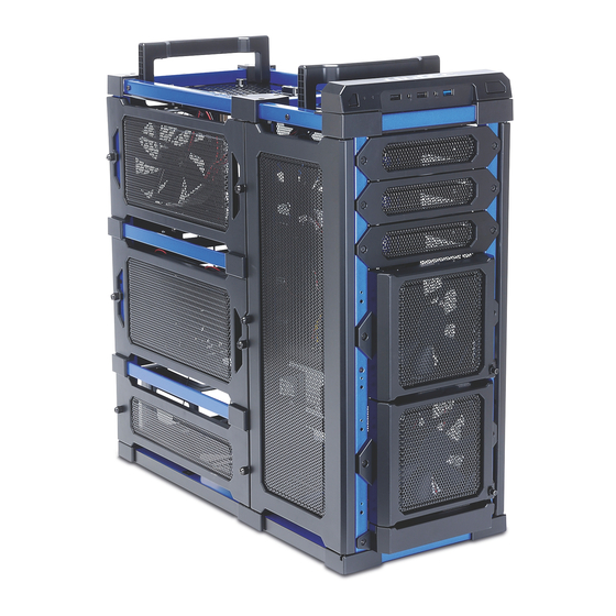
The most modular, most customizable open-air chassis
Hide thumbs
Also See for LanBoy Air:
- User manual (5 pages) ,
- User manual (3 pages) ,
- User manual (28 pages)

Related Manuals for Antec LanBoy Air


Summary of Contents for Antec LanBoy Air
- Page 1 All manuals and user guides at all-guides.com ODULAR USTOMIZABLE HASSIS S E R A N U A L...
- Page 2 Congratulations on your purchase of the Antec LanBoy Air. The LanBoy Air is the most modular, most customizable open-air chassis. Nearly every part on this chassis, down to the motherboard and PSU mounts, is removable and customizable. The LanBoy Air’s cooling system allows up to 15 inward-facing fans to create positive internal air pressure, blowing dust and heat out through its panel perforations.
-
Page 3: Table Of Contents
All manuals and user guides at all-guides.com ABLE OF ONTENTS 1: I ECTION NTRODUCTION Getting to Know your Chassis .................. 5 Chassis Specifications ....................6 Included Screws ......................6 Before you Begin ......................7 2: H ECTION ARDWARE INSTALLATION Setting up ........................9 Internal 3.5”... -
Page 4: Section 1 Introduction
All manuals and user guides at all-guides.com ECTION NTRODUCTION... -
Page 5: Getting To Know Your Chassis
All manuals and user guides at all-guides.com ETTING TO KNOW YOUR CHASSIS Drive Bays Hardware Mounts 1 5.25" drive bays default location 10 Removable motherboard tray 2 3.5" AirMount™ drive bays default location 11 Removable power supply mount 3 2.5" internal SSD bay 12 Front I/O ports 4 Built-in toolbox for spare screws/parts 13 8 expansion slots... -
Page 6: Included Screws
NCLUDED CREWS The LanBoy Air is designed to be extremely flexible. A variety of screws are included to accommodate the multitude of configurations that are possible with this chassis. The included toolbox depicted in section 1.1 contains most of these screws. -
Page 7: Before You Begin
EFORE EGIN In order to ensure that your building experience with the LanBoy Air will be a positive one, please take note of the following: While working inside your LanBoy Air, keep your chassis on a flat, stable surface. Make sure your build •... -
Page 8: Section 2 Hardware Installation
All manuals and user guides at all-guides.com ECTION ARDWARE NSTALLATION... -
Page 9: Setting Up
Note: The order in which hardware is installed in this manual is different from that of typical cases; this is due to the unique design of the LanBoy Air chassis. We recommend that you follow the order laid out in this manual, as it takes full advantage of the LanBoy Air’s features. - Page 10 The LanBoy Air utilizes Antec’s revolutionary AirMount™ suspension HDD mounting system. This system suspends hard drives in the drive bays, reducing vibration and subsequent noise. To mount drives using AirMount™: 1.
-
Page 11: External 5.25" Device Installation
All manuals and user guides at all-guides.com Note: If you are transporting the LanBoy Air, it is recommended that you remove any hard drives prior to transport. 5.25” D XTERNAL EVICE NSTALLATION There are three externally accessible 5.25” drive bays. Drives can be mounted in three possible horizontal orientations. -
Page 12: Removing And Relocating The Motherboard/Psu
1. Insert the rubber grommets into the mounting holes, with the larger portion of the grommet facing the top of the case (Figure 12). 2. Lay the LanBoy Air on its side, so you can access the outside bottom of the chassis. - Page 13 All manuals and user guides at all-guides.com 4. Remove the four screws holding the PSU mount in place. Lift and remove the mount, moving it towards the front of the chassis (Figure 18).
- Page 14 All manuals and user guides at all-guides.com Figure 18 – PSU mount screw locations 5. Working with the right side of the chassis, remove the two screws securing each of the rails that the motherboard slides on. Remove the rails by pulling on the side facing the front of the chassis first. (Figure 19). Figure 19 –...
-
Page 15: Motherboard Installation
All manuals and user guides at all-guides.com Figure 21 – PSU mount screw locations 8. Once you have secured the rails and PSU mount, the chassis should now look similar to Figure 22. Figure 22 OTHERBOARD NSTALLATION Before proceeding: Check the manual for your CPU cooler to find out if there are steps you must do before installing the motherboard •... - Page 16 All manuals and user guides at all-guides.com Note: This section assumes that you have removed the motherboard tray in section 2.5. If you are installing a motherboard directly into the chassis, lay the chassis on its side with the drive mounts on the right.
-
Page 17: Power Supply Installation
The LanBoy Air provides mounting holes for power supplies with standard mounting layouts to be installed right side up or upside down. -
Page 18: Cable Management
All manuals and user guides at all-guides.com ABLE ANAGEMENT There is a cable management area between the motherboard tray and right side panel, as well as cable ties located on the back of the motherboard panel. You can tuck excess cables into this compartment. 1. -
Page 19: Section 3 Front I/Oports
All manuals and user guides at all-guides.com ECTION RONT ORTS... -
Page 20: Usb 2.0
All manuals and user guides at all-guides.com USB 2.0 Connect the front I/O panel USB cable to the USB header pin on your motherboard. Check your motherboard user’s manual to ensure that it matches the table below: Signal Names Signal Names USB Power 1 USB Power 2 Negative Signal 1... -
Page 21: Front Panel Ground Wire Installation
ROUND NSTALLATION The LanBoy Air includes a grounding wire for the front panel ports. This wire should be attached to the chassis using one of the PSU screws, as depicted in Figure 29. Figure 29 – Attaching the front panel ground wire... -
Page 22: Rewiring Motherboard Header Connections
All manuals and user guides at all-guides.com EWIRING OTHERBOARD EADER ONNECTIONS There may come a time when you need to reconfigure the pin-out of a motherboard header connector. Examples could be for your USB header, audio input header, or some other front panel connector such as the Power Button connector. Before performing any work, please refer to your motherboard user’s manual or your motherboard manufacturer's website to confirm the pin-out needed for your connector. -
Page 23: Section 4 Cooling System
All manuals and user guides at all-guides.com ECTION OOLING YSTEM... -
Page 24: Included Fans
™ LED F The LanBoy Air comes with one rear and two side 120 mm TwoCool™ LED fans. These fans have a two-speed switch that lets you choose the speed best suited to your need. The rear fan switch is located on the rear panel and the side fan switches are attached to the fans. -
Page 25: Front 120 Mm Led Fans With Variable Speed Control
ONTROL The LanBoy Air comes with two 120 x 25mm LED fans which are preinstalled in front the chassis to cool the hard drives. Each fan comes with a speed control knob at the front of the faceplate. Turn the knob clockwise to increase the speed. -
Page 26: Optional Fans
All manuals and user guides at all-guides.com PTIONAL The LanBoy Air can accommodate up to ten additional 120 mm fans in four different locations: 1. Two additional fans can be mounted inside the left larger panel. 2. Three fans can be mounted inside the left smaller panel 3. - Page 27 US & Canada 1-800-22ANTEC customersupport@antec.com Europe +31 (0) 10 462-2060 europe.techsupport@antec.com www.antec.com © Copyright 2010 Antec, Inc. All rights reserved. All trademarks are the property of their respective owners. Reproduction in whole or in part without written permission is prohibited.
Need help?
Do you have a question about the LanBoy Air and is the answer not in the manual?
Questions and answers