Table of Contents
Advertisement
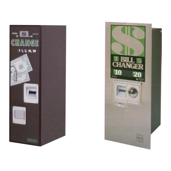
Bc-1200/1400
BC-1200/1400
Bill & Coin Changer
Bill & Coin Changer
with Fast Pay System
with Fast Pay System
Field Service Manual
and
Parts Catalog
PART NO. 25238802
REV. L
Advertisement
Table of Contents
Troubleshooting

Related Manuals for Rowe BC-1400


Summary of Contents for Rowe BC-1400
- Page 1 BC-1200/1400 BC-1200/1400 Bill & Coin Changer Bill & Coin Changer with Fast Pay System with Fast Pay System Field Service Manual Parts Catalog PART NO. 25238802 REV. L...
- Page 2 BC-1200/1400 Bill and Coin Changer Field Service Manual Parts Catalog Rowe by American Changer 1400 N.W. 65th Place Fort Lauderdale, Florida 33309 techsupport@rowebillchangers.com...
- Page 3 Machine Safety Your safety and the safety of others are very important to American Changer. We have provided important safety messages in this manual and on your machine. Always read and obey all safety messages. This is a safety alert symbol. This symbol alerts you to potential hazards that can kill or hurt you and others.
- Page 4 Important Safety Instructions DANGER: To reduce the risks of severe injury WARNING: To reduce the risk of electrical shock, secure the machine to a stable structure. disconnect all electrical power to the machine before servicing. NOTICE: For indoor use only. NOTICE: Ensure this machine is level when installed SAVE THESE INSTRUCTIONS...
- Page 5 Section 2 – Setup & Installation 2.2 – Mounting Instructions This machine must be installed in accordance with local codes. If you are unsure in any way what your local codes are or unsure of anything in the following steps, please hire a licensed professional to mount your machine.
- Page 6 PROPERLY SECURE MACHINE (PRODUCT) TO THE FLOOR SO THE MACHINE (PRODUCT) CANNOT BE MOVED OR TIPPED. USE STRUCTURAL SOUND FASTENERS THAT CAN BE PROPERLY TIGHTENED AND SECURE THE MACHINE (PRODUCT) THROUGH EACH OF THE HOLES IN THE BASE OF THE MACHINE (PRODUCT) TO THE APPLICABLE SURFACE TO WHICH IT IS BEING SECURED.
- Page 7 Preface This service manual is divided into six sections: Introduces you to the BC-1200 and BC-1400, their features, and their major Section 1 System Description — components, principles of operation, and capacities. Guides you through step-by-step installation instructions and Section 2 Installation and Programming —...
-
Page 8: Table Of Contents
Hoppers ................................1-6 Hopper Capacities ............................. 1-6 Machine Capacities (Bill Stacker, Coin Box) ......................1-7 Money Return Lever (BC-1200)/Money Return Switch (BC-1400) ................ 1-7 Temporarily Out of Service Lamp ........................1-8 EMI Filter ................................1-8 Power Control Center ............................1-8 Dollars Accepted Counter .......................... -
Page 9: Table Of Contents
Miscellaneous ..............................2-24 SECTION 3 — ROUTINE SERVICE Introduction ................................. 3-1 Removing the Bill Acceptor from a BC-1400 ....................3-1 Removing a Jammed Bill from the Bill Acceptor (BC-1200 Only) ..............3-3 Bill Jamming Check List ............................ 3-3 Filling and Emptying the BC-1200/1400 ......................3-4 Filling the Changer ............................ -
Page 10: Table Of Contents
Table of Contents SECTION 3 — ROUTINE SERVICE (Continued) Adjusting the Pusher Plate ..........................3-12 Adjusting the Bill Acceptor Rails ......................... 3-13 Adjusting the Bill Transport to Stacker Alignment ....................3-13 Adjusting the Upper Bill Box ..........................3-15 Bill Stop Flipper Check ............................3-16 Adjusting the Bill Stop Flipper .......................... -
Page 11: Table Of Contents
Table of Contents Stacker Solenoid ............................4-63 Coin Lockout ..............................4-63 Input Circuits ..............................4-64 Power Supply Circuit Board ..........................4-74 Computer Control Board ........................... 4-84 Bill Stacker Driver Circuit Board .......................... 4-93 Coin Switch Circuit Board ..........................4-95 SECTION 5 — ADDITIONAL INFORMATION Harness Color Coding ............................ - Page 12 Table of Contents Parts Catalog ..............................6-5 FREQUENTLY USED FIGURES AND TABLES Coin Acceptor Options (Table 1-1) ..........................1-4 Dispenser (Figure 1-5) ............................1-5 Computer Control Center (CCC) (Figure 1-9) ......................1-10 Diagrams Block Schematic Diagram (Figure 4-1) ....................... 4-68 Coin Switch Schematic (Figure 4-5) ..........................
- Page 13 Coin Hoppers - Holds nickels, dimes, Coin Acceptor quarters, dollar coins, (optional on the BC-1200, or tokens. not available on the BC-1400) - Accepts valid Hopper Bail Wire coins which operate solid- state switches to vend change. Coin Dispenser (behind hoppers) - Contains the drive 4. Load coin buckets with change by pressing...
-
Page 14: Introduction
1, 2, 5, 10, and 20 dollar bills of United States currency. The BC-1400 accepts 1, 2, 5, 10, and 20 dollar bills of United States currency. The coin acceptor option is not available on the BC-1400. -
Page 15: Changing Coins
BC-1200/1400 Bill and Coin Changer The one dollar change bucket opens, and the dollar’s worth of change drops into the coin cup. The coin hopper motors then operate, loading the correct number of coins from the left, and right coin hoppers into the change bucket for the next payout. -
Page 16: Dual Bill Stacker
Section 1: System Description Figure 1-3. Bill Transport (Bottom View) Dual Bill Stacker The dual bill stacker in Figure 1-4 has the capability of stacking bills in two separate bill boxes. This feature allows the bill changer to alternate between the two bill boxes or to separate bills by denomination. -
Page 17: Coin Acceptor
CCC that it is ready for the next cycle. Coin Acceptor (Optional on BC-1200; Not available on BC-1400) The coin acceptor checks the coins for which it was designed to determine their validity. Each coin is checked for thickness, diameter, weight, and metallic content. -
Page 18: Solid-State Coin Switches
Section 1: System Description Solid-State Coin Switches As a coin passes through a slot in the coin switch assembly with any mechanical coin acceptor, it momentarily interrupts an infrared light beam, causing a solid-state optical detector to send an electric pulse to the CCC. The duration of this pulse is then checked by the computer to determine its validity. -
Page 19: Hoppers
BC-1200/1400 Bill and Coin Changer Hoppers The bill changer contains two coin hoppers (see Figure 1-6) which mount on the front surface of the dispenser assembly and pivot forward from the bottom for loading, unloading, and removal (see Table 1-2 for required hopper types and capacities). -
Page 20: Machine Capacities (Bill Stacker, Coin Box)
Coin Box 500 Quarters NOTE: For escrow bucket capacities, see Table 2-1. Money Return Lever (BC-1200) / Money Return Switch (BC-1400) When the lever on the BC-1200 (see Figure 1-7) or the switch on the BC-1400 MONEY RETURN MONEY RETURN is depressed, a switch closes and sends a signal to the CCC. -
Page 21: Temporarily Out Of Service Lamp
BC-1200/1400 Bill and Coin Changer Temporarily Out of Service Lamp This lamp lights whenever the machine is empty of change or shutdown due to some malfunction. In addition, the 40 VDC LED will normally go out if the out of service lamp is lit. Press the button on the CCC to turn FUNCTION light off after the machine has been reloaded or if the malfunction has been repaired. -
Page 22: Dollars Accepted Counter
Section 1: System Description DOLLARS ACCEPTED COUNTER The dollars accepted counter registers the number of dollars accepted by the machine. The counter increments once for each dollar. (For example: A $5 bill will make the counter increment five times.) This counter is not resettable. POWER SUPPLY switch controls power to the machine. -
Page 23: Computer Control Center
BC-1200/1400 Bill and Coin Changer Computer Control Center The computer control center (referred to as the “CCC” and shown in Figure 1-9) directs all of the operations of the bill changer including both validation and change dispensing functions. It contains a microcomputer which controls all of the major functions of the bill changer. - Page 24 Section 1: System Description Value Button Pressing the VALUE button will cause the display to show the total dollar amount accepted since the temporary audit value was cleared. Thus, if you clear this audit counter (see Section 2) each time you load the hoppers, you can quickly see how much change has been paid out and thus determine whether or not the bill changer needs to be loaded again.
-
Page 25: Denominations Accepted
The BC-1200, if so configured, can accept quarters and dollar coins as well as 1, 2, 5, 10, and 20 dollar bills of United States currency. All of these denominations can be selected in combination with other denominations. BC-1400 The BC-1400 has all the functions and capability of the BC-1200 (in the previous paragraph), except that it does not accept coins. 1-12... -
Page 26: Installation
Always use a grounded (3-prong) outlet. NOTE: For both security and safety reasons, Rowe strongly recommends that this bill changer be securely anchored to the floor and/or wall. Please check the instructions that follow:... - Page 27 BC-1200/1400 Bill and Coin Changer Cabinet Back Cut here Note: Drill or use a chassis punch to enlarge the hole to 7/8" diameter in the cabinet back. Route the conduit through the Remove the hoppers and cover of the junction opening into the bracket as shown. box located on the right side of the changer. Then, cut the existing Power Cord as shown. Conduit Connect the power supply wires to the internal machine wires per the wiring diagram, using standard U.L. listed insulated pressure cable connectors (wire nuts etc.). Do not splice the earth ground wire. Fasten it to the bracket with the green screw and cup washer as shown. Figure 2-1. Installing a 1/2-Inch Conduit 2 - 2 25238802...
- Page 28 Section 2: Installation & Programming Lead Anchors Lag Screw NOTE: Be sure that the lag screws used for attachment are at least 3/8" diameter and, for wood frame walls, are attached directly to the wall studs. Mounting Detail - Wood Frame Wall Mounting Detail - Masonry Wall Concrete Changer Wall Stud Lead Anchor & Lag Screw Lag Screw & Washer Figure 2-2. Attaching the BC-1200 to a Wall 25238802 2 - 3...
-
Page 29: Installing A Bc-1400
For all methods of installation, locate a convenient power source, and be sure that the bill changer is mounted level. The BC-1400 is primarily designed to be flush mounted on a wall with the cabinet itself protruding through a hole (or cutout) in the wall. - Page 30 Section 2: Installation & Programming Cut off and strip the wires at this point and remove Cabinet Door the supply cord. Cut here Note: Drill or use a chassis punch to enlarge the hole to 7/8" diameter in the cabinet top and route the conduit through the opening into the bracket as shown. Connect the power supply wires to the internal machine wires per the wiring diagram. Use standard U.L. listed insulated pressure cable connectors, such as wire nuts. Conduit Do not splice the earth ground wire. Fasten it to the bracket with the green screw and cup washer as shown. Figure 2-4. Installing 1/2-Inch Coinduit (BC-1400) 25238802 2 - 5...
-
Page 31: Change Payout Programming
BC-1200/1400 Bill and Coin Changer CHANGE PAYOUT PROGRAMMING Many different change combinations can be dispensed for the various denominations of money accepted. Change payout programming is accomplished using the five buttons on the CCC. As mentioned earlier, there are mechanical limitations which must be considered. - Page 32 Section 2: Installation & Programming There are very few payout combinations which cannot be allowed. If you review them briefly, you will easily understand why they cannot be used. Table 2-2 lists those combinations: Table 2-2. Acceptance Combinations Which Are Not Allowed 50¢...
-
Page 33: Loading The Hoppers
BC-1200/1400 Bill and Coin Changer LOADING THE HOPPERS Review Figure 2-5 before you begin. 1. Pull the hopper forward to its stop point. 2. Twist the top of a full coin bag one full turn. Grasp the twisted top with one hand and hold the bottom of the bag with the other. -
Page 34: Operational Information
Located on the computer control board Switches Status Display Located on the computer control board MONEY RETURN Switch Located behind the MONEY RETURN lever on the front of the machine (BC-1200) Located behind the faceplate (BC-1400) 25238802 2 - 9... -
Page 35: Setting Up The Bc-1200 Or Bc-1400
BC-1200/1400 Bill and Coin Changer SETTING UP THE BC-1200 OR BC-1400 These steps should be followed to set up the changer to your requirements. If you do not follow these steps, the changer will remain all or partially programmed to the factory settings. -
Page 36: Normal Setup
BILL B CHECK ON button to select either . This is a security check made during the bill validation process. Rowe recommends the “ ” setting for all but the most extreme circumstances where a very high percentage of bills are rejected with Code “B”... -
Page 37: Switching To The Programming Mode
BC-1200/1400 Bill and Coin Changer Switching to the Programming Mode Steps 1 and 2 display “audit” information. To enter the mode: PROGRAMMING 1. Move the slide switch on the CCC to the mode position. PROGRAMMING The display will change from the “walking dash” to “ ”. -
Page 38: If An Access Code Has Been Established
Section 2: Installation & Programming IF AN ACCESS CODE HAS BEEN ESTABLISHED A. The left two digits of the access code will be blinking. (This is the BC-1200/1400’s way of indicating which information will be changed if you make a change.) Press the ^ or button to change the left two digits of the four-digit access code. - Page 39 BC-1200/1400 Bill and Coin Changer Operation in the mode can be described simply as follows: The computer will get the total required number of coins from any hopper or hoppers that it can. If both hoppers are operational, it will divide the required payout amount (say, 20 quarters for a $5 bill for example) by two and replenish ten coins from each hoppers for the count of 20.
- Page 40 Section 2: Installation & Programming Use the coin value stickers suppled in the accessories bag to label the hoppers as a reminder of which coins are to be loaded in each hopper. Table 2-3. Hopper Value Codes Display Symbol Money Type Nickel Dime Quarter...
- Page 41 BC-1200/1400 Bill and Coin Changer 11. After you have programmed the denominations you wish to accept, press the button to move on FUNCTION to the function. PAYOUT 12. The display will show: . The will be the lowest bill denomination set to XXX PAY - - - - - - The left digits will be blinking.
- Page 42 ) provides maximum security against bogus BILL B CHECK ON bills. This is the factory setting and Rowe strongly recommends its use for all but the most severe environments. position improves acceptance of bills which are contaminated with metal chips or BILL B CHECK OFF dust, but also reduces protection against bogus bills.
-
Page 43: Self-Diagnostics
BC-1200/1400 Bill and Coin Changer SELF-DIAGNOSTICS Diagnostic Check The self-diagnostic check features of the BC-1200/1400 are centered around the 16-character status display. The message displayed may be on all the time ( ), or it may blink on and off ( STEADY STATUS MESSAGE FLASHING FAULT MESSAGE... -
Page 44: Acceptance Check
Section 2: Installation & Programming 2. Hold the bill in the transport. Do not uncover the VI cell. Wait five seconds for the transport to start to cycle reverse-forward-reverse-forward-reverse. The transport will do this three times if the VI cell is kept covered. -
Page 45: Dispensing Tokens
BC-1200/1400 Bill and Coin Changer DISPENSING TOKENS A unique situation exists when dispensing tokens while in the mode. The ability to payout a progressive bonus is allowed, even if payout is normally an extended vend of a lower denomination. Normally, in the mode or when paying out coins, some denominations require an extended dispense–direct NON-MC payout–replenish cycle. -
Page 46: Token Control
Section 2: Installation & Programming Token Control When dispensing tokens using the bonus payout, it is difficult to maintain token count control. The amount of money changed does not directly indicate the number of tokens dispensed. In the mode, a special token counter is used. This counter counts the number of tokens dispensed. -
Page 47: Accessing The Fast-Feed Menu
BC-1200/1400 Bill and Coin Changer Note that the Fast-Feed information is maintained in memory until it is manually cleared by using the FUNCTION button. This applies even if another condition occurs. As an example, if the Fast-Feed Shutdown OUT OF SERVICE condition is entered at 11PM on Saturday and the changer returns to service 10 minutes later and continues to operate until 3PM on Sunday when it runs out of coins, the display will be flashing “... -
Page 48: Anti-Pullback System
Section 2: Installation & Programming 3. Use the ^ and buttons to establish the maximum number of bills to accept (“ ”), then press the HOPPER button and “ ” will begin flashing. Use the ^ and buttons to set the time lime (in minutes) for the changer to accept “... -
Page 49: Miscellaneous
BC-1200/1400 Bill and Coin Changer Accessing the ANTI-PULLBACK Menu 1. Move the switch on the bill changer from the operation mode to the PROGRAMMING/NORMAL NORMAL position. PROGRAMMING 2. Press the button twice. The display should show “ ”. FUNCTION-ERROR RESET PROGRAMMING ——... - Page 50 4. If power is disrupted during a dispense or replenish cycle, the machine will immediately reset upon power turn on. There will be an incorrect change load in one of the buckets. This is the same as all previous Rowe changers.
- Page 51 BC-1200/1400 Bill and Coin Changer This page intentionally left blank. 2-26 25238802...
- Page 52 Service frequency on the changer is directly related to the inventory of change maintained and customer usage. Check changer usage daily and schedule service as required. REMOVING THE BILL ACCEPTOR FROM A BC-1400 1. Unlock and open the door to the changer.
- Page 53 BC-1200-1400 Bill and Coin Changer Figure 3-1. BC-1400 Internal View 3 - 2 25238802...
-
Page 54: Removing A Jammed Bill From The Bill Acceptor (Bc-1200 Only)
Section 3: Routine Service REMOVING A JAMMED BILL FROM THE BILL ACCEPTOR (BC-1200 ONLY) Jammed bills can be easily removed in the following manner: 1. Unlock and open the top door. Turn the power 2. Slide the bill acceptor out until it stops. 3. -
Page 55: Filling And Emptying The Bc-1200/1400
BC-1200-1400 Bill and Coin Changer Figure 3-2. Transport Check Points FILLING AND EMPTYING THE BC-1200/1400 The dispensing mechanism operates on an escrow principle. Change for a vend must be in the escrow buckets when the customer inserts a bill. After change is dispensed, the buckets must immediately refill for the next customer. Because of this, certain steps must be followed when filling or emptying the changer, or when resetting the changer if it has shut down. -
Page 56: Cleaning The Hopper Coin Path
Section 3: Routine Service CLEANING THE HOPPER COIN PATH The coin tracks are Teflon-coated to minimize dirt buildup. It may still be necessary to clean them at regular intervals, as dictated by the number of vends and the environment, to prevent dirt accumulation in the coin path. Clean top and Failure to keep the coin path clean may result in coins angular coin... - Page 57 BC-1200-1400 Bill and Coin Changer WARNING: Chain lubrication is not normally required or recommended. Do not use detergents to clean the hopper. The hopper has been factory lubricated and detergent cleaners may destroy this lubrication. Using the Nylon hopper cleaning brush supplied with each machine, remove all dirt from the angular sides and flat surfaces of the serpentine coin path as shown in Figure 3-3A.
-
Page 58: Change Bucket Lubrication
The coin dispenser change bucket door pivots, links, hubs and bell cranks are factory lubricated with light machine oil. Rowe specification Number 00137900 oil or 3-in-1 Electric Motor Oil can be used. If change bucket is worn beyond repair, order and install one of the kits listed at the end of the Parts Catalog in this manual. -
Page 59: Testing Bc-1200/1400 Transport Photocells
BC-1200-1400 Bill and Coin Changer 3. Turn the transport over and connect the Common lead of a voltmeter to P701, Pin 10. Connect the other lead to P701, Pin 9. Turn the transport motor drive shaft very slowly by hand. The meter should alternately read voltages below 0.7 VDC then above 3.8 VDC. -
Page 60: Coin Counting Phototransistor (Detector) Check
Section 3: Routine Service Coin Counting Phototransistor (Detector) Check 1. Turn the bill changer switch POWER 2. Remove the black plastic cover from the phototransistor and connect the Common meter lead to the metal dispenser backing plate as shown in Figure 3-5A. 3. -
Page 61: Adjustments
BC-1200-1400 Bill and Coin Changer ADJUSTMENTS Hopper Chain Adjustment NOTE: Make sure the hopper is empty of all coins before you adjust the chain tension. 1. Loosen the three screws at the top back of the hopper, which will allow the black plastic upper chain guide ring to move diagonally upwards, as shown in Figure 3-6. -
Page 62: Bill Stacker
NOTE: BC-1400 To remove the stacker from the BC-1400, it is necessary to get into an OFF HOME condition. To do this, press one of the TEST VEND switches and as the stacker push plate reaches its maximum travel, turn the power off. - Page 63 BC-1200-1400 Bill and Coin Changer Adjusting the Stacker Pusher Plate 1. Turn the power and remove the stacker from the changer. 2. Loosen the four mounting screws holding the motor plate as shown in Figure 3-8. 3. Hold the motor brake (disengaged) and manually rotate the motor shaft until the cam activates the stacker switch.
-
Page 64: Adjusting The Bill Acceptor Rails
Section 3: Routine Service Adjusting the Bill Acceptor Rails BC-1200 ONLY The bill acceptor mounting rails must be spaced correctly as shown in Figure 3-9A. The bill acceptor should slide in and out without binding, but not be sloppy in the rails. 1. - Page 65 1/32 of an inch from the rear of the transport side plates as shown in Figure 3-9B. Tighten the lock nuts securely. Thumb Screws Bill Acceptor Mounting Plate Spacer Posts Lock Nuts Hanger Bracket Bill Acceptor Figure 3-10. BC-1400 Stacker Adjustment 3-14 25238802...
-
Page 66: Adjusting The Upper Bill Box
Section 3: Routine Service Adjusting the Upper Bill Box Refer to Figure 3-11 as you do the following four steps. 1. Make sure that the upper bill box (C) is tight against chute guides (A). If it is not, do the following procedure: 2. -
Page 67: Bill Stop Flipper Check
BC-1200-1400 Bill and Coin Changer Bill Stop Flipper Check Refer to Figure 3-12 as an aid in doing this service check. 1. The bill stop flipper (A) must touch the tab (B) on the upper bill box. 2. With the lower bill box removed, slide the upper bill box into the stacker. The flipper should move downward approximately 1/32 to 1/16 inch when the upper bill box is inserted completely into the stacker. -
Page 68: Adjusting The Bill Stop Flipper
Section 3: Routine Service Adjusting the Bill Stop Flipper Refer to Figure 3-13 while you are doing this procedure. 1. The position of the bill stop flipper (A), can be adjusted by prying against the solenoid plunger stop tab (B) through the flipper opening in the pusher plate with a screwdriver (Service tip: Pry up on the stop tab (B) to lower the flipper;... - Page 69 Lower Bill Box Figure 3-14. Mounting Plate Adjustment BC-1200 AND BC-1400 5. Check that the spring wire on the door is properly positioned by leaving the upper bill box unlatched (let the bill box stick out approximately 2 ½ inches). Slowly close the door and verify that the spring wire (B) pushes the upper bill box into the latched position (see Figure 3-15).
- Page 70 Section 3: Routine Service Figure 3-15. Lower Bill Box Stop Bracket Adjustment (BC-1200 Only) 25238802 3-19...
-
Page 71: Timing Belt Tension
BC-1200-1400 Bill and Coin Changer Timing Belt Tension Refer to Figure 3-16 for this adjustment procedure. 1. Loosen the two screws (A) holding the belt tension adjustment levers (B) on both sides of the bill acceptor transport. 2. Make sure that the adjustment levers, adjusting roller, and shaft move freely. 3. - Page 72 Section 4: Troubleshooting INTRODUCTION The BC-1200 and BC-1400 incorporates major assemblies and components as field replaceable plug-in units. There are several onboard diagnostic indicators on these assemblies. The information in this section takes full advantage of this design by isolating possible malfunctions to one or more of these basic plug-in units. This method saves time and requires little training in electronics.
-
Page 73: Sequence Descriptions
BC-1200/1400 Bill and Coin Changer Sequence Descriptions 1. During sequences 1 and 2 the control computer is performing internal tests on itself. Several things may indicate trouble. If the LED in the transport comes and stays and the display stays blank, there is a problem with the microprocessor on the control computer board. -
Page 74: Accept, Payout, And Replenish Modes
Section 4: Troubleshooting Accept, Payout, and Replenish Modes During normal operation, the display will reflect each state the machine goes through as it happens. When a bill is moving in the transport, the message “ ” will appear. After validation, during the stack and vend cycles, VALIDATING the display will show the message “... -
Page 75: Index To Error Messages And Troubleshooting Charts
BC-1200/1400 Bill and Coin Changer Index to Error Messages and Troubleshooting Charts +5 VDC Failure, +5 VDC LED Out 4-59 ........................................................Bill Changer Gives Erratic Payout for Bills and Coins (No Error Messages) ......................................4-57 Bill Changer Steals Bills (Works OK With Coins) ....................................4-55 Bill Changer Steals Bills and Coins (Gives No Change) ...................................... - Page 76 Section 4: Troubleshooting EXTRA COIN - L HOP ...................................... 4-38 EXTRA COIN - R HOP ..................................... 4-38 HOPPERS EMPTY ......................................4-42 L DETCTR ON LONG ...................................... 4-33 L HOPPER EMPTY ......................................4-40 One or Both Hopper Motors Fail to Run 4-52 .....................................................
-
Page 77: Validation Rejects
BC-1200/1400 Bill and Coin Changer VALIDATION REJECTS Cell Sequence Rejects REJECT - SHORT VI Symptom: The inlet cell was covered for too short of a time. This is a reject message. The bill was rejected because the VI cell was not covered long enough. The bill may have been torn on the right side, torn, or folded over at the trailing edge of the bill. - Page 78 Section 4: Troubleshooting REJECT - SHORT VF Symptom: Flipper cell covered for too short a time. This is a reject message. The bill was rejected because the flipper cell was uncovered too soon and the CCC recognized this as a non-valid validation sequence.
- Page 79 BC-1200/1400 Bill and Coin Changer REJECT - VI AGAIN Symptom: A second bill was inserted while validating the first bill. This is a reject message. A bill was rejected because the VI cell was covered while the changer was in the process of validating a bill. Wait until the changer completes the cycle before you insert the next bill.
- Page 80 Section 4: Troubleshooting REJECT - TIMEOUT Symptom: Inlet cell was never uncovered. This is a reject message. The bill was rejected because the VI cell never uncovered. The CCC recognized this as a non-valid validation sequence. Take the following corrective action if bills are rejected frequently with this code. Corrective Action: 1.
- Page 81 BC-1200/1400 Bill and Coin Changer REJECT - LONG VI Symptom: The inlet cell was covered for too long a time. This is a reject message. The bill was rejected because the VF cell was covered too soon, or the VI cell was covered too long. The CCC recognized this as a non-valid validation sequence.
- Page 82 Section 4: Troubleshooting REJECT - VT AGAIN Symptom: The transmissive cell was covered. This is a reject message. A bill was rejected because the VT cell recovered while the bill changer was in the process of validating a bill. If bills are rejected frequently with this message, check for a piece of paper or other material in the transport. The VT cell may be giving an intermittent signal.
- Page 83 BC-1200/1400 Bill and Coin Changer REJECT - NO MAG Symptom: Not enough magnetic signal from the Mag. Amp. This is a reject message. The bill was rejected because no signals came from the Mag. Amp. The bill may have been inserted upside down. If bills are frequently rejected for this message: Corrective Action: 1.
- Page 84 Section 4: Troubleshooting REJECT - LATE VF Symptom: The flipper cell did not cover. This is a reject message. The bill was rejected because the VF cell was not covered soon enough after the VT cell was covered. The bill is possibly torn at its leading edge. An object is possibly hung-up or jammed in the track.
- Page 85 BC-1200/1400 Bill and Coin Changer REJECT - SPEED Symptom: The transport motor speed is not correct. This is a reject message. The bill was rejected because the transport motor did not run at a constant speed during validation. Corrective Action: 1.
- Page 86 Section 4: Troubleshooting REJECT - LOST TACH Symptom: The tach signal from the transport was lost. This is a reject message. The bill was rejected because the CCC cannot control the transport motor speed without a tach. signal. Corrective Action: 1.
-
Page 87: Bill Parameter Rejects
BC-1200/1400 Bill and Coin Changer BILL PARAMETER REJECTS Take corrective action only if all bills or a significant number of bills reject for the same reason. Be sure to try different bills and bills of different denominations. If they accept, the bill being rejected has some property the CCC finds abnormal. - Page 88 Section 4: Troubleshooting REJECT - BILL (D) Symptom: The bill failed validation. Corrective Action: 1. Replace the Mag. amp/transport 2. Replace the CCC. REJECT - BILL (E) Symptom: The bill failed validation. Corrective Action: 1. Check the VR/VT cells for proper voltages and switching (refer to Section 3). 2.
- Page 89 BC-1200/1400 Bill and Coin Changer REJECT - BILL (H) Symptom: The bill failed validation because the information from Mag Head 2 was incorrect. Corrective Action: 1. Check the White/Green wire from the transport for an Open/Short to the CCC (P4 - Pin 5). 2.
- Page 90 Section 4: Troubleshooting REJECT - NO DENOM Symptom: Bills are rejected with this code when the validation tests cannot accurately determine the bill’s denomination. Corrective Action: 1. Replace the transport. 2. Replace the CCC. REJECT - FAST FEED Symptom: The bill is being rejected because its acceptance would exceed the limits established for the Fast-Feed Shutdown feature.
-
Page 91: Transport Errors
BC-1200/1400 Bill and Coin Changer Transport Errors Transport errors are considered to be recoverable errors. That is, if the source of the error goes away, the machine will return to the normal mode all by itself. Transport errors are shown on the status display while they STANDBY are present. - Page 92 Section 4: Troubleshooting CK TRANSPORT VF Symptom: The transport flipper cell voltage is not within limits (0 to 2.00 volts). Corrective Action: 1. Check the Brown wire and connectors in the transport harness for an open/short back to the CCC (P4 Pin 7). 2.
-
Page 93: Machine Errors
BC-1200/1400 Bill and Coin Changer Machine Errors There are two types of machine errors — Shutdown errors are errors which SHUTDOWN NON-SHUTDOWN. could cause damage to the machine or incorrect payouts. errors are errors involving coin NON-SHUTDOWN switches, test switches and the bill return switch. When a error occurs, the switch or switches involved will be locked out of operation. - Page 94 Section 4: Troubleshooting CK CTR TEST SW Symptom: The center switch was closed longer than three seconds. TEST Corrective Action: switch input is (or was) showing an incorrect signal. CENTER TEST In order to prevent spurious payouts, the CCC immediately locks out all switch inputs if it receives an incorrect TEST signal from one of the...
- Page 95 BC-1200/1400 Bill and Coin Changer CK TEST SWITCHES Symptom: More than one switch was closed at the same time. TEST Corrective Action: More than one switch input is (or was) showing an incorrect signal. TEST In order to prevent spurious payouts, the CCC immediately locks out all switch inputs if it receives an incorrect TEST signal from the...
- Page 96 Section 4: Troubleshooting Chart 010 — No Test Switch Response Display shows: CK LEFT TEST SW – OR – CK CTR TEST SW – OR – CK RIGHT TEST SW – OR – CK TEST SWITCHES The bill changer doesn't respond to the test switches because one of the TEST switch inputs to the computer is, or was, showing an incorrect signal.
-
Page 97: Coin Switch Errors
BC-1200/1400 Bill and Coin Changer Changer Errors (Non-Shutdown) (Continued) COIN SWITCH ERRORS (BC-1200 ONLY) CK 25 COIN SWTCH Symptom: The 25¢ coin switch was closed too long. Corrective Action: The 25¢ coin switch input is (or was) showing an incorrect signal. In order to prevent spurious payouts, the CCC immediately locks out all coin switch inputs if it receives an incorrect signal from the coin switches. - Page 98 Section 4: Troubleshooting CK 50 COIN SWTCH Symptom: The 50¢/$1.00 coin switch was closed too long. Corrective Action: The 50¢ coin switch input is (or was) showing an incorrect signal. In order to prevent spurious payouts, the CCC immediately locks out all coin switch inputs if it receives an incorrect signal from the coin switches.
- Page 99 BC-1200/1400 Bill and Coin Changer Chart 020 - Bill Changer Doesn’t Accept Coins - Works OK With Bills BC-1200 Only Display shows: CK 25 COIN SW – OR – CK 50/100 COIN SW – OR – CK COIN SWITCHES One or both of the con switch inputs to the CCC are, or were, showing an incorrect signal. Press the FUNCTION button. Does the message reappear? Check for an obstruction or other condition ...
-
Page 100: Bill Changer Errors (Shutdown)
Section 4: Troubleshooting CK BILL RETRN SW Symptom: The bill return switch was closed longer than 10 seconds. This error will disable the bill return function. All other changer functions continue to operate. Corrective Action: 1. Remove the bind or jam in the bill return linkage. 2. - Page 101 BC-1200/1400 Bill and Coin Changer 4. If this message does not reappear after resetting the bill changer, check the wiring to the hopper motors and coin detectors. If no problems are found, replace the CCC. To restore the bill changer to operation, press button after correcting the problem.
- Page 102 Section 4: Troubleshooting NOTE: This error code may be the result of a leaky output to the left hopper drive motor from the CCC. If this is the case, replace the CCC. For a more complete troubleshooting sequence, refer to Troubleshooting Chart 030 at the end of this COIN DETECTOR troubleshooting.
- Page 103 BC-1200/1400 Bill and Coin Changer Chart 030 - Shutdown – Out Of Service Lamp Lit Display shows: CK L COIN DETCTR – OR – CK R COIN DETCTR – OR – CK COIN DETCTRS One or more of the coin photodetectors is, or was, giving an incorrect signal. This happened when the bill changer was in STANDBY. An incorrect change load may be in ...
- Page 104 Section 4: Troubleshooting L DETCTR ON LONG Symptom: While replenishing, the left detector was blocked too long. Corrective Action: During the last replenish cycle, the system detected a coin pulse from the dispenser that was much longer than normal. Most likely, an incorrect change load has been deposited into one of the change buckets. 1.
- Page 105 BC-1200/1400 Bill and Coin Changer R DETCTR ON LONG Symptom: While replenishing, the right detector was blocked too long. Corrective Action: During the last replenish cycle, the system detected a coin pulse from the dispenser that was much longer than normal. Most likely, an incorrect change load has been deposited into one of the change buckets.
- Page 106 Section 4: Troubleshooting DETCTRS ON LONG Symptom: While replenishing, more than one detector was blocked too long. Corrective Action: During the last replenish cycle, the system detected a coin pulse from the dispenser that was much longer than normal. Most likely, an incorrect change load has been deposited into one of the change buckets. 1.
- Page 107 BC-1200/1400 Bill and Coin Changer CANNOT PAYOUT VALUE Symptom: Unable to pay out inserted combination. Corrective Action: Check to make sure the coin mechanism is wired correctly. Reset by pressing the button. FUNCTION ERROR ?? Symptom: Unknown error code xxx. Corrective Action: The changer detected an unknown error.
- Page 108 Section 4: Troubleshooting Chart 040 - Shutdown - Out Of Service Lamp Lit Display shows: L DETCTR ON LONG – OR – R DETCTR ON LONG During the last replenish cycle, the system detected a coin pulse from the dispenser that was much longer than normal. Most likely, one of the change buckets has an incorrect change load.
- Page 109 BC-1200/1400 Bill and Coin Changer EXTRA COIN - L HOP Symptom: More than one extra coin was detected passing through the left detector. Corrective Action: Since last time bill changer was reset, the bill changer may have dispensed two more coins than it should have during the replenish cycle.
- Page 110 Section 4: Troubleshooting Chart 050 - Shutdown - Out Of Service Lamp Lit Display shows: EXTRA COIN L HOP – OR – EXTRA COIN R HOP Since the last time the bill changer was reset, it may have dispensed two more coins than it should have. Most likely, one of the change buckets has an incorrect change load.
- Page 111 BC-1200/1400 Bill and Coin Changer L HOPPER EMPTY Symptom: The left hopper is empty. Corrective Action: The bill changer was shutdown because the count from the left-hand hopper was not satisfied within 180 seconds. One change bucket will have an incorrect change load from the left hopper. 1.
- Page 112 Section 4: Troubleshooting R HOPPER EMPTY Symptom: The right hopper is empty. Corrective Action: The bill changer was shutdown because the count from the right-hand hopper was not satisfied within 180 seconds. One change bucket will have an incorrect change load from the right-hand hopper. 1.
- Page 113 BC-1200/1400 Bill and Coin Changer HOPPERS EMPTY Symptom: Both hoppers are empty ( mode message). Corrective Action: 1. Refill all the hoppers. 2. The changer shut down because the count could not be satisfied using either of the hoppers. 3. One change bucket will have an incorrect load. 4.
-
Page 114: Mc Dispense Mode
Section 4: Troubleshooting Chart 060 - Shutdown - Out Of Service Lamp Lit Display shows: L HOPPER EMPTY – OR – R HOPPER EMPTY – OR – HOPPERS EMPTY The changer was not shut down because the count from the hopper was not satisfied within 180 seconds. - Page 115 BC-1200/1400 Bill and Coin Changer CK STACKER Symptom: The stacker did not return to the position. HOME If the machine is in SHUTDOWN and this message is showing, the bill stacker monitor input is active. 1. Leave the power . Disconnect the main harness at the bill stacker. Press the button.
- Page 116 Section 4: Troubleshooting Chart 070 - Shutdown - Out Of Service Lamp Lit Display shows: CK STACKER The bill stacker monitor line to the computer is active. Leave the power ON. Disconnect plug P501 at the side of the bill stacker. Press the FUNCTION button on the CCC. Does the machine return to service? Defective bill stacker. Replace with a new Check ...
- Page 117 BC-1200/1400 Bill and Coin Changer BUCKET PWR FLT Symptom: One of the bucket coils was detected active when it should not be. Corrective Action: Machine has been shut down because one or more of the bucket solenoids were energized during standby. Most likely, one of the buckets has an incorrect change load.
- Page 118 Section 4: Troubleshooting Chart 080 - Shutdown - Out Of Service Lamp Lit Display shows: BUCKET PWR FLT One or more of the bucket solenoids was energized during STANDBY. Most likely, an incorrect change load is in one of the buckets. Press the FUNCTION button on the CCC. Does the message reappear? Check the R/B, Y/BR, BL/W, and V/O wires Unplug P2 from the CCC and press the from ...
- Page 119 BC-1200/1400 Bill and Coin Changer BUCKET NOT OPEN Symptom: A bucket coil did not draw current when it was energized. This is a fault code. The machine has been shut down because one of the bucket solenoids failed to energize properly for a normal vend. An incorrect change load may be in one of the buckets.
- Page 120 Section 4: Troubleshooting Chart 090 - Shutdown - Out Of Service Lamp Lit Display shows: BUCKET NOT OPEN One of the bucket solenoids failed to energize properly for a normal vend. Press the reset switch. Try several test vends from each of the three buckets. Does one cause a BUCKET NOT OPEN error message? Possible defective computer control center. Do all three buckets cause a BUCKET NOT OPEN error message? Intermittent open connection in the V/O, R/B, Y/BR, or BL/W wires. Check the wiring and solenoid Check the V/O wire for open associated with the bucket that connections ...
- Page 121 BC-1200/1400 Bill and Coin Changer BUCKET STAYS ON Symptom: A bucket solenoid continued to draw current after it was de-energized. This is a fault code. The machine has been shut down because one of the bucket solenoids was energized too long during a normal vend. Most likely, one of the buckets has an incorrect change load.
- Page 122 Section 4: Troubleshooting Chart 100 - Shutdown - Out Of Service Lamp Lit Display shows: BUCKET STAYS ON One of the bucket solenoids was energized too long during a normal vend. Most likely, there is an incorrect change load in one of the buckets. Press the FUNCTION button.
- Page 123 BC-1200/1400 Bill and Coin Changer One or Both Hopper Motors Fail to Run Do either of the hopper motors run? Press the FUNCTION button and test vend using a Determine which motor does not run. Program to test dollar bill. Does the stacker operate? for $1.00.
- Page 124 Section 4: Troubleshooting Bill Transport Fails to Run in One or Both Directions (Works OK for Coins and Test Switches) Does the transport run in one direction? Does the motor hum? Does the transport run forward? Cover the VI cell. Does the transport run Check the wire from J202 Are the timing belts...
- Page 125 BC-1200/1400 Bill and Coin Changer Bill Changer Steals Coins - Works OK with Bills BC-1200 only) How often does this happen? Intermittent Continuous Intermittent open circuit in the wiring to the Does the display show a COIN ERROR? coin switch board. Check B, BL, W/BR, and R wires to the coin acceptor. Are all denominations Does the vend counter of coins being stolen? operate? Broken, bound, or worn bucket assembly. No ...
- Page 126 Section 4: Troubleshooting Bill Changer Steals Bills - Works OK with Coins How often does this happen? Intermittent Continuous Sticky VF flipper at the back of the Does this happen with all escrow vends? transport. ONLY ONE Broken, bound, or Does the vend counter warn bucket assembly. operate? Broken, bound, or worn bucket assembly. Shorted (less than 7 Defective CCC.
- Page 127 BC-1200/1400 Bill and Coin Changer Bill Changer Steals Bills and Coins (Gives No Change) BC-1200 only) How often does this happen? Intermittent Continuous Broken, bound, or worn bucket assembly. Broken, bound, or worn bucket assembly. Defective +40VDC supply at J204 pin 1. Intermittent 12VDC failure to the board. Replace the power supply board on the Check the V and B wires to the CCC from ...
- Page 128 Section 4: Troubleshooting Bill Changer Gives Erratic Payout for Bills and Coins (No Error Messages) Do erratic payouts often occur in succession, with one making up shortage from the previous vend? Check for coin hangup in the upper coin Broken, bound, or worn bucket assembly. chute, lower coin chute, and in the coin bucket.
- Page 129 BC-1200/1400 Bill and Coin Changer Bill Stacker Problems Does the stacker motor run at all? In addition to the steps at the left, check The stacker cam switches are out of the following: adjustment. adjustment procedures in Section 3 of this manual. Defective stacker motor.
- Page 130 Section 4: Troubleshooting +5 VDC Failure, +5 VDC LED Out Is the +12VDC LED out? Turn the power OFF, unplug P203, and allow VR802 to cool Is the +30VDC LED out? approximately 4-5 minutes. Turn the power ON (with P203 still unplugged). Does the +5VDC LED come ON? Defective power supply Defective power supply board A short to Ground exists in (not board). Replace the in the power control center. the +5V lines (Blue wires) power control center. at the dispenser, transport, or in the main machine harness.
-
Page 131: Detailed Control Computer Board Operation
Rowe suggests that you send any defective CCC boards back to the factory for proper servicing. Figure 4-5 is a four-sheet schematic of the 65077458 Changer Control Computer board. Sheet 1 shows the microprocessor, memory, and address decoding circuits. -
Page 132: I/O Ports
The interface circuits for these functions are contained on sheet 3. U16 is an RS485 interface chip allowing communication to test equipment and the Rowe BC programming aid. U15 is an EPROM used to store information that must be kept, even if the battery voltage to the RAM dies. Original date of manufacture, programming information, and other things are stored in the EPROM. -
Page 133: Output Circuits
BC-1200/1400 Bill and Coin Changer Sheet 3: Output Circuits All output circuits, except the transport transmissive/reflective LED driver circuit, are inactive when the switched +12 VDC supply is . This keeps all the motors, solenoids, and coils in the machine from operating when the machine is turned , or whenever the line from U21 is... -
Page 134: Out Of Service Lamp
Section 4: Troubleshooting OUT OF SERVICE LAMP lamp is controlled by the switched +12 VDC supply through U7G Pins 7 and 10. Whenever OUT OF SERVICE the switched +12 VDC supply is , the power control relay is energized and the lamp is OUT OF SERVICE Whenever the switched 12 VDC supply is turned... - Page 135 BC-1200/1400 Bill and Coin Changer SHD (J706-13) SHIELD R (J706-11) TRANSPORT MOTOR + B (J706-12) TRANSPORT MOTOR - W/BL (J301-4) B/Y (J402-3) HOPPER MOTOR RIGHT G/Y (J1 GND) G/Y (J204-12) G/Y (J901-2) B/R (J402-1) HOPPER MOTOR LEFT G (J706-8) LED DRIVE G/O (J501-3) STACKER DRIVE 65067905 MAIN HARNESS Y/BR (J402-13) BUCKET DRIVE LEFT R/B (J402-14) BUCKET DRIVE CENTER BL/W (J402-15) BUCKET DRIVE RIGHT W/V (J204-6) POWER CONTROL RELAY W/Y (J203-8) DOLLARS ACCEPTED BL/Y (J501-4) STACKER SOLENOID MACHINE CODE 0 B (J202-8) MACHINE CODE 1 COIN DETECTOR CENTER O/B (J402-9) COIN DETECTOR RIGHT...
- Page 136 Section 4: Troubleshooting J402 P402 B/R (J1-11) B/Y (J1-7) B/W (J204-3) G/Y (J204-13) 45072801 - CKT. BD. ASSY MAG. AMP. O/G (J4-1) O/B (J5-4) BL (J203-4) B (J202-9) V/O (J204-1) Y/BR (J2-4) R/B (J2-6) BL/W (J2-8) 4507640 - CKT. BD. INTERCONNECT 65058011 - COIN DISPENSER M701 35118801 - HARNESS ASSY P701 J701 TRANSPORT BR (J4-7) W (J4-10) (J702-6) BL (J203-5) (J601-3) W//G (J4-5) Y (J4-14) (J601-2) W/BR (J4-2) O (J4-13) (J701-12) (J701-11) (J702-1) R (J1-2) 12 13 14 15 15 14 13 12...
- Page 137 BC-1200/1400 Bill and Coin Changer SHD (J706-13) SHIELD R (J706-11) TRANSPORT MOTOR + B (J706-12) TRANSPORT MOTOR - B/Y (J402-3) HOPPER MOTOR RIGHT G/Y (J1 GND) G/Y (J204-12) G/Y (J901-2) B/R (J402-1) HOPPER MOTOR LEFT G (J706-8) LED DRIVE G/O (J501-3) 65067905 STACKER DRIVE MAIN HARNESS Y/BR (J402-13) BUCKET DRIVE LEFT R/B (J402-14) BUCKET DRIVE CENTER BL/W (J402-15) BUCKET DRIVE RIGHT W/V (J204-6) POWER CONTROL RELAY W/Y (J203-8) DOLLARS ACCEPTED BL/Y (J501-4) STACKER SOLENOID MACHINE CODE 0 B (J202-8) MACHINE CODE 1 COIN DETECTOR CENTER OUT OF SERVICE LAMP O/B (J402-9) COIN DETECTOR RIGHT...
- Page 138 G/W (J4-8) B (J202-11) G/O (J2-2) BL/Y (J2-14) R (J203-1) L501 W (J204-9) B/W (J204-4) 45072801 - CIRCUIT BOARD ASSY MAG. AMP. M501 COLOR CODE: BLACK BLUE IN ALL TWO COLOR WIRES BROWN GREEN THE FIRST COLOR IS THE ORANGE BASIC COLOR OF THE WIRE PINK AND THE SECOND COLOR IS THE STRIPE OR HASH MARK. SLATE 25065709 - COUNTER ASSY - DOLLARS ACCEPTED EXAMPLE: W/R IS WHITE WIRE WITH RED MARKING. VIOLET WHITE YELLOW COUNTER Figure 4-1. BC-1400 Wiring Diagram (Sheet 2) 25238802 4-67...
- Page 139 BC-1200/1400 Bill and Coin Changer 45076402-CKT. BD. ASSY. INTERCONNECT SHIELD SHIELD TRANSPORT MOTOR + TRANSPORT MOTOR - W/BL COIN LOCKOUT COIL HOPPER MOTOR RIGHT HOPPER MOTOR CENTER HOPPER MOTOR LEFT LED DRIVE STACKER DRIVE Y/BR BUCKET DRIVE LEFT J402 P402 BUCKET DRIVE CENTER BL/W BUCKET DRIVE RIGHT POWER CONTROL RELAY DOLLARS ACCEPTED D401 BL/Y STACKER SOLENOID Y/BR BL/W MACHINE CODE 0 D402 MACHINE CODE 1 COIN DETECTOR RIGHT W/BR ACCEPTOR COIN 2 D403 ACCEPTOR COIN 1 TEST SWITCH CENTER 65058011-COIN DISPENSER BILL RETURN SWITCH COIN DETECTOR LEFT...
- Page 140 Section 4: Troubleshooting P/J401 R402 D404 R405 D405 P/J406 P/J403 P/J407 COIN P/J404 DETECTOR COIN DETECTOR P/J408 P/J405 10 K 10 K L403 L402 L401 P/J409 ESCROW ESCROW ESCROW SOLENOID SOLENOID SOLENOID M401 M402 P/J410 HOPPER MOTOR HOPPER MOTOR P/J411 LEFT CENTER RIGHT 35118801 - HARNESS ASSY TRANSPORT 65068501- TRANSPORT ASSY BILL J706...
- Page 141 BC-1200/1400 Bill and Coin Changer 45076402-CKT. BD. ASSY. INTERCONNECT SHIELD SHIELD TRANSPORT MOTOR + TRANSPORT MOTOR - W/BL COIN LOCKOUT COIL HOPPER MOTOR RIGHT HOPPER MOTOR CENTER HOPPER MOTOR LEFT LED DRIVE STACKER DRIVE Y/BR BUCKET DRIVE LEFT J402 P402 BUCKET DRIVE CENTER BL/W BUCKET DRIVE RIGHT POWER CONTROL RELAY DOLLARS ACCEPTED D401 BL/Y STACKER SOLENOID Y/BR BL/W MACHINE CODE 0 D402 MACHINE CODE 1 COIN DETECTOR RIGHT W/BR ACCEPTOR COIN 2 D403 ACCEPTOR COIN 1 TEST SWITCH CENTER BILL RETURN SWITCH 65058012-COIN DISPENSER COIN DETECTOR LEFT...
- Page 142 BL/Y U501 R501 39 K Q502 Q503 C502 Q501 .022 µF D502 C501 M501 4.7 µF BILL R505 R502 STACKER C503 S501 1.5 K R503 100 K MOTOR .022 µF 2.2 K DRIVER BOARD 65046701 BILL STACKER ASS'Y 65046801 P/J301 W/BL W/BR = EARTH (FAULT) GROUND Figure 4-1. BC-1400 Schematic Diagram (Sheet 4) 25238802 4-71...
- Page 143 BC-1200/1400 Bill and Coin Changer T201 45049505 POWER TRANSFORMER CB203 CB202 7 AMP 22 VAC 2 AMP CB204 5 AMP 36 VAC D818 D807 J807 P807 +14.8 VDC C803 C812 L804 6800 µF 220 µF OUTPUT @ 35V @ 35V R801 \ON/ OFF 1.2 KΩ FEEDBACK D814 VR804 LM2576T-ADJ R824 D801 22.1 kΩ, 1% 12 VDC C810 2200 µF R825 @ 16V...
- Page 144 Section 4: Troubleshooting P802 12 VDC 8 VDC C814 .33 µF POWER GROUND @ 50V COMMON TRANSPORT GROUND OUT OF SERVICE LAMP P803 30 VDC DOLLARS ACCEPTED 5 VDC C808 R802 22 µF 470 Ω @ 10V SWITCHED 30 VDC D809 D802 P808 5 VDC COUNTER DRIVE CB204 5 AMP J805 P805 S 201 ON / OFF R834 82 Ω 1 W R803 5.6 kΩ D808 1/2 W P804 J804...
-
Page 145: Power Supply Circuit Board
BC-1200/1400 Bill and Coin Changer Power Supply Circuit Board Assembly - 65069705 (Rev. A) C801 Capacitor - Electrolytic 50 VDC 4.7 µF 70023806 C802 Capacitor - Electrolytic 50 VDC 4.7 µF 70023806 C803 Capacitor - Electrolytic 35 VDC 6800 µF 70023601 C804 Capacitor - Electrolytic 63 VDC... - Page 146 Section 4: Troubleshooting Q801 Transistor - NPN MPSA06 70030008 Q802 Transistor - NPN MPSA06 70030008 Note: All resistors are ¼ watt 5%, unless otherwise noted. R801 Resistor - Carbon Film 1.2 kΩ 79901122 470 Ω R802 Resistor - Carbon Film 79901471 R803 Resistor - Carbon Film 1/2 W 5%...
- Page 147 BC-1200/1400 Bill and Coin Changer AD [ 0..7 ] 5 VDC A [ 0..15 ] R156 10KΩ 12 VDC SWITCHED 12 VDC U12A U14F MPS6521 MPSA56 R157 74HCT00 7406 8.2KΩ R108 10KΩ MPS6521 U12B 5 VDC R158 680 OHM 1/2W MPS6521 R107 74HCT00 2KΩ 2N4124 1KΩ IN4004 8 VDC LM340T5 10KΩ INPUT RESET 34064 .33 µF 100 µF...
- Page 148 Section 4: Troubleshooting 5 VDC 10KΩ FOR PROGRAM MEMORY, 5 VDC 10KΩ SOCKET XU18 TO PIGGYBACK BOARD 10KΩ MACHINE CODE 0 R109 4.7KΩ MACHINE CODE 1 10KΩ 10KΩ 10KΩ VBAT DOWN 74HCT244 6264_CMOS RAM FUNCTION VCC/CE2 HOPPER 10KΩ VALUE NORMAL / PROGRAM WE/A11 E000- FFFF OUTPUT CIRCUITS ( C200 ) HOPPER MOTOR LEFT HOPPER MOTOR CENTER ( C100 ) HOPPER MOTOR RIGHT U12C MONEY COUNTER COIN LOCKOUT COIL 74HCT00 74HCT138 STACKER DRIVE...
- Page 149 BC-1200/1400 Bill and Coin Changer 30 VDC 5 VDC 2.2KΩ 4.7KΩ U14A 4.7KΩ DISPLAY RESET 7406 5 VDC 2003 4.7KΩ 2.2KΩ U14B 4.7KΩ DISPLAY DATA 7406 2003 5 VDC 2.2KΩ 4.7KΩ U14C 4.7KΩ DISPLAY CLOCK 7406 2003 30 VDC IN4745A - 16V 47 µF 470 OHM XU18 I/O/Q I/O/Q TO SOCKET U18 I/O/Q I/O/Q ON MAIN BOARD I/O/Q I/I/Q...
- Page 150 Section 4: Troubleshooting 220KΩ 220KΩ 220KΩ 220KΩ 220KΩ 220KΩ 220KΩ 220KΩ 220KΩ 220KΩ 220KΩ 220KΩ 30 VDC 220KΩ POINT TAIL 220KΩ SEG P 330 OHM SEG O 20KΩ DATA SEG N SCLK SEG M SEG L SEG K SEG J SEG I SEG H SEG G SEG F SEG E SEG D SEG C SEG B IN4734 - 5.6V SEG A DIGIT 1 DIGIT 2...
- Page 151 BC-1200/1400 Bill and Coin Changer 12 VDC TIP115 12 VDC SWITCHED 1N4004 10KΩ 10KΩ U11G 820 OHM TRANSPORT MOTOR DRIVE 7407 2003 12 VDC SWITCHED 12 VDC 10KΩ 1N4004 RELAY DPDT TRANSPORT MOTOR DIRECTION 7407 2003 12 VDC 1N4004 1N4004 12 VDC SWITCHED 150 OHM 1/2W 220 OHM U11A T2500D 3021 .01 µF HOPPER MOTOR LEFT 2003 1.5KΩ 12 VDC SWITCHED 150 OHM 1/2W 220 OHM U11B...
- Page 152 Section 4: Troubleshooting VS DRIVE (NOT USED) 7406 U14D LED DRIVE 7406 12 VDC SWITCHED LED DRIVE STACKER DRIVE 10KΩ BUCKET DRIVE LEFT BUCKET DRIVE CENTER 2003 BUCKET DRIVE RIGHT POWER CONTROL RELAY 12 VDC SWITCHED DOLLARS ACCEPTED STACKER SOLENOID U12D U14E 10KΩ 100 OHM STACKER DRIVE 74HCT00 7406 12 VDC SWITCHED 7407 2003 10KΩ DOLLARS ACCEPTED 12 VDC SWITCHED R104 MPSA56 150 OHM R106 10KΩ TIP102 U11D BUCKET DRIVE LEFT R103...
- Page 153 BC-1200/1400 Bill and Coin Changer R110 5 VDC 47 OHM U17A R130 COIN DETECTOR LEFT R111 10KΩ 1KΩ MAG HEAD 1 PULSE .1 µF 74HC14 R127 R129 .1 µF 1KΩ 10KΩ NPN - MPS6521 5 VDC R117 1 KΩ R128 R116 100KΩ 1N4148 .033 µF 1 KΩ TEST SWITCH LEFT 5 VDC R123 R134 1 KΩ 1 µF 1KΩ MAG HEAD 1 ANALOG R122 1 KΩ...
- Page 154 Section 4: Troubleshooting 5 VDC R137 4.7KΩ R148 100 OHM MACHINE CODE 0 .1 µF 5 VDC R138 4.7KΩ R149 100 OHM MACHINE CODE 1 .1 µF R113 47 OHM COIN DETECTOR CENTER COIN DETECTOR RIGHT R115 47 OHM R112 R114 .1 µF .1 µF 1KΩ 1KΩ 5 VDC R119 4.7KΩ R118 100 OHM ACCEPTOR COIN 2 5 VDC R120 .1 µF 4.7KΩ R121 100 OHM ACCEPTOR COIN 1 .1 µF...
-
Page 155: Computer Control Board
BC-1200/1400 Bill and Coin Changer Computer Control Board 65077401 (Rev. C) Battery - Rechargeable 30763103 Capacitor - Ceramic Disc 1 kV 20% .01 µF 70022508 Capacitor - Ceramic Disc 1 kV 20% .01 µF 70022508 Capacitor - Ceramic Disc 1 kV 20% .01 µF 70022508 Capacitor - Monolithic Ceramic... - Page 156 Section 4: Troubleshooting Capacitor - Monolithic Ceramic .1 µF 70028511 Capacitor - Monolithic Ceramic .1 µF 70028511 Capacitor - Monolithic Ceramic 20% .1 µF 70028514 Capacitor - Monolithic Ceramic 20% .033 µF 70028506 Capacitor - Tantalum 47 pF 70025102 Capacitor - Tantalum 47 pF 70025102 Capacitor - Electrolytic 35 VDC 20%...
- Page 157 BC-1200/1400 Bill and Coin Changer Computer Control Board 65077450 (continued) Transistor - Silicon PNP MPSA56 70030104 Transistor - Silicon PNP See NOTE 3 Transistor - Silicon NPN MPS6521 70030007 Transistor - Silicon PNP MPSA56 70030104 Transistor - Silicon NPN MPS6521 70030007 Transistor - Silicon NPN MPS6521...
- Page 158 Section 4: Troubleshooting Resistor - Carbon Film 1/8W 5% 220 kΩ 79905224 Resistor - Carbon Film 1/8W 5% 220 kΩ 79905224 Resistor - Carbon Film 1/8W 5% 220 kΩ 79905224 Resistor - Carbon Film 1/8W 5% 220 kΩ 79905224 Resistor - Carbon Film 1/8W 5% 220 kΩ...
- Page 159 BC-1200/1400 Bill and Coin Changer Computer Control Board 65077450 (continued) Resistor - Carbon Film 1/4W 5% 10 kΩ 79901103 Resistor - Carbon Film 1/4W 5% 10 kΩ 79901103 Resistor - Carbon Film 1/4W 5% 4.7 kΩ 79901472 Resistor - Carbon Film 1/4W 5% 4.7 kΩ...
- Page 160 Section 4: Troubleshooting R129 Resistor - Carbon Film 1/4W 5% 10 kΩ 79901103 R130 Resistor - Carbon Film 1/4W 5% 10 kΩ 79901103 R131 Resistor - Carbon Film 1/4W 5% 10 kΩ 79901103 100 Ω R132 Resistor - Carbon Film 1/4W 5% 79901101 R133 Resistor - Carbon Film 1/4W 5%...
- Page 161 BC-1200/1400 Bill and Coin Changer Computer Control Board 65077450 (continued) I.C. - TTL Hex Buffer O.C. 7407 70036309 I.C. - Darlington Array ULN2003 70036901 I.C. - Octal Buffer 74HCT244 79930244 I.C. - Octal Transparent Latch 74HCT373 79930373 I.C. - 32K X 8 CMOS RAM 62256 70036619 I.C.
- Page 162 Section 4: Troubleshooting This page intentionally left blank. 25238802 4-91...
- Page 163 BC-1200/1400 Bill and Coin Changer Figure 4-4. Stacker Driver Circuit Board Schematic 4-92 25238802...
-
Page 164: Bill Stacker Driver Circuit Board
Section 4: Troubleshooting Bill Stacker Driver Circuit Board 65046701 (Rev. L) Capacitor - Electrolytic 50 VDC 4.7 µF 70023806 Capacitor - Mylar 630 VDC .022 µF 70021609 Capacitor - Mylar 630 VDC .022 µF 70021609 Diode - Silicon 70035005 Diode - Silicon 70035007 Diode - Silicon 70035101... - Page 165 BC-1200/1400 Bill and Coin Changer R303 Coin "B" CR304 50¢ & $1.00 150 KΩ Large Slot Q304 CR302 Q302 R304 C302 150 KΩ .1 µF R302 150 KΩ Coin "A" CR303 25¢ Small Slot CR301 Q303 Q301 R301 C301 150 KΩ .1 µF R301 100 Ω Figure 4-5. Schematic Diagram - Coin Switch (BC-1200 only) 4-94 25238802...
-
Page 166: Coin Switch Circuit Board
Section 4: Troubleshooting Coin Switch Circuit Board 45048203 (Rev. L) C301 Capacitor - Monolithic .1 µF 70028514 C302 Capacitor - Monolithic .1 µF 70028514 CR301/ Sensor/LED Pair 70033501 Q301 CR302/ Sensor/LED Pair 70033501 Q302 CR303 Diode - Silicon 70035007 CR304 Diode - Silicon 70035007 Q303... - Page 167 BC-1200/1400 Bill and Coin Changer VCC1 C617 R624 C610 .1 µF 4.3 kΩ U601A 6.8 µF C612 R621 3.3 kΩ R622 .01 µF 8.2 kΩ R607 R626 R616 R618 1.5 kΩ R619 R627 5.6 kΩ 4.3 kΩ 8.2 kΩ 270 Ω 332 kΩ C614 Q601 .1 µF C615 330 pF R625 270 Ω C609 R620 .33 µF Q602 4.3 kΩ...
- Page 168 Section 4: Troubleshooting VCC1 R608 82 Ω C606 6.8 µF R612 120 kΩ C603 J601 .1 µF U602A C608 +5 VDC R604 HEAD 2 HEAD 1 .0047 µF COMMON 100 Ω R614 R610 300 kΩ 82 kΩ R606 332 kΩ R605 1.5 kΩ C605 330 pF C604 VCC1 .1 µF R609 120 kΩ C611 C607 U602B R603 330 pF 330 pF...
- Page 169 Magnetic Amplifier Circuit Board 45072801 (Rev. E) NOTE: This components list is intended as a troubleshooting aid only. Rowe does not recommend replacement of any magnetic amplifier circuit board components. Replacing components on this circuit board may damage the magnetic head.
- Page 170 Section 4: Troubleshooting Note: All resistors are ¼ watt 5%, unless otherwise noted. R601 Resistor - Carbon Film 1/8 W 1% 1.5 kΩ 799101501 R602 Resistor - Carbon Film 1/8 W 1% 332 kΩ 799103323 100 Ω R603 Resistor - Carbon Film 79911101 100 Ω...
- Page 171 BC-1200/1400 Bill and Coin Changer 45072801- CKT. BD. ASS'Y MAG. AMP. J601 BLACK GROUND YELLOW HEAD 1 ORANGE HEAD 2 BLUE +5 VDC WH/VIOLET WH/BROWN 35049004 - MAGNETIC HEAD (DUAL FULL TRACK) R714 TRANSMISSIVE SENSOR REFLECTIVE SENSOR D703 R713 R715 330kΩ C705 J703 P703 .22µF BLUE ORANGE BROWN 45058205 D702 HARNESS & BOARD ASSEMBLY INLET SENSOR R712 P704 J704...
- Page 172 Section 4: Troubleshooting 45058408 - MOTOR ASS'Y (BA-50) +5 VDC WHITE ANODE ORANGE OUTPUT BLUE GROUND GREEN M701 BLACK 1 2 3 4 5 6 J702 P702 5 VDC 5 VDC 1 2 3 4 5 6 R705 R706 220 Ω 5.6KΩ Q701 W705 D701 W704 5 VDC 5 VDC R708 C701 220 Ω...
- Page 173 BC-1200/1400 Bill and Coin Changer Interconnect Circuit Board Assembly - 45073001 (Rev. D) C701 Capacitor - Ceramic 50 VDC (+80%, -20%) .1 µF 70028511 C702 Capacitor - Mylar 100 VDC ±10% 1.0 µF 70021561 C703 Capacitor - Mylar 100 VDC ±10% .33 µF 70021555 C704...
-
Page 174: Harness Color Coding
Section 5: Additional Information HARNESS COLOR CODING Harness wiring in the BC-1200/1400 is color coded according to function. To check wiring in the machine, find the function you want in the chart below and not the wire color associated with this function. Then, check this color wiring to find the source of the problem. - Page 175 BC-1200/1400 Bill and Coin Changer FUNCTIONS WIRE COLOR SUPPLY VOLTAGES 120 VAC Hot Black/White 120 AC Common White +40 VDC Sensed Violet/Orange +30 VDC +5 VDC to out of service lamp Brown/Yellow +12 VDC Violet +8 VDC Slate +5 VDC Blue GROUNDS Earth (Fault) Ground...
- Page 176 Section 5: Additional Information FUNCTIONS WIRE COLOR Coin Switch Assembly: Coin Lockout Coil White/Blue 25¢ Coin Switch White/Brown 50¢/$1.00 Coin Switch White/Yellow Dispenser: Left Coin Detector Orange/Green Center Coin Detector Orange/Brown Right Coin Detector Orange/Black Left Hopper Motor Black/Red Center Hopper Motor Brown Right Hopper Motor Black/Yellow...
- Page 177 BC-1200/1400 Bill and Coin Changer This page intentionally left blank. 5 - 4 25238801...
- Page 178 Coin Acceptor Bracket and Harness Assembly ..............6-26 Coin Acceptor ........................6-28 Model BC-1200 Dual Bill Stacker Assembly ................ 6-30 Model BC-1400 Dual Bill Stacker Assembly ................ 6-32 Model BC-1200 Money Return Lever Assembly ..............6-34 DECALS ..........................6-37 ACCESSORY KITS ......................6-38 REPAIR KITS ........................
- Page 179 This page intentionally left blank. 6 - 2 25238802...
-
Page 180: Parts Catalog
INTRODUCTION This parts catalog lists replacement parts for the BC-1200 and the BC-1400. The purpose of this parts catalog is to locate and identify replaceable components and supply information on how to order them. Catalog Description This catalog is divided into major sections labeled with figure numbers, which correspond to the illustrations used. - Page 181 Figure 6-1. BC-1200 Bill and Changer Assembly "This equipment complies with the re- quirements in Part 15 of FCC Rules for Class A computing device. Oper- ation of this equipment in a residential area may cause unacceptable interfer- ence to radio and TV reception requir- the operator to take whatever steps are necessary to correct the interference." MANUFACTURED OR LICENSED UNDER ONE OR MORE OF THE FOLLOWING PATENT NUMBERS: UNITED STATES AUSTRALIA GREAT BRITAIN 0238201 4223210 RD64093 1475900 3496542 3561395 3588354 3690332 3715031 3766616 3891970 3910295 3917260 3966047 3978958 3964025 4283708 5704146 HOPPER LOADING & UNLOADING: TO LOAD HOPPER: 1. Pull hopper forward to stop point. 2. Twist top of full coin bag one full turn. Grasp twisted top with one hand and hold bottom with other. Invert bag and insert top into mouth of hopper. 3. With open end of bag in hopper, slowly release twist as bag empties. Avoid spilling coins into changer. Empty bag by grasping at bottom and shaking to dislodge coins in folds of bag. Push hopper back into place.
- Page 182 Figure 6-1. BC-1200 Bill and Changer Assembly Ref. Part No. Description Ref. BC-1200 Bill and Coin Changer Assembly • BC-1200 Cabinet Assembly ....................1 65037815 • Cabinet Weld Assembly (Charcoal Brown) ................ 1 65037808 • Cabinet Weld Assembly (White) 65037809 •...
- Page 183 Figure 6-2. BC-1200 Front Door Assembly TEMPORARILY OUT OF SERVICE MONEY RETURN 12, 12A (also see Page 6-35) "This equipment complies with the re- Page 6-35 quirements in Part 15 of FCC Rules for Class A computing device. Oper- ation of this equipment in a residential area may cause unacceptable interfer- ence to radio and TV reception requir- the operator to take whatever steps...
- Page 184 Figure 6-2. BC-1200 Front Door Assembly Ref. Part No. Description Ref. Door Assembly (No Coin Acceptor - see the list of accessories for coin acceptor kits) Note: Use the following numbers to order the complete door assembly with hardware (listed door color/decal color). For Decal part numbers, refer to the Accessory List at the end of the section.
- Page 185 Figure 6-3. BC-1400 Bill Changer Assembly 6 - 8 25238802...
- Page 186 • • • Hopper Identification Label ..........................1 25239601 • • • Decal - $10 (BC-1400 only) ..........................1 25239602 • • • Decal - $10 & $20 (BC-1400 only) ........................1 47002004 • • • Label (Pays $1 Coins) ............................1 27023902 •...
- Page 187 Figure 6-4. BC-1400 Front Panel See Page 6-37 4, 5, 6 10, 11 6-10 25238802...
- Page 188 • Hinge Wire ......................... 1 27029312 • Decal - $1 & $5 (Service Part) .................... 1 Optional: 65064402 • BC-1400 Front Panel Assembly with Lettering and Logo (No Graphics) 65053604 • S.S. Panel with Lettering and Logo (No Graphics) 25238802 6-11...
- Page 189 Figure 6-5. BA-50 Bill Acceptor Assembly (Corresponding Parts List on page 6-14) 6-12 25238802...
- Page 190 25238802 6-13...
- Page 191 Figure 6-5. BA-50 Bill Acceptor Assembly (Sheet 1) Ref. Part No. Description 65068501 BA-50 Bill Acceptor 65022401 • Trim - Front (Bill Acceptor) ....................1 30622102 • Window - Clear ......................... 1 35118901 • Insert - Window ......................... 1 21384701 •...
- Page 192 Figure 6-5. BA-50 Bill Acceptor Assembly (Sheet 2) Ref. Part No. Description 35118501 • Harness and Bracket Assembly - Mag. Amp ..............1 25240801 • • Mounting Bracket Assembly (Sensor) ................1 21814009 • • Hex Lock Nut ........................1 45073301 •...
- Page 193 Figure 6-6. Power Control Center Assembly POWER CONTROL CENTER 65073504 30VDC 40VDC 5VDC 12VDC DOLLARS ACCEPTED R804 P801 P802 P803 P804 C813 C814 L804 D809 P805 K801 D812 C803 P808 C808 Q802 VR802 R829 C807 R831 R824 C804 C802 C810 P806 C801 C815...
- Page 194 Figure 6-6. Power Control Center Assembly Ref. Part No. Description 45078006 Power Control Center Assembly with Bracket 65069901 • Power Control Center Mounting Bracket ................1 65073504 • Power Control Center Assembly ..................1 45075804 • Power Control Box Assembly .................... 1 45075501 •...
- Page 195 Figure 6-7. Control Computer Assembly HOPPER LEFT CNTR RIGHT PROGRAMMING MODE EITHER BUTTON ACTS AS YES/NO, ON/OFF, ALT/SEP, OR UPPER/LOWER COUNT SWITCHES PRESS BOTH BUTTONS TO CLEAR DISPLAYED TEMPORARY COUNTER HOPPER VALUE FUNCTION - ERROR RESET NORMAL OPERATING MODE NOTE: PRESS FUNCTION - ERROR RESET BUTTON TO CLEAR DISPLAYED ERROR BILL CHANGER...
- Page 196 Figure 6-7. Control Computer Assembly Ref. Part No. Description 65069059 Control Computer Assembly 65077459 • Control Computer Board Assembly ..................1 (see Schematic in Section 4 for components) 65069401 • Base Cover Assembly ...................... 1 65069308 • Cover ..........................1 45060803 •...
- Page 197 Figure 6-8. Coin Dispenser Assembly 15, 16, 17 6-20 25238802...
- Page 198 Coin Dispenser Assembly 65058011 • BC-1200 only 65058012 • BC-1400 only Both the BC-1200 and the BC-1400 use the same components, except as noted. 45035311 • Frame and Pivot Assembly ....................1 Ref. • Change Bucket Assembly ....................1 45032615 •...
- Page 199 Figure 6-9. Change Bucket Assembly 6-22 25238802...
- Page 200 • Plate Assembly - Front (Bucket) ..................1 25112402 • Mounting Bracket - Dispenser Chute (BC-1200 only) ............1 25112002 • Torsion Spring ........................3 35090802 • Change Bucket Shroud (BC-1400 only) ................1 70113005 • Roll Pin (1/16 x 7/16) ......................2 25238802 6-23...
- Page 201 Figure 6-10. Hi-Capacity Hopper Assembly 15, 16 4, 5 10, 34 37, 38 14, 33 25, 32 26, 36 21, 35 28, 39 6-24 25238802...
- Page 202 Figure 6-10. Hi-Capacity Hopper Assembly Ref. Part No. Description 65027608 Hi-Capacity Hopper Assembly (Small Coins) ..............Ref. 65027609 Hi-Capacity Hopper Assembly (Large Coins) ..............Ref. 45032402 • Side Assembly - LH ......................1 35074201 • Top Assembly - Large Hopper ................... 1 25098101 •...
- Page 203 Figure 6-11. Coin Acceptor Bracket and Harness Assembly (BC-1200 Option Only) 6-26 25238802...
- Page 204 Figure 6-11. Coin Acceptor Bracket and Harness Assembly (BC-1200 Option Only) Ref. Part No. Description 35026111 Coin Acceptor Bracket and Harness Assembly 70093104 • Cable Clamp ........................1 35031702 • Lockout Magnet ......................... 1 35028208 • Coin Acceptor Harness and Plug Assembly ............... 1 30422517 •...
- Page 205 Figure 6-12. Coin Acceptor (BC-1200 Option Only) 6-28 25238802...
- Page 206 Figure 6-12. Coin Acceptor (BC-1200 Option Only) Ref. Part No. Description 30998802 Holder/Adapter Assembly ..................... 1 35175301 Mini-Acceptor Hinge Bracket ....................1 35175501 Mini-Acceptor Snap Bracket Assembly ................. 1 45050502 Cash Box ..........................1 45086703 Slug Chute ........................... 1 35069201 Coin Box Bracket .........................
- Page 207 Figure 6-13A. BC-1200 Dual Bill Stacker Assembly 6-30 25238802...
- Page 208 Figure 6-13A. BC-1200 Dual Bill Stacker Assembly Ref. Part No. Description 65046804 BC-1200 Dual Bill Stacker Assembly 45052501 • Support Frame ................................ 1 25156911 • Shoulder Washer ..............................6 35072001 • Rear Hanger ................................1 35072101 • Front Hanger ................................1 45082202 •...
- Page 209 Figure 6-13B. BC-1400 Dual Bill Stacker Assembly 6-32 25238802...
- Page 210 Figure 6-13B. BC-1400 Dual Bill Stacker Assembly Ref. Part No. Description 65046808 BC-1400 Dual Bill Stacker Assembly 45052501 • Support Frame ................................ 1 25156911 • Shoulder Washer ..............................6 35072101 • Front Hanger ................................1 35072102 • Front Hanger ................................1 25178401 •...
- Page 211 Figure 6-14. Money Return Lever Assembly 6, 7, 8 Figure 6-14. Money Return Lever Assembly Ref. Part No. Description Ref. Money Return Lever Assembly 21301801 • Cup Washer ........................2 25251203 • Pivot Link ........................... 1 27027206 • Coin Block Bracket (50¢/$1) ................... A/R 25255801 •...
- Page 212 25211706 25¢ Decal 25211709 25¢/$1 Decal 25211710 $1 Decal BC-1400 Only Accepted Bill Decals 25239601 $10 Decal 25239602 $10 & $20 Decal 47002004 Label - “Pays $1 Coins” 27029312 Decal - Service (BC-1400) 27029313 Decal - Service (BC-2800) 25238802 6-35...
- Page 213 ACCESSORY KITS 25223401 National Keyset Lock Cylinder & Key 25223402 Van Lock Cylinder & Key 25223403 Chicago Flexace Lock Cylinder & Key 25223404 Abloy Lock Cylinder & Key 25223405 Medeco Lock Cylinder & Key 27033503 Touch-Up Paint (White) 27033504 Touch-Up Paint (Blue) 27033505 Touch-Up Paint (Charcoal Brown) REPAIR KITS...
- Page 214 REPAIR KITS (continued) 35087403 Top Filler Kit Blue 35087404 Top Filler Kit White 35087405 Top Filler Kit Black 35087203 Base Kit Blue 35087204 Base Kit White 35087205 Base Kit Black 47000601 Coin and Chain Guide Assembly (Small Coins) 47000602 Coin and Chain Guide Assembly (Large Coins) 25238802 6-37...
- Page 215 Warranty Terms and Conditions LIMITED WARRANTY AND EXCLUSIVE REMEDIES – The goods delivered hereunder are subject to the terms of American Changer Corporation’s (Seller or Seller’s) Limited Warranty provided with the deliverable, or if there is no such warranty, the terms set forth herein. In the event of any inconsistency between the written warranty provided with deliverable, and the description of the warranty set forth herein, the written warranty shall govern.
- Page 216 reasonably request to confirm that the goods are eligible for repair/replacement under this warranty; (VII) paying for any repairs or replacement of parts outside the scope of this warranty; (VIII) paying any shipping costs. ENTIRE WARRANTY THIS WARRANTY CONSTITUTES THE EXCLUSIVE REMEDY OF THE PURCHASER AND IN LIEU OF ALL OTHER WARRANTIES, EXPRESS OR IMPLIED, INCLUDING, WITHOUT LIMITATION, ANY IMPLIED WARRANTY OF MERCHANTIBILITY OR FITNESS FOR A PARTICULAR PURPOSE TO THE EXTENT PERMITTED BY LAW.
- Page 217 This page intentionally left blank. 6-38 25238802...
Need help?
Do you have a question about the BC-1400 and is the answer not in the manual?
Questions and answers