
Related Manuals for Rowe BC-3500


Summary of Contents for Rowe BC-3500
- Page 1 BC-3500 BC-3500 Bill & Coin Changer Bill & Coin Changer with Fast Pay System with Fast Pay System Field Service Manual Parts Catalog PART NO. 25238801 REV. N...
- Page 2 BC-3500 Bill and Coin Changer Field Service Manual Parts Catalog Rowe by American Changer 1400 N.W. 65th Place Fort Lauderdale, Florida 33309 techsupport@rowebillchangers.com Printed in USA...
- Page 3 Machine Safety Your safety and the safety of others are very important to American Changer. We have provided important safety messages in this manual and on your machine. Always read and obey all safety messages. This is a safety alert symbol. This symbol alerts you to potential hazards that can kill or hurt you and others.
- Page 4 Important Safety Instructions DANGER: To reduce the risks of severe injury WARNING: To reduce the risk of electrical shock, secure the machine to a stable structure. disconnect all electrical power to the machine before servicing. NOTICE: For indoor use only. NOTICE: Ensure this machine is level when installed SAVE THESE INSTRUCTIONS...
- Page 5 Section 2 – Setup & Installation 2.2 – Mounting Instructions This machine must be installed in accordance with local codes. If you are unsure in any way what your local codes are or unsure of anything in the following steps, please hire a licensed professional to mount your machine.
- Page 6 PROPERLY SECURE MACHINE (PRODUCT) TO THE FLOOR SO THE MACHINE (PRODUCT) CANNOT BE MOVED OR TIPPED. USE STRUCTURAL SOUND FASTENERS THAT CAN BE PROPERLY TIGHTENED AND SECURE THE MACHINE (PRODUCT) THROUGH EACH OF THE HOLES IN THE BASE OF THE MACHINE (PRODUCT) TO THE APPLICABLE SURFACE TO WHICH IT IS BEING SECURED.
- Page 7 WARNING: This equipment generates, uses, and can radiate radio frequency energy and if not installed and used in accordance with the instructions manual, may cause interference to radio communications. It has been tested and found to comply with the limits for a Class A computing device pursuant to Subpart J of Part 15 of FCC Rules, which are designed to provide reasonable protection against such interference when operated in a commercial environment.
- Page 8 Preface This service manual is divided into six sections: Introduces you to the BC-3500, its features, and its major components, Section 1 System Description — principles of operation, and capacities. Guides you through step-by-step installation instructions and Section 2 Installation and Programming —...
-
Page 9: Table Of Contents
Loading the Hoppers ............................2-5 Unloading the Hoppers ............................2-5 Operational Information ............................ 2-6 Setting Up the BC-3500 ............................2-7 Quick Setup for a BC-3500 Dispensing Quarters Only ..................2-7 Normal Setup ..............................2-8 Key Information ..............................2-8 Turning the Power On ............................2-8 Switching to the PROGRAMMING Mode ...................... -
Page 10: Table Of Contents
Introduction ................................. 3-1 Removing a Jammed Bill from the Bill Acceptor .................... 3-1 Bill Jamming Check List ............................ 3-1 Filling and Emptying the BC-3500 ........................3-2 Filling the Changer ............................3-2 Emptying the Changer ............................3-3 Coin Inlet Cleaning Procedure .......................... 3-3 Cleaning the Hopper Coin Path ........................ -
Page 11: Table Of Contents
Table of Contents SECTION 4 — TROUBLESHOOTING Introduction ................................. 4-1 Power Up Diagnostics ............................4-1 Sequence Descriptions ............................4-2 Machine Status ..............................4-2 Standby Mode ..............................4-2 Accept, Payout, and Replenish Modes ....................... 4-3 Reject Mode ............................... 4-3 Out of Service Mode ............................4-3 Index to Error Messages and Troubleshooting Charts .................. - Page 12 Table of Contents SECTION 6 — PARTS CATALOG BC-3500 Code Sheet ............................6-2 Introduction ................................. 6-3 Catalog Description ............................6-3 Parts List Description ............................6-3 Ordering Replacement Parts ..........................6-3 Parts Catalog ..............................6-5 FREQUENTLY USED FIGURES AND TABLES Coin Acceptor Options (Table 1-1) ..........................
- Page 13 Figure 1-1. BC-3500 Major Components viii 25238801...
-
Page 14: Introduction
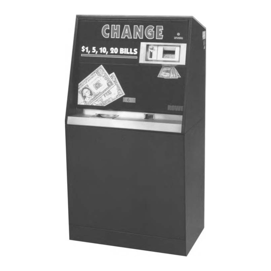
Section 1: System Description INTRODUCTION The Rowe BC-3500 Bill and Coin Changer is our top-of-the-line money changer that uses computer and money changer technology which combines Rowe quality and reliability with maximum flexibility and ease of installation and service. The BC-3500 accepts and dispenses change for combinations of quarters, half-dollars, and dollar coins as well as 1, 2, 5, 10, and 20 dollar bills of United States currency. -
Page 15: Changing Coins
FUNCTIONAL DESCRIPTION This functional description can be used to gain an overall understanding of the BC-3500 and its operation. Bill Transport The bill transport (see Figures 1-2 and 1-3) receives a bill as it is inserted by the customer. The bill is transported through the transporter on a belt system, carefully examined and , if the bill is determined to be valid, is delivered to the bill stacker. -
Page 16: Dual Bill Stacker
Section 1: System Description Figure 1-3. Bill Transport (Bottom View) Dual Bill Stacker The dual bill stacker in Figure 1-4 has the capability of stacking bills in two separate bill boxes. This feature allows the bill changer to alternate between the two bill boxes or to separate bills by denomination. -
Page 17: Coin Acceptor
BC-3500 Bill and Coin Changer • It holds the triac drive circuit and also activates the stacker monitor line to the CCC. • When the stacker completes its cycle, the cam switch opens, stopping the stacker motor and deactivating the monitor line to signal the CCC that it is ready for the next cycle. -
Page 18: Solid-State Coin Switches
Section 1: System Description Solid-State Coin Switches As a coin passes through a slot in the coin switch assembly with any mechanical coin acceptor, it momentarily interrupts an infrared light beam, causing a solid-state optical detector to send an electric pulse to the CCC. The duration of this pulse is then checked by the computer to determine its validity. -
Page 19: Coin Or Bill Return Button
An agitator, which is mounted on the drive shaft of each hopper, agitates the coin load to minimize coin jams in the hopper and ensure efficient coin pick up. To reduce jams and minimize the need for cleaning, the hoppers in the BC-3500 also have Teflon-coated coin tracks. 1 - 6... -
Page 20: Hopper Capacities
Section 1: System Description NOTE: The hoppers do not have an “Empty Sensor”. Empty hoppers are indicated by a failure to count the required number of coins in a specified period of time (approximately three minutes), however, if the changer shuts down frequently with an error relating to empty hoppers when they are not, then the “serpentine coin path”... -
Page 21: Temporarily Out Of Service Lamp
BC-3500 Bill and Coin Changer Temporarily Out of Service Lamp This lamp is located on the top door above the bill and coin inlet area. It lights whenever the machine is empty of change or shutdown due to some malfunction. In addition, the 40 VDC LED will normally go out if the out of service lamp is lit. -
Page 22: Emi Filter
Section 1: System Description EMI FILTER The ElectroMagnetic Interface (EMI) filter removes undesirable electrical noise from the incoming power line. The power transformer supplies 36 VAC and 22 VAC from which the rest of the system voltages are derived. POWER SUPPLY switch controls power to the machine. -
Page 23: Status Display
Section 4 of this manual. SERVICE AND CONTROL SWITCHES The BC-3500 Bill Changer’s service features and programming options are controlled by six switches. The descriptions that follow are introductory; follow the detailed procedures and instructions in Section 2 for specific operating and programming information. -
Page 24: Denominations Accepted
DENOMINATIONS ACCEPTED The BC-3500 can accept quarters, half-dollars, and dollar coins as well as 1, 2, 5, 10, and 20 dollar bills of United States currency. All of these denominations can be selected in combination with other denominations. However, due to mechanical limitations and other considerations, some combinations cannot be used. - Page 25 BC-3500 Bill and Coin Changer This page intentionally left blank. 1-12 25238801...
-
Page 26: Installation
Section 2: Installation & Programming INSTALLATION Installing the BC-3500 Bill and Coin Changer requires some instruction. For all types of installation, be sure that a power source is convenient and that the changer is mounted level. Always use a grounded (3-prong) outlet. - Page 27 ARE ATTACHED DIRECTLY TO THE WALL SCREW STUDS. Mounting Detail - Wood Frame Wall Mounting Detail - Masonry Wall CHANGER CONCRETE WALL STUD LEAD ANCHOR & LAG SCREW SCREW & WASHER Figure 2-2. Attaching the BC-3500 to a Wall 2 - 2 25238801...
-
Page 28: Change Payout Programming
Many different change combinations can be dispensed for the various denominations of money accepted. Change payout programming is accomplished using the five buttons on the CCC. As mentioned earlier, there are mechanical limitations which must be considered. The BC-3500 has three escrow buckets which will be preloaded with three different payout values. - Page 29 BC-3500 Bill and Coin Changer There are very few payout combinations which cannot be allowed. If you review them briefly, you will easily understand why they cannot be used. Table 2-2 lists those combinations: Table 2-2. Acceptance Combinations Which Are Not Allowed 50¢...
-
Page 30: Loading The Hoppers
Section 2: Installation & Programming LOADING THE HOPPERS Review Figure 2-4 before you begin. 1. Pull the hopper forward to its stop point. 2. Twist the top of a full coin bag one full turn. Grasp the twisted top with one hand and hold the bottom of the bag with the other. -
Page 31: Operational Information
BC-3500 Bill and Coin Changer Figure 2-4. Unloading the Hoppers 4. Hoppers may also be removed from the machine and inverted over the bag to empty. When replacing the hopper, be sure it is sitting securely in the pivot brackets and snug against the back plate. -
Page 32: Setting Up The Bc-3500
Section 2: Installation & Programming SETTING UP THE BC-3500 These steps should be followed to set up the BC-3500 to your requirements. If you do not follow these steps, the BC-3500 will remain all or partially programmed to the factory settings. -
Page 33: Normal Setup
BILL B CHECK ON button to select either . This is a security check made during the bill validation process. Rowe recommends the “ ” setting for all but the most extreme circumstances where a very high percentage of bills are rejected with Code “B”... -
Page 34: Switching To The Programming Mode
PROGRAMMING - - - - This is the display for entering the four-digit access code. Initially, the BC-3500 access code is set to 0000. This is a special access code in that no further entries are required to reach the setup functions described below –... -
Page 35: If An Access Code Has Been Established
IF AN ACCESS CODE HAS BEEN ESTABLISHED A. The left two digits of the access code will be blinking. (This is the BC-3500’s way of indicating which information will be changed if you make a change.) Press the ^ or button to change the left two digits of the four-digit access code. - Page 36 (- -), that hopper will not dispense any coins at any time. The computer must know the value of coins used for one important reason. The BC-3500 supports a “correct payout feature” – the computer simply will not allow you to program a payout that does not total the amount taken in unless you set at least one hopper value to tokens.
- Page 37 Ten Dollar Bill Twenty Dollar Bill Select only the denominations that you want to have the BC-3500 accept. If you try to select a denomination that would result in a combination which cannot be used, the computer will display the message “...
- Page 38 If you choose ernate, the BC-3500 stacker will stack one bill in the top bill box and the next bill in the bottom bill box regardless of the bill denomination. No further explanation is needed, go directly to Step 16 in this procedure.
- Page 39 ) provides maximum security against bogus BILL B CHECK ON bills. This is the factory setting and Rowe strongly recommends its use for all but the most severe environments. position improves acceptance of bills which are contaminated with metal chips or BILL B CHECK OFF dust, but also reduces protection against bogus bills.
-
Page 40: Self-Diagnostics
For more information on the reject messages, refer to Section 4: Troubleshooting. TRANSPORT SELF-CLEAR CHECK If a bill becomes jammed in the transport, the BC-3500 automatically tries to clear it out. To check out this feature: 25238801... -
Page 41: Acceptance Check
BC-3500 Bill and Coin Changer 1. Insert a bill into the transport upside down. The bill will be rejected and the status display should show “ ”. REJECT-BILL (A) 2. Hold the bill in the transport. Do not uncover the VI cell. Wait five seconds for the transport to start to cycle reverse-forward-reverse-forward-reverse. -
Page 42: Dispensing Tokens
Section 2: Installation & Programming DISPENSING TOKENS A unique situation exists when dispensing tokens while in the mode. The ability to payout a progressive bonus is allowed, even if payout is normally an extended vend of a lower denomination. Normally, in the mode or when paying out coins, some denominations require an extended dispense–direct NON-MC payout–replenish cycle. -
Page 43: Token Control
BC-3500 Bill and Coin Changer Token Control When dispensing tokens using the bonus payout, it is difficult to maintain token count control. The amount of money changed does not directly indicate the number of tokens dispensed. In the mode, a special token counter is used. -
Page 44: Accessing The Fast-Feed Menu
Section 2: Installation & Programming Note that the Fast-Feed information is maintained in memory until it is manually cleared by using the FUNCTION button. This applies even if another condition occurs. As an example, if the Fast-Feed Shutdown OUT OF SERVICE condition is entered at 11PM on Saturday and the changer returns to service 10 minutes later and continues to operate until 3PM on Sunday when it runs out of coins, the display will be flashing “... -
Page 45: Anti-Pullback System
BC-3500 Bill and Coin Changer 3. Use the ^ and buttons to establish the maximum number of bills to accept (“ ”), then press the HOPPER button and “ ” will begin flashing. Use the ^ and buttons to set the time lime (in minutes) for the changer to accept “... -
Page 46: Accessing The Anti-Pullback Menu
ERROR RESET MISCELLANEOUS The BC-3500 was designed to be simple and easy to troubleshoot. Please take time to study the operation of the machine and to study the explanations of the various status messages. The following is a list of incidental characteristics that may be of interest to the operator and service person: 1. - Page 47 4. If power is disrupted during a dispense or replenish cycle, the machine will immediately reset upon power turn on. There will be an incorrect change load in one of the buckets. This is the same as all previous Rowe changers.
- Page 48 Section 3: Routine Service INTRODUCTION In order to maintain control over money used for change dispensing, each changer should be loaded with a predetermined amount of cash. The inventory should be checked monthly as a precaution against malfunction and theft. Inventory control is most easily accomplished by using the replacement method of servicing. Using this method, all bills and coins are removed by the route man and the empty hoppers are refilled with a predetermined amount of change.
-
Page 49: Filling And Emptying The Bc-3500
BC-3500 Bill and Coin Changer 7. The magnetic head must have a bevelled edge on both front and back to keep both bill edges from becoming caught in forward or reverse. 8. Nylon rollers on the magnetic head assembly must rotate freely. No dirt, moisture, burrs, projections, or rough spots can be on the magnetic heads or magnetic head holder. -
Page 50: Emptying The Changer
Section 3: Routine Service EMPTYING THE CHANGER To empty the changer of all coins, first empty all hoppers according to instructions on the label on the top door. When the hoppers are emptied, some coins will remain in the change buckets. Press the test switches, one at a time, to release these remaining coins. -
Page 51: Cleaning The Hopper Coin Path
BC-3500 Bill and Coin Changer CLEANING THE HOPPER COIN PATH The coin tracks are Teflon coated to minimize dirt buildup. It may still be necessary to clean them at regular intervals, as dictated by the number of vends and the environment, to prevent dirt accumulation in the coin path. - Page 52 Section 3: Routine Service WARNING: Chain lubrication is not normally required or recommended. Do not use detergents to clean the hopper. The hopper has been factory lubricated and detergent cleaners may destroy this lubrication. Using the Nylon hopper cleaning brush supplied with each machine, remove all dirt from the angular sides and flat surfaces of the serpentine coin path as shown in Figure 3-4A.
-
Page 53: Change Bucket Lubrication
The coin dispenser change bucket door pivots, links, hubs and bell cranks are factory lubricated with light machine oil. Rowe specification Number 00137900 oil or 3-in-1 Electric Motor Oil can be used. If change bucket is worn beyond repair, order and install one of the kits listed at the end of the Parts Catalog in this manual. -
Page 54: Testing Bc-3500 Transport Photocells
4. One rotation of the motor drive shaft will produce 100 pulses. 5. If you were using the Anti-Pullback feature, be sure to re-enable it. Testing BC-3500 Transport Photocells The transport photocells are automatically checked each time the transport is turned on. Each photocell and light combination goes through a short test and brightness adjustment process. -
Page 55: Coin Counting Phototransistor (Detector) Check
BC-3500 Bill and Coin Changer Coin Counting Phototransistor (Detector) Check 1. Turn the bill changer switch POWER 2. Remove the black plastic cover from the phototransistor and connect the Common meter lead to the metal dispenser backing plate as shown in Figure 3-6A. -
Page 56: Adjustments
Section 3: Routine Service ADJUSTMENTS Bill and Coin Return Switch Assembly COIN INLET TO TOP DOOR CLEARANCE Make this adjustment if the gap between the bill and coin return switch plate and the door is excessive, or if the bill and coin return switch assembly has been removed. -
Page 57: Bill Return Switch Adjustment
BC-3500 Bill and Coin Changer BILL RETURN SWITCH ADJUSTMENT Refer to Figure 3-8 for this service check and adjustment. This switch must be in the actuated condition (the plunger is pushed in) when the machine is in standby and the button not depressed. - Page 58 Section 3: Routine Service 3. Tighten the three screws making sure the lower screw is tightened last. If a torque wrench is available, adjust the chain so that the torque input at the drive pin is one to four inch pounds. Figure 3-9.
-
Page 59: Adjsuting The Bill Acceptor Rails
BC-3500 Bill and Coin Changer Adjusting the Bill Acceptor Rails The bill acceptor mounting rails must be spaced correctly as shown in Figure 3-10A. The bill acceptor should slide in and out without binding, but not be sloppy in the rails. -
Page 60: Adjusting The Bill Transport To Stacker Alignment
Section 3: Routine Service Adjusting the Bill Transport To Stacker Alignment After adjusting the Coin Inlet To Top Door Clearance as described earlier in this section, loosen the two screws as shown in Figure 3-10B. With the bill acceptor flush with the coin inlet trim, pull the bill stacker as far forward as possible. - Page 61 BC-3500 Bill and Coin Changer Adjusting the Stacker Pusher Plate 1. Turn the power and remove the stacker from the changer. 2. Loosen the four mounting screws holding the motor plate as shown in Figure 3-12. 3. Hold the motor brake (disengaged) and manually rotate the motor shaft until the cam activates the stacker switch.
-
Page 62: Adjusting The Upper Bill Box
Section 3: Routine Service Adjusting the Upper Bill Box Refer to Figure 3-13 as you do the following four steps. 1. Make sure that the upper bill box (C) is tight against chute guides (A). If it is not, do the following procedure: 2. -
Page 63: Bill Stop Flipper Check
BC-3500 Bill and Coin Changer Bill Stop Flipper Check Refer to Figure 3-14 as an aid in doing this service check. 1. The bill stop flipper (A) must touch the tab (B) on the upper bill box. 2. With the lower bill box removed, slide the upper bill box into the stacker. The flipper should move downward approximately 1/32 to 1/16 inch when the upper bill box is inserted completely into the stacker. -
Page 64: Adjusting The Bill Stop Flipper
Section 3: Routine Service Adjusting the Bill Stop Flipper Refer to Figure 3-15 while you are doing this procedure. 1. The position of the bill stop flipper (A), can be adjusted by prying against the solenoid plunger stop tab (B) through the flipper opening in the pusher plate with a screwdriver (Service tip: Pry up on the stop tab (B) to lower the flipper;... - Page 65 BC-3500 Bill and Coin Changer 2. Adjust the lower bill box stop bracket and mounting plate so that the bottom bill box is aligned with the upper bill box and chute guides by: A. Loosen the two 8-32 screws (A) holding the mounting plate (C) to the stacker.
- Page 66 Section 3: Routine Service 7. If the upper bill box does not push into the latched position, bend the spring wire out far enough to ensure that the spring wire pushes the upper bill box in far enough to allow the bail wire (C) to fall and latch the bill box in place when the door is closed.
-
Page 67: Timing Belt Tension
BC-3500 Bill and Coin Changer Timing Belt Tension Refer to Figure 3-18 for this adjustment procedure. 1. Loosen the two screws (A) holding the belt tension adjustment levers (B) on both sides of the bill acceptor transport. 2. Make sure that the adjustment levers, adjusting roller, and shaft move freely. - Page 68 POWER UP DIAGNOSTICS As power is applied to the BC-3500, a series of power up checks are performed by the control computer before the machine is put into service. The 16-character alphanumeric status display on the control computer is the primary diagnostic indicator.
-
Page 69: Sequence Descriptions
If the machine code OFF, does not match (a CCC board from a BC-1200 installed in a BC-3500), the display will show “ MACHINE ”. If the configuration changed due to low battery voltage or some other reason effecting the RAM, CODE ERR the display will show “... -
Page 70: Accept, Payout, And Replenish Modes
Section 4: Troubleshooting Accept, Payout, and Replenish Modes During normal operation, the display will reflect each state the machine goes through as it happens. When a bill is moving in the transport, the message “ ” will appear. After validation, during the stack and vend cycles, VALIDATING the display will show the message “... -
Page 71: Index To Error Messages And Troubleshooting Charts
BC-3500 Bill and Coin Changer Index to Error Messages and Troubleshooting Charts +5 VDC Failure, +5 VDC LED Out 4-63 ........................................................Bill Changer Gives Erratic Payout for Bills and Coins (No Error Messages) ......................................4-61 Bill Changer Steals Bills (Works OK With Coins) ....................................4-59 Bill Changer Steals Bills and Coins (Gives No Change) ...................................... - Page 72 Section 4: Troubleshooting ERROR ?? ........................................4-38 EXTRA COIN - C HOP ....................................4-40 EXTRA COIN - L HOP ...................................... 4-40 EXTRA COIN - R HOP ..................................... 4-41 HOPPERS EMPTY ......................................4-46 L DETCTR ON LONG ...................................... 4-34 L HOPPER EMPTY ......................................4-43 One or More Hopper Motors Fail to Run 4-56 .....................................................
-
Page 73: Validation Rejects
BC-3500 Bill and Coin Changer VALIDATION REJECTS Cell Sequence Rejects REJECT - SHORT VI Symptom: The inlet cell was covered for too short of a time. This is a reject message. The bill was rejected because the VI cell was not covered long enough. The bill may have been torn on the right side, torn, or folded over at the trailing edge of the bill. - Page 74 Section 4: Troubleshooting REJECT - SHORT VF Symptom: Flipper cell covered for too short a time. This is a reject message. The bill was rejected because the flipper cell was uncovered too soon and the CCC recognized this as a non-valid validation sequence.
- Page 75 BC-3500 Bill and Coin Changer REJECT - VI AGAIN Symptom: A second bill was inserted while validating the first bill. This is a reject message. A bill was rejected because the VI cell was covered while the changer was in the process of validating a bill.
- Page 76 Section 4: Troubleshooting REJECT - TIMEOUT Symptom: Inlet cell was never uncovered. This is a reject message. The bill was rejected because the VI cell never uncovered. The CCC recognized this as a non-valid validation sequence. Take the following corrective action if bills are rejected frequently with this code. Corrective Action: 1.
- Page 77 BC-3500 Bill and Coin Changer REJECT - LONG VI Symptom: The inlet cell was covered for too long a time. This is a reject message. The bill was rejected because the VF cell was covered too soon, or the VI cell was covered too long.
- Page 78 Section 4: Troubleshooting REJECT - VT AGAIN Symptom: The transmissive cell was covered. This is a reject message. A bill was rejected because the VT cell recovered while the bill changer was in the process of validating a bill. If bills are rejected frequently with this message, check for a piece of paper or other material in the transport. The VT cell may be giving an intermittent signal.
- Page 79 BC-3500 Bill and Coin Changer REJECT - NO MAG Symptom: Not enough magnetic signal from the Mag. Amp. This is a reject message. The bill was rejected because no signals came from the Mag. Amp. The bill may have been inserted upside down.
- Page 80 Section 4: Troubleshooting REJECT - LATE VF Symptom: The flipper cell did not cover. This is a reject message. The bill was rejected because the VF cell was not covered soon enough after the VT cell was covered. The bill is possibly torn at its leading edge. An object is possibly hung-up or jammed in the track.
- Page 81 BC-3500 Bill and Coin Changer REJECT - SPEED Symptom: The transport motor speed is not correct. This is a reject message. The bill was rejected because the transport motor did not run at a constant speed during validation. Corrective Action: 1.
- Page 82 Section 4: Troubleshooting REJECT - LOST TACH Symptom: The tach signal from the transport was lost. This is a reject message. The bill was rejected because the CCC cannot control the transport motor speed without a tach. signal. Corrective Action: 1.
-
Page 83: Bill Parameter Rejects
BC-3500 Bill and Coin Changer BILL PARAMETER REJECTS Take corrective action only if all bills or a significant number of bills reject for the same reason. Be sure to try different bills and bills of different denominations. If they accept, the bill being rejected has some property the CCC finds abnormal. - Page 84 Section 4: Troubleshooting REJECT - BILL (D) Symptom: The bill failed validation. Corrective Action: 1. Replace the Mag. amp/transport 2. Replace the CCC. REJECT - BILL (E) Symptom: The bill failed validation. Corrective Action: 1. Check the VR/VT cells for proper voltages and switching (refer to Section 3). 2.
- Page 85 BC-3500 Bill and Coin Changer REJECT - BILL (H) Symptom: The bill failed validation because the information from Mag Head 2 was incorrect. Corrective Action: 1. Check the White/Green wire from the transport for an Open/Short to the CCC (P4 - Pin 5).
- Page 86 Section 4: Troubleshooting REJECT - NO DENOM Symptom: Bills are rejected with this code when the validation tests cannot accurately determine the bill’s denomination. Corrective Action: 1. Replace the transport. 2. Replace the CCC. REJECT - FAST FEED Symptom: The bill is being rejected because its acceptance would exceed the limits established for the Fast-Feed Shutdown feature.
-
Page 87: Transport Errors
BC-3500 Bill and Coin Changer Transport Errors Transport errors are considered to be recoverable errors. That is, if the source of the error goes away, the machine will return to the normal mode all by itself. Transport errors are shown on the status display while they STANDBY are present. - Page 88 Section 4: Troubleshooting CK TRANSPORT VF Symptom: The transport flipper cell voltage is not within limits (0 to 2.00 volts). Corrective Action: 1. Check the Brown wire and connectors in the transport harness for an open/short back to the CCC (P4 Pin 7). 2.
-
Page 89: Machine Errors
BC-3500 Bill and Coin Changer Machine Errors There are two types of machine errors — Shutdown errors are errors which SHUTDOWN NON-SHUTDOWN. could cause damage to the machine or incorrect payouts. errors are errors involving coin NON-SHUTDOWN switches, test switches and the bill return switch. - Page 90 Section 4: Troubleshooting CK CTR TEST SW Symptom: The center switch was closed longer than three seconds. TEST Corrective Action: switch input is (or was) showing an incorrect signal. CENTER TEST In order to prevent spurious payouts, the CCC immediately locks out all switch inputs if it receives an incorrect TEST signal from one of the...
- Page 91 BC-3500 Bill and Coin Changer CK TEST SWITCHES Symptom: More than one switch was closed at the same time. TEST Corrective Action: More than one switch input is (or was) showing an incorrect signal. TEST In order to prevent spurious payouts, the CCC immediately locks out all...
- Page 92 Section 4: Troubleshooting Chart 010 — No Test Switch Response Display shows: CK LEFT TEST SW – OR – CK CTR TEST SW – OR – CK RIGHT TEST SW – OR – CK TEST SWITCHES The bill changer doesn't respond to the test switches because one of the TEST switch inputs to the computer is, or was, showing an incorrect signal.
-
Page 93: Coin Switch Errors
BC-3500 Bill and Coin Changer Changer Errors (Non-Shutdown) (Continued) COIN SWITCH ERRORS CK 25 COIN SWTCH Symptom: The 25¢ coin switch was closed too long. Corrective Action: The 25¢ coin switch input is (or was) showing an incorrect signal. In order to prevent spurious payouts, the CCC immediately locks out all coin switch inputs if it receives an incorrect signal from the coin switches. - Page 94 Section 4: Troubleshooting CK 50 COIN SWTCH Symptom: The 50¢/$1.00 coin switch was closed too long. Corrective Action: The 50¢ coin switch input is (or was) showing an incorrect signal. In order to prevent spurious payouts, the CCC immediately locks out all coin switch inputs if it receives an incorrect signal from the coin switches.
- Page 95 BC-3500 Bill and Coin Changer Chart 020 - Bill Changer Doesn’t Accept Coins - Works OK With Bills Display shows: CK 25 COIN SW – OR – CK 50/100 COIN SW – OR – CK COIN SWITCHES One or both of the con switch inputs to the CCC are, or were, showing an incorrect signal. Press the FUNCTION button. Does the message reappear? Check for an obstruction or other condition ...
-
Page 96: Bill Changer Errors (Shutdown)
Section 4: Troubleshooting CK BILL RETRN SW Symptom: The bill return switch was closed longer than 10 seconds. This error will disable the bill return function. All other changer functions continue to operate. Corrective Action: 1. Remove the bind or jam in the bill return linkage. 2. - Page 97 BC-3500 Bill and Coin Changer 4. If this message does not reappear after resetting the bill changer, check the wiring to the hopper motors and coin detectors. If no problems are found, replace the CCC. To restore the bill changer to operation, press button after correcting the problem.
- Page 98 Section 4: Troubleshooting NOTE: This error code may be the result of a leaky output to the left hopper drive motor from the CCC. If this is the case, replace the CCC. For a more complete troubleshooting sequence, refer to Troubleshooting Chart 030 at the end of this COIN DETECTOR troubleshooting.
- Page 99 BC-3500 Bill and Coin Changer CK COIN DETECTORS Symptom: More than one coin detector was blocked while the bill changer was in One of the buckets may have STANDBY. an incorrect change load, or one of the hopper motors may have been running in standby mode.
- Page 100 Section 4: Troubleshooting Chart 030 - Shutdown – Out Of Service Lamp Lit Display shows: CK L COIN DETCTR – OR – CK C COIN DETCTR – OR – CK R COIN DETCTR – OR – CK COIN DETCTRS One or more of the coin photodetectors is, or was, giving an incorrect signal. This happened when the bill changer was in STANDBY. An incorrect change load may be in ...
- Page 101 BC-3500 Bill and Coin Changer L DETCTR ON LONG Symptom: While replenishing, the left detector was blocked too long. Corrective Action: During the last replenish cycle, the system detected a coin pulse from the dispenser that was much longer than normal.
- Page 102 Section 4: Troubleshooting C DETCTR ON LONG Symptom: While replenishing, the center detector was blocked too long. Corrective Action: During the last replenish cycle, the system detected a coin pulse from the dispenser that was much longer than normal. Most likely, an incorrect change load has been deposited into one of the change buckets. 1.
- Page 103 BC-3500 Bill and Coin Changer R DETCTR ON LONG Symptom: While replenishing, the right detector was blocked too long. Corrective Action: During the last replenish cycle, the system detected a coin pulse from the dispenser that was much longer than normal.
- Page 104 Section 4: Troubleshooting DETCTRS ON LONG Symptom: While replenishing, more than one detector was blocked too long. Corrective Action: During the last replenish cycle, the system detected a coin pulse from the dispenser that was much longer than normal. Most likely, an incorrect change load has been deposited into one of the change buckets. 1.
- Page 105 BC-3500 Bill and Coin Changer CANNOT PAYOUT VALUE Symptom: Unable to pay out inserted combination. Corrective Action: Check to make sure the coin mechanism is wired correctly. Reset by pressing the button. FUNCTION ERROR ?? Symptom: Unknown error code xxx.
- Page 106 Section 4: Troubleshooting Chart 040 - Shutdown - Out Of Service Lamp Lit Display shows: L DETCTR ON LONG – OR – C DETCTR ON LONG – OR – R DETCTR ON LONG During the last replenish cycle, the system detected a coin pulse from the dispenser that was much longer than normal. Most likely, one of the change buckets has an incorrect change load.
- Page 107 BC-3500 Bill and Coin Changer EXTRA COIN - L HOP Symptom: More than one extra coin was detected passing through the left detector. Corrective Action: Since last time bill changer was reset, the bill changer may have dispensed two more coins than it should have during the replenish cycle.
- Page 108 Section 4: Troubleshooting EXTRA COIN - R HOP Symptom: More than one extra coin was detected passing through the right detector. Corrective Action: Since last time bill changer was reset, the bill changer may have dispensed two more coins than it should have during the replenish cycle.
- Page 109 BC-3500 Bill and Coin Changer Chart 050 - Shutdown - Out Of Service Lamp Lit Display shows: EXTRA COIN L HOP – OR – EXTRA COIN C HOP – OR – EXTRA COIN R HOP Since the last time the bill changer was reset, it may have dispensed two more coins than it should have.
- Page 110 Section 4: Troubleshooting L HOPPER EMPTY Symptom: The left hopper is empty. Corrective Action: The bill changer was shutdown because the count from the left-hand hopper was not satisfied within 180 seconds. One change bucket will have an incorrect change load from the left hopper. 1.
- Page 111 BC-3500 Bill and Coin Changer C HOPPER EMPTY Symptom: The center hopper is empty. Corrective Action: The bill changer was shutdown because the count from the center hopper was not satisfied within 180 seconds. One change bucket will have an incorrect change load from the center hopper.
- Page 112 Section 4: Troubleshooting R HOPPER EMPTY Symptom: The right hopper is empty. Corrective Action: The bill changer was shutdown because the count from the right-hand hopper was not satisfied within 180 seconds. One change bucket will have an incorrect change load from the right-hand hopper. 1.
- Page 113 BC-3500 Bill and Coin Changer HOPPERS EMPTY Symptom: All hoppers are empty ( mode message). Corrective Action: 1. Refill all the hoppers. 2. The changer shut down because the count could not be satisfied using any of the hoppers. 3. One change bucket will have an incorrect load.
-
Page 114: Mc Dispense Mode
Section 4: Troubleshooting Chart 060 - Shutdown - Out Of Service Lamp Lit Display shows: L HOPPER EMPTY – OR – C HOPPER EMPTY – OR – R HOPPER EMPTY – OR – HOPPERS EMPTY The changer was not shut down because the count from the hopper was not satisfied within 180 seconds. - Page 115 BC-3500 Bill and Coin Changer CK STACKER Symptom: The stacker did not return to the position. HOME If the machine is in SHUTDOWN and this message is showing, the bill stacker monitor input is active. 1. Leave the power . Disconnect the main harness at the bill stacker. Press the button.
- Page 116 Section 4: Troubleshooting Chart 070 - Shutdown - Out Of Service Lamp Lit Display shows: CK STACKER The bill stacker monitor line to the computer is active. Leave the power ON. Disconnect plug P501 at the side of the bill stacker. Press the FUNCTION button on the CCC. Does the machine return to service? Defective bill stacker. Replace with a new Check ...
- Page 117 BC-3500 Bill and Coin Changer BUCKET PWR FLT Symptom: One of the bucket coils was detected active when it should not be. Corrective Action: Machine has been shut down because one or more of the bucket solenoids were energized during standby. Most likely, one of the buckets has an incorrect change load.
- Page 118 Section 4: Troubleshooting Chart 080 - Shutdown - Out Of Service Lamp Lit Display shows: BUCKET PWR FLT One or more of the bucket solenoids was energized during STANDBY. Most likely, an incorrect change load is in one of the buckets. Press the FUNCTION button on the CCC. Does the message reappear? Check the R/B, Y/BR, BL/W, and V/O wires Unplug P2 from the CCC and press the from ...
- Page 119 BC-3500 Bill and Coin Changer BUCKET NOT OPEN Symptom: A bucket coil did not draw current when it was energized. This is a fault code. The machine has been shut down because one of the bucket solenoids failed to energize properly for a normal vend.
- Page 120 Section 4: Troubleshooting Chart 090 - Shutdown - Out Of Service Lamp Lit Display shows: BUCKET NOT OPEN One of the bucket solenoids failed to energize properly for a normal vend. Press the reset switch. Try several test vends from each of the three buckets. Does one cause a BUCKET NOT OPEN error message? Possible defective computer control center. Do all three buckets cause a BUCKET NOT OPEN error message? Intermittent open connection in the V/O, R/B, Y/BR, or BL/W wires. Check the wiring and solenoid Check the V/O wire for open associated with the bucket that connections ...
- Page 121 BC-3500 Bill and Coin Changer BUCKET STAYS ON Symptom: A bucket solenoid continued to draw current after it was de-energized. This is a fault code. The machine has been shut down because one of the bucket solenoids was energized too long during a normal vend.
- Page 122 Section 4: Troubleshooting Chart 100 - Shutdown - Out Of Service Lamp Lit Display shows: BUCKET STAYS ON One of the bucket solenoids was energized too long during a normal vend. Most likely, there is an incorrect change load in one of the buckets. Press the FUNCTION button.
- Page 123 BC-3500 Bill and Coin Changer One or More Hopper Motors Fail to Run Do any of the hopper motors run? Press the FUNCTION button and test vend using a Determine which motor does not run. Program to test dollar bill. Does the stacker operate? for $1.00. Does the display indicate HOPPER PROBLEMS? Check for an open circuit Stuck contact on the power ...
- Page 124 Section 4: Troubleshooting Bill Transport Fails to Run in One or Both Directions (Works OK for Coins and Test Switches) Does the transport run in one direction? Does the motor hum? Does the transport run forward? Cover the VI cell. Does the transport run Check the wire from J202 Are the timing belts...
- Page 125 BC-3500 Bill and Coin Changer Bill Changer Steals Coins - Works OK with Bills How often does this happen? Intermittent Continuous Intermittent open circuit in the wiring to the Does the display show a COIN ERROR? coin switch board. Check B, BL, W/BR, and R wires to the coin acceptor. Are all denominations Does the vend counter of coins being stolen? operate? Broken, bound, or worn bucket assembly. No +5VDC or ...
- Page 126 Section 4: Troubleshooting Bill Changer Steals Bills - Works OK with Coins How often does this happen? Intermittent Continuous Sticky VF flipper at the back of the Does this happen with all escrow vends? transport. ONLY ONE Broken, bound, or Does the vend counter warn bucket assembly. operate? Broken, bound, or worn bucket assembly. Shorted (less than 7 Defective CCC.
- Page 127 BC-3500 Bill and Coin Changer Bill Changer Steals Bills and Coins (Gives No Change) How often does this happen? Intermittent Continuous Broken, bound, or worn bucket assembly. Broken, bound, or worn bucket assembly. Defective +40VDC supply at J204 pin 3. Intermittent 12VDC failure to the board. Replace the power supply board on the ...
- Page 128 Section 4: Troubleshooting Bill Changer Gives Erratic Payout for Bills and Coins (No Error Messages) Do erratic payouts often occur in succession, with one making up shortage from the previous vend? Check for coin hangup in the upper coin Broken, bound, or worn bucket assembly. chute, lower coin chute, and in the coin bucket.
- Page 129 BC-3500 Bill and Coin Changer Bill Stacker Problems Does the stacker motor run at all? In addition to the steps at the left, check The stacker cam switches are out of the following: adjustment. adjustment procedures in Section 3 of this manual.
- Page 130 Section 4: Troubleshooting +5 VDC Failure, +5 VDC LED Out Is the +12VDC LED out? Turn the power OFF, unplug P203, and allow VR802 to cool Is the +30VDC LED out? approximately 4-5 minutes. Turn the power ON (with P203 still unplugged). Does the +5VDC LED come ON? Defective power supply Defective power supply board A short to Ground exists in (not board). Replace the in the power control center. the +5V lines (Blue wires) power control center. at the dispenser, transport, or in the main machine harness.
-
Page 131: Detailed Control Computer Board Operation
Rowe suggests that you send any defective CCC boards back to the factory for proper servicing. Figure 4-5 is a four-sheet schematic of the 65077458 Changer Control Computer board. Sheet 1 shows the microprocessor, memory, and address decoding circuits. -
Page 132: I/O Ports
The interface circuits for these functions are contained on sheet 3. U16 is an RS485 interface chip allowing communication to test equipment and the Rowe BC programming aid. U15 is an EPROM used to store information that must be kept, even if the battery voltage to the RAM dies. Original date of manufacture, programming information, and other things are stored in the EPROM. -
Page 133: Output Circuits
BC-3500 Bill and Coin Changer Sheet 3: Output Circuits All output circuits, except the transport transmissive/reflective LED driver circuit, are inactive when the switched +12 VDC supply is . This keeps all the motors, solenoids, and coils in the machine from operating when the machine... -
Page 134: Out Of Service Lamp
Section 4: Troubleshooting OUT OF SERVICE LAMP lamp is controlled by the switched +12 VDC supply through U7G Pins 7 and 10. Whenever OUT OF SERVICE the switched +12 VDC supply is , the power control relay is energized and the lamp is OUT OF SERVICE Whenever the switched 12 VDC supply is turned... - Page 135 BC-3500 Bill and Coin Changer LOGIC BOARD 45076402-CKT. BD. ASSY. INTERCONNECT SHIELD SHIELD TRANSPORT MOTOR + TRANSPORT MOTOR - W/BL COIN LOCKOUT COIL HOPPER MOTOR RIGHT HOPPER MOTOR CENTER HOPPER MOTOR LEFT LED DRIVE STACKER DRIVE Y/BR BUCKET DRIVE LEFT BUCKET DRIVE CENTER J402 P402 BL/W BUCKET DRIVE RIGHT POWER CONTROL RELAY DOLLARS ACCEPTED D401 BL/Y STACKER SOLENOID O/BR Y/BR D402 BL/W D403 COIN DETECTOR LEFT W/BR MAG HEAD 1 MAG HEAD 2 TRANSMISSIVE CELL FLIPPER CELL...
- Page 136 R503 100 KΩ 2.2 KΩ D502 DRIVER BOARD 65046701 BILL STACKER ASS'Y 65046801 D305 L301 COIN LOCKOUT COIL P/J301 W/BL R305 R302 W/BR Q303 Q304 D302 D301 D303 D304 R303 R304 C301 C302 Q302 Q301 R301 = EARTH (FAULT) GROUND SOLID STATE COIN SWITCH 45048203 = LOW CURRENT GROUND COIN ACCEPTOR AND BRACKET ASS'Y 35026107 Figure 4-1. BC-3500 Schematic Diagram 25238801 4-69...
- Page 137 BC-3500 Bill and Coin Changer 4-70 25238801...
- Page 138 Section 4: Troubleshooting Figure 4-1. BC-3500 Wiring Diagram 25238801 4-71...
- Page 139 BC-3500 Bill and Coin Changer CB202 36 VAC 120 VAC HOT CB204 2 AMP TO P806 5 AMP 120 VAC NEUTRAL 22 VAC CB203 7 AMP 45059505-POWER TRANSFORMER J802 P802 D818 D807 VR804 +14.8 VDC L804 C803 C812 OUTPUT 6800 µF 220 µF \ON/ OFF @ 35V @ 35V R801 FEEDBACK 1.2 KΩ D814 LM2576T-ADJ R824 D801 12 VDC 22.1 KΩ, 1%...
- Page 140 Section 4: Troubleshooting P803 J803 J202 12 VDC 8 VDC COMMON C814 COMMON COMMON .33 µF POWER GROUND @ 50V COMMON DISPENSER COMMON TRANSPORT GROUND STACKER COMMON COIN ACCEPTOR COMMON BR/Y OUT OF SERVICE LAMP 45074702 HARNESS ASSEMBLY J203 P804 J804 5 VDC - UNUSED 5 VDC - DISPENSER 5 VDC - TRANSPORT 5 VDC - COIN ACCEPTOR SWITCHED 30 VDC STACKER SWITCHED 30 VDC COIN ACCEPTOR 45074701 HARNESS ASSEMBLY C808 22 µF R802 @ 10V 470 Ω D802 5 VDC P806 J806 J201...
- Page 141 BC-3500 Bill and Coin Changer P802 D818 D807 VR804 +14.8 VDC L804 C803 C812 OUTPUT 6800 µF 220 µF @ 35V @ 35V \ON/ OFF FEEDBACK D814 LM2576T-ADJ R824 22.1 KΩ, 1% R829 R825 2 KΩ, 1% 10KΩ R831 Q802 100 KΩ R830 2 KΩ D816 VR803 +8 VDC L803 R828 OUTPUT \ON/ OFF FEEDBACK 10KΩ...
- Page 142 Section 4: Troubleshooting P803 12 VDC 8 VDC C814 .33 µF @ 50V POWER GROUND R801 COMMON 1.2 KΩ TRANSPORT GROUND OUT OF SERVICE LAMP D801 12 VDC C810 2200 µF @ 16V P804 5 VDC D812 SWITCHED 30 VDC VR802 REG. FIXED +5V C807 C808 1000 µF 22 µF R802 @ 10V @ 10V 470 Ω D802 5 VDC P807 120 VAC SWITCHED 120 VAC HOT C809 2200 uF @ 16V P805...
-
Page 143: Power Supply Circuit Board
BC-3500 Bill and Coin Changer Power Supply Circuit Board Assembly - 65069203 (Rev. A) C801 Capacitor - Electrolytic 50 VDC 4.7 µF 70023806 C802 Capacitor - Electrolytic 50 VDC 4.7 µF 70023806 C803 Capacitor - Electrolytic 35 VDC 6800 µF... - Page 144 Section 4: Troubleshooting Q801 Transistor - NPN MPSA06 70030008 Q802 Transistor - NPN MPSA06 70030008 Note: All resistors are ¼ watt 5%, unless otherwise noted. R801 Resistor - Carbon Film 1.2 kΩ 79901122 470 Ω R802 Resistor - Carbon Film 79901471 R803 Resistor - Carbon Film 1/2 W 5%...
- Page 145 BC-3500 Bill and Coin Changer 45072801 - CKT. BD. ASS'Y MAG. AMP. J601 BLACK GROUND YELLOW HEAD 1 ORANGE HEAD 2 BLUE +5 VDC WH/VIOLET WH/BROWN 35049004 - MAGNETIC HEAD (DUAL FULL TRACK) R714 TRANSMISSIVE SENSOR REFLECTIVE SENSOR D703 R713 R715 330kΩ C705 J703 P703 .22µF BLUE ORANGE BROWN 45058205 D702 HARNESS & BOARD ASSEMBLY INLET SENSOR...
- Page 146 Section 4: Troubleshooting 45058408 - MOTOR ASS'Y (BA-50) +5 VDC WHITE ANODE ORANGE OUTPUT BLUE GROUND GREEN M701 BLACK 1 2 3 4 5 6 J702 P702 5 VDC 5 VDC 1 2 3 4 5 6 R705 R706 220 Ω 5.6KΩ Q701 W705 D701 W704 5 VDC 5 VDC R708 C701 220 Ω...
- Page 147 BC-3500 Bill and Coin Changer Interconnect Circuit Board Assembly - 45073001 (Rev. D) C701 Capacitor - Ceramic 50 VDC .1 µF 70028511 C702 Capacitor - Mylar 100 VDC 1.0 µF 70021561 C703 Capacitor - Mylar 100 VDC .33 µF 70021555...
- Page 148 Section 4: Troubleshooting This page intentionally left blank. 25238801 4-81...
- Page 149 BC-3500 Bill and Coin Changer 4-82 25238801...
- Page 150 Section 4: Troubleshooting Figure 4-4. Schematic Diagram - Magnetic Amplifier Board 25238801 4-83...
- Page 151 Magnetic Amplifier Circuit Board 45072801 (Rev. E) NOTE: This components list is intended as a troubleshooting aid only. Rowe does not recommend replacement of any magnetic amplifier circuit board components. Replacing components on this circuit board may damage the magnetic head.
- Page 152 Section 4: Troubleshooting Note: All resistors are ¼ watt 5%, unless otherwise noted. R601 Resistor - Carbon Film 1/8 W 1% 1.5 kΩ 799101501 R602 Resistor - Carbon Film 1/8 W 1% 332 kΩ 799103323 100 Ω R603 Resistor - Carbon Film 79911101 100 Ω...
- Page 153 BC-3500 Bill and Coin Changer AD [ 0..7 ] 5 VDC A [ 0..15 ] R156 10KΩ 12 VDC SWITCHED 12 VDC U12A U14F MPS6521 MPSA56 R157 74HCT00 7406 8.2KΩ R108 10KΩ MPS6521 U12B 5 VDC R158 680 OHM 1/2W MPS6521 R107 74HCT00 2KΩ 2N4124 1KΩ IN4004 8 VDC LM340T5 10KΩ INPUT RESET 34064 .33 µF...
- Page 154 Section 4: Troubleshooting 5 VDC 10KΩ FOR PROGRAM MEMORY, 5 VDC 10KΩ SOCKET XU18 TO PIGGYBACK BOARD 10KΩ MACHINE CODE 0 R109 4.7KΩ MACHINE CODE 1 10KΩ 10KΩ 10KΩ VBAT DOWN 74HCT244 6264_CMOS RAM FUNCTION VCC/CE2 HOPPER 10KΩ VALUE NORMAL / PROGRAM WE/A11 E000- FFFF OUTPUT CIRCUITS ( C200 ) HOPPER MOTOR LEFT HOPPER MOTOR CENTER ( C100 ) HOPPER MOTOR RIGHT U12C MONEY COUNTER COIN LOCKOUT COIL 74HCT00 74HCT138 STACKER DRIVE...
- Page 155 BC-3500 Bill and Coin Changer 30 VDC 5 VDC 2.2KΩ 4.7KΩ U14A 4.7KΩ DISPLAY RESET 7406 5 VDC 2003 4.7KΩ 2.2KΩ U14B 4.7KΩ DISPLAY DATA 7406 2003 5 VDC 2.2KΩ 4.7KΩ U14C 4.7KΩ DISPLAY CLOCK 7406 2003 30 VDC IN4745A - 16V 47 µF 470 OHM XU18 I/O/Q I/O/Q TO SOCKET U18 I/O/Q I/O/Q ON MAIN BOARD...
- Page 156 Section 4: Troubleshooting 220KΩ 220KΩ 220KΩ 220KΩ 220KΩ 220KΩ 220KΩ 220KΩ 220KΩ 220KΩ 220KΩ 220KΩ 30 VDC 220KΩ POINT TAIL 220KΩ SEG P 330 OHM SEG O 20KΩ DATA SEG N SCLK SEG M SEG L SEG K SEG J SEG I SEG H SEG G SEG F SEG E SEG D SEG C SEG B SEG A IN4734 - 5.6V DIGIT 1 DIGIT 2...
- Page 157 BC-3500 Bill and Coin Changer 12 VDC TIP115 12 VDC SWITCHED 1N4004 10KΩ 10KΩ U11G 820 OHM TRANSPORT MOTOR DRIVE 7407 2003 12 VDC SWITCHED 12 VDC 10KΩ 1N4004 RELAY DPDT TRANSPORT MOTOR DIRECTION 7407 2003 12 VDC 1N4004 1N4004 12 VDC SWITCHED 150 OHM 1/2W 220 OHM U11A T2500D 3021 .01 µF HOPPER MOTOR LEFT 2003 1.5KΩ 12 VDC SWITCHED 150 OHM 1/2W 220 OHM...
- Page 158 Section 4: Troubleshooting VS DRIVE (NOT USED) 7406 U14D LED DRIVE 7406 12 VDC SWITCHED LED DRIVE STACKER DRIVE 10KΩ BUCKET DRIVE LEFT BUCKET DRIVE CENTER 2003 BUCKET DRIVE RIGHT POWER CONTROL RELAY 12 VDC SWITCHED DOLLARS ACCEPTED STACKER SOLENOID U12D U14E 10KΩ 100 OHM STACKER DRIVE 74HCT00 7406 12 VDC SWITCHED 7407 2003 10KΩ DOLLARS ACCEPTED 12 VDC SWITCHED R104 MPSA56 150 OHM R106 10KΩ TIP102 U11D BUCKET DRIVE LEFT R103...
- Page 159 BC-3500 Bill and Coin Changer R110 5 VDC 47 OHM U17A COIN DETECTOR LEFT R130 R111 10KΩ 1KΩ MAG HEAD 1 PULSE .1 µF 74HC14 R127 R129 .1 µF 1KΩ 10KΩ NPN - MPS6521 5 VDC R117 1 KΩ R128 100KΩ 1N4148 .033 µF R116 1 KΩ TEST SWITCH LEFT 5 VDC R123 R134 1 µF 1 KΩ 1KΩ MAG HEAD 1 ANALOG R122 1 KΩ...
- Page 160 Section 4: Troubleshooting 5 VDC R137 4.7KΩ R148 100 OHM MACHINE CODE 0 .1 µF 5 VDC R138 4.7KΩ R149 100 OHM MACHINE CODE 1 .1 µF R113 47 OHM COIN DETECTOR CENTER COIN DETECTOR RIGHT R115 47 OHM R112 R114 .1 µF .1 µF 1KΩ 1KΩ 5 VDC R119 4.7KΩ R118 100 OHM ACCEPTOR COIN 2 5 VDC R120 .1 µF 4.7KΩ R121 100 OHM ACCEPTOR COIN 1 .1 µF...
-
Page 161: Computer Control Board
BC-3500 Bill and Coin Changer Computer Control Board 65077450 (Rev. C) Battery - Rechargeable 30763103 Capacitor - Ceramic Disc 1 kV 20% .01 µF 70022508 Capacitor - Ceramic Disc 1 kV 20% .01 µF 70022508 Capacitor - Ceramic Disc 1 kV 20% .01 µF... - Page 162 Section 4: Troubleshooting Capacitor - Monolithic Ceramic .1 µF 70028511 Capacitor - Monolithic Ceramic .1 µF 70028511 Capacitor - Monolithic Ceramic 20% .1 µF 70028514 Capacitor - Monolithic Ceramic 20% .033 µF 70028506 Capacitor - Tantalum 47 pF 70025102 Capacitor - Tantalum 47 pF 70025102 Capacitor - Electrolytic 35 VDC 20%...
- Page 163 BC-3500 Bill and Coin Changer Computer Control Board 65077450 (continued) Transistor - Silicon PNP MPSA56 70030104 Transistor - Silicon PNP See NOTE 3 Transistor - Silicon NPN MPS6521 70030007 Transistor - Silicon PNP MPSA56 70030104 Transistor - Silicon NPN MPS6521...
- Page 164 Section 4: Troubleshooting Resistor - Carbon Film 1/8W 5% 220 kΩ 79905224 Resistor - Carbon Film 1/8W 5% 220 kΩ 79905224 Resistor - Carbon Film 1/8W 5% 220 kΩ 79905224 Resistor - Carbon Film 1/8W 5% 220 kΩ 79905224 Resistor - Carbon Film 1/8W 5% 220 kΩ...
- Page 165 BC-3500 Bill and Coin Changer Computer Control Board 65077450 (continued) Resistor - Carbon Film 1/4W 5% 10 kΩ 79901103 Resistor - Carbon Film 1/4W 5% 10 kΩ 79901103 Resistor - Carbon Film 1/4W 5% 4.7 kΩ 79901472 Resistor - Carbon Film 1/4W 5% 4.7 kΩ...
- Page 166 Section 4: Troubleshooting R129 Resistor - Carbon Film 1/4W 5% 10 kΩ 79901103 R130 Resistor - Carbon Film 1/4W 5% 10 kΩ 79901103 R131 Resistor - Carbon Film 1/4W 5% 10 kΩ 79901103 100 Ω R132 Resistor - Carbon Film 1/4W 5% 79901101 R133 Resistor - Carbon Film 1/4W 5%...
- Page 167 BC-3500 Bill and Coin Changer Computer Control Board 65077450 (continued) I.C. - TTL Hex Buffer O.C. 7407 70036309 I.C. - Darlington Array ULN2003 70036901 I.C. - Octal Buffer 74HCT244 79930244 I.C. - Octal Transparent Latch 74HCT373 79930373 I.C. - 32K X 8 CMOS RAM...
- Page 168 Section 4: Troubleshooting This page intentionally left blank. 25238801 4-101...
- Page 169 BC-3500 Bill and Coin Changer Figure 4-6. Stacker Driver Circuit Board Schematic 4-102 25238801...
-
Page 170: Bill Stacker Driver Circuit Board
Section 4: Troubleshooting Bill Stacker Driver Circuit Board 65046701 (Rev. L) Capacitor - Electrolytic 50 VDC 4.7 µF 70023806 Capacitor - Mylar 630 VDC .022 µF 70021609 Capacitor - Mylar 630 VDC .022 µF 70021609 Diode - Silicon 70035005 Diode - Silicon 70035007 Diode - Silicon 70035101... - Page 171 BC-3500 Bill and Coin Changer R303 Coin "B" CR304 50¢ & $1.00 150 KΩ Large Slot Q304 CR302 Q302 R304 C302 150 KΩ .1 µF R302 150 KΩ Coin "A" CR303 25¢ Small Slot CR301 Q303 Q301 R301 C301 150 KΩ .1 µF R301 100 Ω Figure 4-7. Schematic Diagram - Coin Switch...
-
Page 172: Coin Switch Circuit Board
Section 4: Troubleshooting Coin Switch Circuit Board 45048203 (Rev. L) C301 Capacitor - Monolithic .1 µF 70028514 C302 Capacitor - Monolithic .1 µF 70028514 CR301/ Sensor/LED Pair 70033501 Q301 CR302/ Sensor/LED Pair 70033501 Q302 CR303 Diode - Silicon 70035007 CR304 Diode - Silicon 70035007 Q303... - Page 173 BC-3500 Bill and Coin Changer 35134401 C.B. ASSY COIN ACCEPTOR INTERFACE CHANGER COIN ACCEPTOR +12 VDC COMMON ENABLE COIN 3 UNUSED COIN 1 COIN 1 COIN 2 COIN 2 COIN 4 UNUSED Figure 4-9. Electric Coin Acceptor Interface 35134401 4-106...
- Page 174 Section 4: Troubleshooting Circuit Board Assembly - Electronic Coin Acceptor Interface 35134401 Capacitor - Monoceramic .1 µF 70028514 Polarizing Wafer (90°) 8 Circuits 70076008 Terminal Strip (.100) - Double Row (90°) 70089535 Resistor 1/4W 5% 10 kΩ 79901103 25238801 4-107...
- Page 175 BC-3500 Bill and Coin Changer Interconnect Circuit Board Assembly - 45076402 (Rev. B) Diode - Silicon 70035006 Diode - Silicon 70035006 Diode - Silicon 70035006 Wafer - Polarizing 7 Circuit 70075007 Wafer - Polarizing 15 Circuit 70080515 Wafer - Polarizing...
-
Page 176: Harness Color Coding
HARNESS COLOR CODING Harness wiring in the BC-3500 is color coded according to function. To check wiring in the machine, find the function you want in the chart below and not the wire color associated with this function. Then, check this color wiring to find the source of the problem. - Page 177 BC-3500 Bill and Coin Changer FUNCTIONS WIRE COLOR SUPPLY VOLTAGES 120 VAC Hot Black/White 120 AC Common White +40 VDC Sensed Violet/Orange +30 VDC +5 VDC to out of service lamp Brown/Yellow +12 VDC Violet +8 VDC Slate +5 VDC...
- Page 178 Section 5: Additional Information FUNCTIONS WIRE COLOR Coin Switch Assembly: Coin Lockout Coil White/Blue 25¢ Coin Switch White/Brown 50¢/$1.00 Coin Switch White/Yellow Dispenser: Left Coin Detector Orange/Green Center Coin Detector Orange/Brown Right Coin Detector Orange/Black Left Hopper Motor Black/Red Center Hopper Motor Brown Right Hopper Motor Black/Yellow...
- Page 179 BC-3500 Bill and Coin Changer This page intentionally left blank. 5 - 4 25238801...
- Page 180 Catalog Description ......................6-3 Parts List Description ......................6-3 Ordering Replacement Parts .....................6-3 PARTS CATALOG Model BC-3500 Bill and Coin Changer Assembly ..............6-4 Replacement Cabinet Part Nos....................6-6 Top Cabinet Assembly ......................6-8 Top Cabinet Door Assembly ....................6-12 Base Cabinet Assembly ...................... 6-14 BA-50 Bill Acceptor Assembly .....................
- Page 181 6 - 2 25238801...
-
Page 182: Parts Catalog
INTRODUCTION This parts catalog lists replacement parts for the BC-3500. The purpose of this parts catalog is to locate and identify replaceable components and supply information on how to order them. Catalog Description This catalog is divided into major sections labeled with figure numbers, which correspond to the illustrations used. - Page 183 Figure 6-1. Bill and Changer Assembly 6 - 4 25238801...
- Page 184 • • BC-3500 Bill Insertion Label ($1 & $5) ................1 25070233 • • BC-3500 Bill Insertion Label ($1, 5, 10) ................1 25070234 • • BC-3500 Bill Insertion Label ($1, 5, 10, 20) ............... 1 27027204 • • Coin Block Bracket ......................1 25081202 •...
- Page 185 Table 6-1. Replacement Cabinet Parts Numbers Top Cabinet Assembly (without Door) See Figure 6-2, Sheet 1 and 2 65047002 Top Cabinet Weld Assembly - White 65047003 Top Cabinet Weld Assembly - Black Front Door Assembly - See Figure 6-3 65047502 Door Assembly - Blue 65047503 Door Assembly - White...
- Page 186 Standard Top Door “New Style” Top Door 25238801 6 - 7...
- Page 187 Figure 6-2. Top Cabinet Assembly Sheet 1 6 - 8 25238801...
- Page 188 Figure 6-2. Top Cabinet Assembly (Sheet 1) Ref. Part No. Description Ref. BC-3500 Top Cabinet Assembly 21357804 • Nut - Elastic Stop (1/4-20) ....................1 70121408 • Spacer ..........................1 35034406 • Door Support Assembly ..................... 1 35032804 • • Pivot Bar Assembly ......................1 35032905 •...
- Page 189 Figure 6-2. Top Cabinet Assembly Sheet 2 8, 10 4, 5, 6, 7 6 - 1 0 25238801...
- Page 190 Figure 6-2. Top Cabinet Assembly (Sheet 2) Ref. Part No. Description Ref. BC-3500 Top Cabinet Assembly 45016710 • Coin Inlet and Chute Assembly (5.5” wide) ................. 1 45016712 • Coin Inlet and Chute Assembly (3.5” wide) ................. 1 35118801 • Harness Assembly - Transport ................... 1 35074401 •...
- Page 191 Figure 6-3. Front Door Assembly 6 - 1 2 25238801...
- Page 192 Figure 6-3. Front Door Assembly Ref. Part No. Description Front Door Assembly (see Table 6-1) 25053503 • Stop Bracket (Lock) ......................1 25191301 • Indicator Light & Clip ......................1 25111203 • Push Bar (Cash Box) ......................1 35032301 • Instruction Panel (Coins & Bills) ..................1 65015302 •...
- Page 193 Figure 6-4. Base Cabinet Assembly 6 - 1 4 25238801...
- Page 194 Figure 6-4. Base Cabinet Assembly Ref. Part No. Description Base Cabinet Assembly (see Table 6-1) 65049203 • Base Weld Assembly (Black) 65049202 • Base Weld Assembly (White) 65049204 • Base Weld Assembly (Charcoal Brown) 45054501 • Support - Coin Box ......................1 20922502 •...
- Page 195 Figure 6-5. BA-50 Bill Acceptor Assembly (Corresponding Parts List on page 6-18) 6 - 1 6 25238801...
- Page 196 25238801 6-17...
- Page 197 Figure 6-5. BA-50 Bill Acceptor Assembly (Sheet 1) Ref. Part No. Description 65068501 BA-50 Bill Acceptor 65022401 • Trim - Front (Bill Acceptor) ....................1 30622102 • Window - Clear ......................... 1 35118901 • Insert - Window ......................... 1 21384701 •...
- Page 198 Figure 6-5. BA-50 Bill Acceptor Assembly (Sheet 2) Ref. Part No. Description 35118501 • Harness and Bracket Assembly - Mag. Amp ..............1 25240801 • • Mounting Bracket Assembly (Sensor) ................1 21814009 • • Hex Lock Nut ........................1 45073301 •...
- Page 199 Figure 6-6. Power Control Center Assembly 21, 23, 24 DOLLARS ACCEPTED CB201 CB202 CB203 CB204 BUCKET TEST SWITCHES POWER CONTROL LEFT RIGHT CENTER ASSEMBLY 10, 11 6 - 2 0 25238801...
- Page 200 Figure 6-6. Power Control Center Assembly Ref. Part No. Description 65042608 Power Control Center Assembly - Dual 65042408 • Power Control Chassis Assembly ..................1 45049901 • Power Control Box Cover Assembly .................. 1 35073001 • Coin Chute Assembly ......................1 25181501 •...
- Page 201 Figure 6-7. Control Computer Assembly HOPPER LEFT CNTR RIGHT PROGRAMMING MODE EITHER BUTTON ACTS AS YES/NO, ON/OFF, ALT/SEP, OR UPPER/LOWER COUNT SWITCHES PRESS BOTH BUTTONS TO CLEAR DISPLAYED TEMPORARY COUNTER HOPPER VALUE FUNCTION - ERROR RESET NORMAL OPERATING MODE NOTE: PRESS FUNCTION - ERROR RESET BUTTON TO CLEAR DISPLAYED ERROR BILL CHANGER...
- Page 202 Figure 6-7. Control Computer Assembly Ref. Part No. Description 65069058 Control Computer Assembly 65077458 • Control Computer Board Assembly ..................1 (see Schematic in Section 4 for components) 65069401 • Base Cover Assembly ...................... 1 65069308 • Cover ..........................1 25238801 6-23...
- Page 203 Figure 6-8. Coin Dispenser Assembly 6 - 2 4 25238801...
- Page 204 Figure 6-8. Coin Dispenser Assembly Ref. Part No. Description 65027510 Coin Dispenser Assembly (BC-3500) ................... 1 35046401 • Mounting Bracket (Motor) ....................3 45042601 • Dispenser Motor Guard ...................... 1 35044702 • Mounting Bracket (Hopper LH) ................... 3 35044802 • Mounting Bracket (Hopper RH) ................... 3 35049201 •...
- Page 205 Figure 6-9. Change Bucket Assembly 6 - 2 6 25238801...
- Page 206 Figure 6-9. Change Bucket Assembly Ref. Part No. Description 45032615 Change Bucket Assembly ....................1 35045004 • Frame Assembly - Bucket ....................1 35045101 • Door Assembly - Diverter (LH) .................... 1 25110001 • Toggle - Door (LH) ......................1 35045201 •...
- Page 207 Figure 6-10. Hi-Capacity Hopper Assembly 32, 33 6 - 2 8 25238801...
- Page 208 Figure 6-10. Hi-Capacity Hopper Assembly Ref. Part No. Description 65027608 Hi-Capacity Hopper Assembly (Quarter, Dime, Nickel) ............Ref. 65027609 Hi-Capacity Hopper Assembly ($ Coin, Quarter) ............... Ref. 45032402 • Side Assembly - LH ......................1 35074201 • Top Assembly - Large Hopper ................... 1 25098101 •...
- Page 209 Figure 6-11A. Coin Acceptor Bracket and Harness Assembly (Mechanical) 6 - 3 0 25238801...
- Page 210 Figure 6-11A. Coin Acceptor Bracket and Harness Assembly (Mechanical) Ref. Part No. Description 35026111 Coin Acceptor Bracket and Harness Assembly (Quarters Only) 70093104 • Cable Clamp ........................1 35031702 • Lockout Magnet (used with Imonex Acceptors) ..............1 35031701 • Lockout Magnet (used with Coin Acceptors Inc. Mechanical Coin Acceptors) ....... 1 35028208 •...
- Page 211 Figure 6-11B. Coin Acceptor Bracket and Harness Assembly (Electronic) To Changer 6 - 3 2 25238801...
- Page 212 Figure 6-11B. Coin Acceptor Bracket and Harness Assembly (Electronic) Ref. Part No. Description 45051119 Coin Acceptor - NRI $1/25 45051121 Coin Acceptor - Mars 330 $1/25 45051124 Coin Acceptor - ME330 Can $1/$2 45087702 • Bracket Assembly ......................1 35134401 •...
- Page 213 Figure 6-12. Dual Bill Stacker Assembly 6 - 3 4 25238801...
- Page 214 Figure 6-12. Dual Bill Stacker Assembly Ref. Part No. Description 65046804 Dual Bill Stacker Assembly 45052501 • Support Frame ........................1 25156911 • Shoulder Washer ....................... 6 35072001 • Rear Hanger ........................1 35072101 • Front Hanger ........................1 45082202 •...
- Page 215 Figure 6-12. Dual Bill Stacker Assembly (continued) Ref. Part No. Description 25179601 • Roller ..........................2 70143003 • • External Retaining Ring ....................6 70093401 • Cable Clamp ........................2 45052401 • Harness Assembly - Bill Stacker ..................1 70075508 •...
- Page 216 This page intentionally left blank. 25238801 6-37...
- Page 217 Figure 6-13. Coin Inlet and Chute Assembly with Reject Button 14, 15 10, 11, 12 10, 11, 12 6 - 3 8 25238801...
- Page 218 Figure 6-13. Coin Inlet and Chute Assembly with Reject Button Ref. Part No. Description 45016710 Coin Inlet and Chute Assembly 45016712 CTA Inlet and Chute Assembly 21325101 • Tension Spring ........................1 21301801 • Washer - Cup ........................2 25057102 •...
- Page 219 ACCESSORY KITS 35080605 Nylon Pressure Roller Assembly - 2 required (used when metal contami- nation of bills affects performance) 25061602 Coin Inlet Instruction Panel (Quarter and Dollar Coin) 25061603 Coin Inlet Instruction Panel (Dollar Coin) 25081202 Coin Inlet Instruction Panel (No Coins) 27031501 Armor Plate Kit 25223401...
- Page 220 Warranty Terms and Conditions LIMITED WARRANTY AND EXCLUSIVE REMEDIES – The goods delivered hereunder are subject to the terms of American Changer Corporation’s (Seller or Seller’s) Limited Warranty provided with the deliverable, or if there is no such warranty, the terms set forth herein. In the event of any inconsistency between the written warranty provided with deliverable, and the description of the warranty set forth herein, the written warranty shall govern.
- Page 221 reasonably request to confirm that the goods are eligible for repair/replacement under this warranty; (VII) paying for any repairs or replacement of parts outside the scope of this warranty; (VIII) paying any shipping costs. ENTIRE WARRANTY THIS WARRANTY CONSTITUTES THE EXCLUSIVE REMEDY OF THE PURCHASER AND IN LIEU OF ALL OTHER WARRANTIES, EXPRESS OR IMPLIED, INCLUDING, WITHOUT LIMITATION, ANY IMPLIED WARRANTY OF MERCHANTIBILITY OR FITNESS FOR A PARTICULAR PURPOSE TO THE EXTENT PERMITTED BY LAW.
Need help?
Do you have a question about the BC-3500 and is the answer not in the manual?
Questions and answers