
Related Manuals for SWIT Electronics FM-17


Summary of Contents for SWIT Electronics FM-17
- Page 1 SWIT Electronics Co., Ltd. Model: FM-17 17.3" FHD Production Monitor User Manual Ver: A Please read this User Manual throughout before using.
-
Page 2: Preface
1. All internal technologies of this product are protected, including device, software and trademark. Reproduction in whole or in part without written permission is prohibited. 2. All brands and trademarks of SWIT Electronics Co., Ltd. are protected and other relative trademarks in this user manual are the property of their respective owners. -
Page 3: Maintenace
Maintenance Warning 1. In order to reduce the risk of fire and electrical shock, do not lay this product in rain or damp places. 2. Please keep away from the strong magnetic field; it may cause the noise of the video and audio signals. -
Page 4: Table Of Contents
Contents Preface ..............................2 Maintenace ..............................3 Contents ..............................4 1.Packing List ............................4 2.Installation Dimensions .........................5 3.Installation instructions of accessories ....................6 4.Operation Instructions .........................12 5.Functionality of the Main Menu......................19 6.Specification ............................51 1.Packing List Standard Package: Optional accessries 1. Battery plate (V-mount) 1. C-Stand 2. -
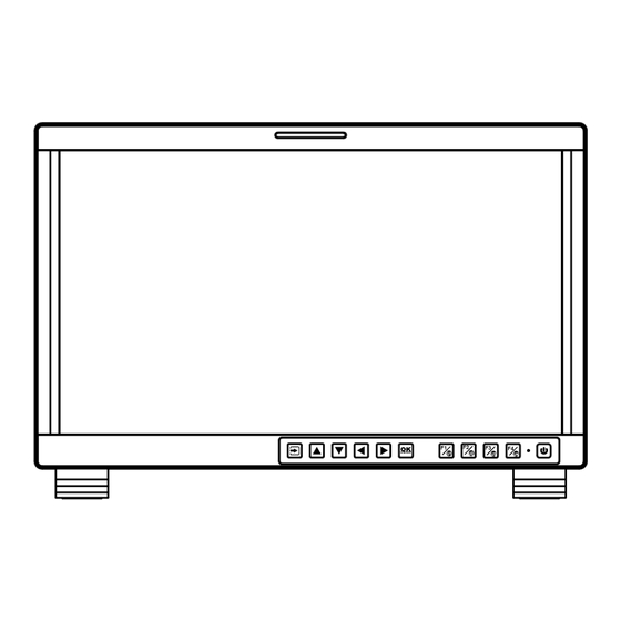
Page 5: Installation Dimensions
2. Installation Dimension Front Panel Side View Rear Panel Top View... -
Page 6: Installation Instructions Of Accessories
3. Installation instructions of accessories Desktop Stand Feet... - Page 7 Sun hood Protective Glass...
- Page 8 C-Stand...
- Page 9 Hanger It provides an inch screw thread hanger as an optional accessory. The hanger provides two sorts of screw thread: 3/8 inch screw thread, a total of 4; 1/4 inch screw thread, a total of 8.
-
Page 10: Operation Instructions
4. Operation Instructions BUTTON FUNCTION BUTTON FUNCTION Input selection Function button F1 Adjust upward Function button F2 Adjust downward Function button F3 Return/Exit Function button F4 Select next Power on/off Save/Return/Main menu All of these buttons have light indicators. 4.1 Operation of Front Panel The functionality and usage of the buttons at the front panel are as follows: Input Selection... - Page 11 toggle among these input signal items. Figure 1 Source Menu UP ARROW It is UP button when working with the main menu. Toggle this button to select the next item or increase the number. Without the Main menu: when not displaying the Main menu, press LEFT button to display the Fast Menu list, as shown in Figure 2, toggle among these menu items: Volume, Brightness, Contrast, Saturation, Backlight and Sharpness.
- Page 12 DOWN ARROW It is DOWN button when working with the main menu. Toggle this button to select the next item or decrease the number. Without the Main menu: when not displaying the Main menu, press DOWN button to display the Fast Menu list, refer to the details in the above description as in UP arrow button.
- Page 13 Save/Back: confirm the selection and back to the higher level menu. Turn Page: when the current selection in the sub-menu list is Next Page, press this button to turn to the next page circularly. F1/U1 This button is a FUNCTION and User Preset button. ...
- Page 14 Arrangement of Rear Panel For the arrangement of the rear panel of FM-17 is shown in Figure 4.2-1, there are various input and output interfaces at the rear panel, and build-in speakers in the top. Figure 4.2-2 The Rear Panel of FM-17 Monitor The interfaces numbered in red are described as follows: 1.
- Page 15 Operations of Rear Panel The details of these interfaces at the rear panel are described as follows: Power Switch It provides one power switch to switch on or switch off. As shown in Figure 4.2-2, push the button to the direction “-” to switch on the power, or push the button to the direction “O”...
- Page 16 HDMI Input: HDMI IN It provides one HDMI input interface, HDMI Type-A connector with a fastener. Audio Output(3.5mm jack): it provides one headphone. Audio Input(3.5mm jack): AUD IN, it provides one audio input interface. USB: it is used for LUT input and firmware upgrading. RS485 Interface (RJ-45) It provides two RS485 interfaces, loop out.
- Page 17 Signal HDMI VIDEO 720P24/23.98 720P25 720P30/29.97 720P50 720P60/59.94 1080SF24/23.98 1080SF25 1080SF29.97 1080SF30 1035I60/59.94 1080I50 1080I60/59.94 1080P24/23.98 1080P25 ...
- Page 18 Signal HDMI VIDEO 1080P60/59.94...
-
Page 19: Functionality Of The Main Menu
5. Functionality of the Main Menu This chapter describes the structure and functionality of the main menu, and introduces how to modify and customize the menu settings. The main menu includes the following menu items, as shown in Figure5-1. Figure 5-1 Main Menu Main Menu Press the OK/MENU button at the bottom of the front panel, the main menu is displayed at the center of the screen, as shown in Figure 5.1-1:... - Page 20 The menu interface is divided into three parts: Main Menu List It contains the menu list of the Main menu. Press UP or DOWN to access the corresponding menu item. Sub-menu list Press right arrow button to enter into the next level of menu list, as shown in Figure 5.1-2, it lists the title of the Sub-menu, the sub-menu item and the value of the item.
- Page 21 The following will introduce the contents and functionality of these sub-menu items in sorts. STATUS Menu The STATUS menu items are used to describe the current status information of the monitor, the menu items are as shown in Figure 5.1-3: Figure 5.1-3 STATUS Menu There are two pages in STATUS menu.
- Page 22 Items Default Value Description Model Show the production model. Serial Number Show the serial number. Firmware Version Show the firmware number. The sub-menu values in STATUS menu can’t be modified, they are displayed the actual status of the monitor. INPUT CONFIG Menu The INPUT CONFIG menu items are used to set the source of the input signals, the menu items are as shown in Figure 5.1-4:...
- Page 23 Default Items Domain Range Description Value VIDEO ON/OFF Enable/Disable VIDEO input HDMI ON/OFF Enable/Disable HDMI input Set the NTSC phase level, and NTSC Phase -50~50 this item is available only when NTSC format signal is input. Signal Format Auto As shown in Table 5.1-3 signal format for the inputs ...
- Page 24 Figure 5.1-5 COLOR MANAGEMENT Menu There are two pages in COLOR MANAGEMENT menu. The relationship of Items, Default Value, Domain Range and Description of the sub-item is shown in Table 5.1-4: Table 5.1-4 The Description of COLOR MANAGEMENT Menu Items Default Items Domain Range...
- Page 25 Default Items Domain Range Description Value Camera SDR Camera Camera Set a LUT from the corresponding Camera HDR Type list User Camera SDR Refer to Table 5.1-5 Load the selected SDR LUT Camera HDR Refer to Table 5.1-5 Load the selected HDR LUT User User1...
- Page 26 Camera LUT LUT Name Company RED_L3G10RWG_Rec709_ R2_V1.13 RED_L3G10RWG_Rec709_ R3_V1.13 RED_L3G10RWG_Rec709_ R4_V1.13 RED_RedLogFilm_RG3 Sony_SLog2SGamut_LCRec709 Sony_SLog2SGamut_LCRec709A Sony Sony_SLog3SG3Cine_LCRec709 Sony_SLog3SG3Cine_LCRec709A ARRI_LogC_HLG_Rec2020 ARRI_LogC_PQ_Rec2020 Canon_Clog2Cin_HLG_Rec2020 Canon_Clog2Cin_PQ_Rec2020 Canon_Clog3Cin_HLG_Rec2020 Canon_Clog3Cin_PQ_Rec2020 Panasonic_VLog_HLG_Rec2020 SWIT Panasonic_VLog_PQ_Rec2020 RED_L3G10_HLG_Rec2020 RED_L3G10_PQ_Rec2020 Sony_SLog3_Cin_HLG_Rec2020 Sony_SLog3_Cin_PQ_Rec2020 Sony_SLog3_SG3_HLG_Rec2020 Sony_SLog3_SG3_PQ_Rec2020 When setting Camera LUT Type item as Camera SDR, Camera HDR or User, the following corresponding Camera SDR, Camera HDR, User item will be activated, and the available ranges of Gamma are diverse, as shown in the following table: Camera LUT Type...
- Page 27 selection, and it will pop up a USER file selection window, press the arrow button to choose from User1~ User16 to set the storage path for the selected LUT. For example, select User1, and press OK/MENU button to confirm the setting. Figure 5.1-6 USB LUT Files Second, power off the device, and restart it to affect the settings above.
- Page 28 Figure 5.1-7 CONFIG Menu There are six pages in USER CONFIG menu. The relationship of Items, Default Value, Domain Range and Description of the sub-item is shown in Table 5.1-6: Table 5.1-6 The Description of USER CONFIG Menu Items Default Items Domain Range Description...
- Page 29 Default Items Domain Range Description Value signal EXT: external signal OFF: no signal When the audio source is Left speaker, select Speak Out L EBD CH1 EBD, the range of this item channel according to the is EBD CH1~ EBD CH16. type of audio source.
- Page 30 Default Items Domain Range Description Value according to the aspect ratio and scan mode. OFF: the safety marker is based on the current input source Whether to set connection ON: the safety Marker Fit between Aspect MARKER and Safety Marker.
- Page 31 Default Items Domain Range Description Value Middle: Right Down/Center Down/Left Down Small: Center Down Enable/Disable Vectorscope OFF/ON vectorscope display Left Up Center Up Right Up Right Center Vectorscope Set the location of the TOP RIGHT ...
- Page 32 Default Items Domain Range Description Value Level value between the edges in an image, and take this value as the reference value. Larger value means more detail detection. Enable/Disable peak Peak ON/OFF function. Over sharpen the image. Set the sharpness level of the image.
- Page 33 Default Items Domain Range Description Value Set whether to restore the Monitor Reset factory settings Firmware Upgrade the firmware Upgrade FUNCTION KEY and User Preset Menu 1. User Preset The user preset provides a series of menu settings customized as a User Preset, up to 4 presets could be defined in this device.
- Page 34 Default Items Range Description Value Enable/Disable false color False Color OFF/ ON function OFF/Mono/ Enable/Disable Focus Assist Focus Assist Focus Assist Color function and set its mode Peak OFF/ON Enable/Disable Peak Zebra OFF/ON Enable/Disable Zebra 2. ASPECT Set the aspect ratio of the screen, it is different from the formats of the input signals, and the details are as shown in Table 5.1-8: Table 5.1-8 The Relationship of Input Signal Formats and Its Aspects Input...
- Page 35 AUDIO Menu The AUDIO menu items are displayed on Page2 in USER CONFIG menu, and they are used to adjust the audio parameters: Figure 5.1-8 CONFIG Menu-Page2 The appearance of Meter is as shown in Figure 5.1-9: Figure 5.1-9 Audio Meter Audio Meter Display Mode Meter Select controls the amount of channels displayed in an audio meter, and each group(G*) contains four channels.
- Page 36 over level line will display red. Figure 5.1-10 The Position of the Audio Meter On Screen Audio Meter Display Position The position of Meter is controlled by Meter Position item, the position of the meter on the screen is as follows: Left, Right. For example, the illustrations of the positions are as shown in Figure 5.1-11: Figure 5.1-11 the Positions of Meter ...
- Page 37 Figure 5.1-12 USER CONFIG Menu-Page3 Markers Marker Illustration Description This marker enables easier checking the center portion’s focus. Center Marker This marker displays two lines to identify an area with a specified ratio. Aspect Marker This marker displays rectangle to identify the safety area with specified...
- Page 38 MARKER MAT The marker mat marks the outside area of the marker display with the appointed transparency. For example, set ASPECT as 16:9, Aspect Marker as 4:3, and Area Marker as 95%, then, the comparison of the three Marker Mats are as shown in Figure 5.1-13: Figure 5.1-13 MARKER MAT MARKER FIT The USER CONFIG ...
- Page 39 DISPLAY Menu The DISPLAY menu items are displayed on Page4 in USER CONFIG menu, and they are used to adjust the parameters displayed on the screen, the menu items are as shown in Figure 5.1-15: Figure 5.1-15 USER CONFIG Menu-Page4 Display Location Set the location of waveform, vectorscope and histogram by USER CONFIG ...
- Page 40 Set various waveform through USER CONFIG Waveform Type item, and display the following three kinds of waveform as LUMA, RGB, PARADE, shown in Figure 5.1-17: Figure 5.1-17 LUMA Waveform and RGB Waveform and PARADE Waveform Waveform Size Set USER CONFIG Waveform SIZE item to adjust the size of the waveform, there are three kinds of sizes for waveform: ...
- Page 41 Histogram Histogram assists in judging the distribution of luminance in the image. Histogram Type Set USER CONFIG HISTOGRAM item to open or close the histogram display, and set the histogram display mode as LUMA or RGB, the two histogram types are as shown in Figure 5.1-19: Figure 5.1-19 RGB Histogram and LUMA Histogram Focus and Exposure Menu...
- Page 42 edge to help camera focus operation. Set USER CONFIG Focus Assist item to enable the focus assist function. The intensified edges are those areas whose difference value exceeds the reference focus level (SENSITIVITY), and the intensified edge are displayed in the designated color set by Focus Assist Color.
- Page 43 Choose the False Color tool to activate the FALSE COLOR function. It provides multiple types of FALSE COLOR types: Spectrum, SONY Slog3, SONY Slog2, ARRI LogC, Canon Clog2, Canon Clog3, Panasonic Vlog, RED RedLogFilm, RED RL3G10, BMD, BMD 4K, ARRI Rec709, SONY LC709A, SONY LC709, Panasonic V709, RED G3, RED G4.
- Page 44 Figure 5.1-25 USER CONFIG Menu-Page7 Display Test Pattern Set USER CONFIG Internal Signal item as ON, it will display the color test pattern on the screen. Set Menu Show Time Set USER CONFIGOsd Time as 10s, 30s or 60s. After you have loaded the menu, it will be closed automatically if you do nothing operation within the OSD Time.
- Page 45 Display Status Menu Set USER CONFIGStatus Display item as ON, the status menu will be displayed in the top left corner of the screen, and it includes the input channel and signal format. Switch Menu Language Set USER CONFIGLanguage item as Chinese or English, and the default menu language is English.
- Page 46 Press right arrow( ) button to select OK command, and click OK/MENU button to confirm the selection, it will read the new firmware files from your USB drive and update your firmware. Make sure you have inserted your USB disk with the stored firmware files into the USB interface of the monitor, or it will inform you a “Can’t Detect USB”...
- Page 47 Figure 5.1-30 IMD Menu The relationship of Items, Default Value, Domain Range and Description of the sub-item is shown in Table 5.1-9: Table 5.1-9 The Description of IMD Menu Items Items Default Value Domain Range Description Set whether to display IMD IMD Display OFF/ON Characters on screen.
- Page 48 corresponding protocol. KEY INHIBIT Menu The KEY INHIBIT menu item is used to lock the setting so that they can’t be changed by an unauthorized user, and the menu item is as shown in Figure 5.1-31: Figure 5.1-31 KEY INHIBIT Menu The relationship of Items, Default Value, Domain Range and Description of the sub-item is shown in Table 5.1-10: Table 5.1-10 The Description of KEY INHIBIT Menu Items...
- Page 49 Menu Settings When checking or modifying the value of the menu item, cooperating with the following buttons: (LEFT), (DOWN), (UP), (RIGHT), OK/MENU. Operations to the Main menu Display the Main Menu Press OK/MENU button to enter into the main menu, it displays at the center of the screen.
- Page 50 the Next Page item. Operations to sub-menu item value Switch sub-menu item value When the control icon is in sub-menu item value, press DOWN or UP button to switch among its value list. Confirm the modification to sub-menu item value Press OK/MENU button to confirm the selection of a value, and the control icon is back to the corresponding sub-menu item.
-
Page 51: Specification
6. Specifications Specification Values Dimension 17.3” Dimension(WxHxD) 421.8x264.3x 48.7mm Pixel Pitch (WxH) 0.1989×0.1989mm Aspect Ratio 16:9 Display Area (WxH) 381.89×214.81mm Viewing Angle (HxV) 178°x178° Color Depth 262K colors Resolution 1920×1080 Contrast (Typ.) 700:1 Luminance (cd/㎡) Response Time (ms) Backlight WhiteLED Backlight Life(Hrs) 15000(Min.) Work Temperature... - Page 52 Specification Values Connector BNC per IEC 169-8 Impedance 75© >18 dB 5 to 270 MHz Return Loss >15 dB 270 MHz to 1.5 GHz >10 dB up to 3 GHz Maximum Signal Level 800 mV pk-pk 10% Signal Amplitude 800 mV pk-pk 10% DC Offset 0 V ±0.5 V Overshoot...
Need help?
Do you have a question about the FM-17 and is the answer not in the manual?
Questions and answers