Table of Contents
Advertisement
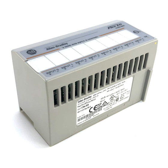
24V dc FLEX I/O
RTD Input Module
(Cat. No. 1794-IR8)
4
Module Installation
This module mounts on a 1794 terminal base unit.
1. Rotate keyswitch (1) on terminal base unit (2) clockwise to position
as required for this type of module.
2. Make certain the flexbus connector (3) is pushed all the way to the left
to connect with the neighboring terminal base/adapter. You cannot
install the module unless the connector is fully extended.
3. Make sure that the pins on the bottom of the module are straight so
they will align properly with the connector in the terminal base unit.
4. Position the module (4) with its alignment bar (5) aligned with the
groove (6) on the terminal base.
5. Press firmly and evenly to seat the module in the terminal base unit.
The module is seated when the latching mechanism (7) is locked into
the module.
FLEX I/O is a trademark of Rockwell Automation
Installation Instructions
3
Allen-Bra
7
1
2
6
5
Publication 1794 5.22 - May 1999
3
Advertisement
Table of Contents

Related Manuals for Allen-Bradley FLEX I/O 1794-IR8


Summary of Contents for Allen-Bradley FLEX I/O 1794-IR8
- Page 1 Installation Instructions 24V dc FLEX I/O RTD Input Module (Cat. No. 1794-IR8) Module Installation This module mounts on a 1794 terminal base unit. 1. Rotate keyswitch (1) on terminal base unit (2) clockwise to position as required for this type of module. 2.
- Page 2 EN 61131–2 Programmable Controllers, Part 2 – Equipment Requirements and Tests. For specific information required by EN 61131-2, see the appropriate sections in this publication, as well as the following Allen-Bradley publications: Industrial Automation Wiring and Grounding Guidelines For Noise Immunity, publication 1770-4.1...
- Page 3 24V dc FLEX I/O RTD Input Module 3 Wiring 1. Connect the individual high and low signal wiring to numbered terminals on the 0–15 row (A) on the terminal base unit as indicated in the wiring table. 2. Connect 24V dc common to terminal 16 on row (B). ATTENTION: You must power this module from the same power supply that supplies the adapter module so they both power up or down together.
- Page 4 24V dc FLEX I/O RTD Input Module 8. Connect the shield to functional earth ground as near as possible to the module. ATTENTION: Total current draw through the terminal base unit is limited to 10A. Separate power connections to the terminal base unit may be necessary. 8 9 10 11 12 13 14 15 0 -15 16-33...
- Page 5 24V dc FLEX I/O RTD Input Module 5 1794 TB3T and TB3TS Terminal Base Units High Signal Low Signal Signal Shield Channel Terminal Terminal Return Return 24V dc Common 16, 17, 19, 21, 23, 25, 27, 29, 31 and 33 +24V dc power 34 and 51 Terminals 39 to 46 are chassis ground.
- Page 6 24V dc FLEX I/O RTD Input Module Example of 2 , 3 and 4 wire RTD Wiring to a 1794 TB3T Base Unit 1 2 3 4 5 6 7 8 9 10 11 12 13 14 15 0 -15 18 19 25 26 16-33...
- Page 7 24V dc FLEX I/O RTD Input Module 7 Block Transfer Read and Write The following block transfer read and write word bit information is presented for experienced users only. Refer to the user manual publication 1794-6.5.4 for this product for complete information on programming and configuring your module.
- Page 8 24V dc FLEX I/O RTD Input Module Data Type Word Description Module Data Type Write word Bits C (default) Bipolar counts scaled between -32768 and +32767 Unipolar counts scaled between 0 and 65535 RTD Type Word Description RTD Type - Range Channel 0 Write Word 1 Resistance (default)
- Page 9 24V dc FLEX I/O RTD Input Module 9 RTD Type - Range Channel 1 - see bits 00-03, word 1 Write Word 1 (continued) (continued) Channel 2 - see bits 00-03, word 1 Channel 3 - see bits 00-03, word 1 Channel 4 - see bits 00-03, word 1 Write Word 2 Channel 5 - see bits 00-03, word 1...
- Page 10 24V dc FLEX I/O RTD Input Module CSA Hazardous Location Approval CSA certifies products for general use as well as for use in hazardous locations. Actual CSA certification is indicated by the product label as shown below, and not by statements in any user documentation.
- Page 11 24V dc FLEX I/O RTD Input Module 11 CSA Hazardous Location Approval ATTENTION: Explosion hazard Substitution of components may impair suitability for Class I, Division 2. Do not replace components unless power has been switched off or the area is known to be non hazardous. Do not disconnect equipment unless power has been switched off or the area is known to be non hazardous.
- Page 12 24V dc FLEX I/O RTD Input Module CSA Hazardous Location Approval Approbation d'utilisation dans des emplacements dangereux par la CSA Taux du code de température Le taux du code de température est indiqué ici Les avertissements suivants s'appliquent aux produits ayant la certification CSA pour leur utilisation dans des emplacements dangereux.
- Page 13 24V dc FLEX I/O RTD Input Module 13 Specifications - 1794 IR8 RTD Input Module Number of Inputs 8 Channels Module Location Cat. No. 1794 TB3, TB3S, TB3T, and TB3TS Terminal Base Units Signal Input Range 1 to 433 ohms Sensors Supported Resistance: 100 ohm Pt α...
- Page 14 24V dc FLEX I/O RTD Input Module Specifications - 1794 IR8 RTD Input Module RFI Immunity Error of less than 1% of range at 10V/M 27 to 1000MHz Input Offset Drift with Temperature 1.5 milliohm/ C maximum Gain Drift with Temperature Normal mode: 20 ppm/ C maximum...
- Page 15 24V dc FLEX I/O RTD Input Module 15 Specifications - 1794 IR8 RTD Input Module Agency Certification CSA certified (when product is marked) CSA Class I, Division 2 Groups A, B, C, D certified UL listed CE marked for all applicable directives User Manual Publication 1794 6.5.4 Derating Curve...
- Page 16 24V dc FLEX I/O RTD Input Module User Manuals Thank you for purchasing this product. This product has a user manual associated with it. If you would like a manual, you can: download a free electronic version from the internet:: www.ab.com/manuals or www.theautomationbookstore.com purchase a printed manual by:...
Need help?
Do you have a question about the FLEX I/O 1794-IR8 and is the answer not in the manual?
Questions and answers