
Related Manuals for Azkoyen Tempo MI


Summary of Contents for Azkoyen Tempo MI
- Page 1 Technical information T E M P O Avda. San Silvestre, s/n 31350 Peralta (Navarra) Spain Tel.: +34 948 709 709 www.sat.azkoyen.com...
- Page 2 I N D E X INTRODUCTION 1.1. DEFINITIONS 1.2. RANGE 1.3. PRINCIPLE TECHNICAL CHARACTERISTICS DESCRIPTION OF COMPONENTS 2.1. PRINCIPLE COMPONENTS 2.2. HYDRAULIC CIRCUIT FOR ESPRESSO COFFEE 2.3. HYDRAULIC CIRCUIT FOR INSTANT PRODUCTS INSTALLATION AND SWITCHING ON 3.1. UNPACKING 3.2. SWITCHING ON 3.3.
- Page 3 INTRODUCTION The automatic vending machines in the TEMPO range are destined to the elaboration and sale of espresso coffee and instant beverages that consist of the mixture of hot water and soluble powder or granules. The product is served in a plastic cup. In the rest of this document the following elements will be called: TEMPO The machines in the...
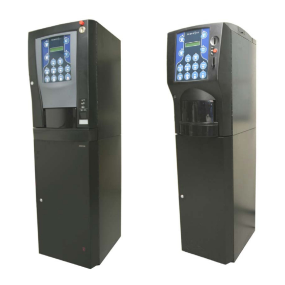
- Page 4 1.2. RANGE The TEMPO range is comprised of the M, Mz, L and Lz series. The cabinets of the Mz and Lz series are narrower than those in the M and L series. Each of the four series have models that elaborate espresso coffee and instant products.
- Page 5 Power supply: TEMPO instant Voltage Power Length Mains voltage 230 Vac / 50 Hz Heating element 230 Vac / 50 Hz 1500 W Average daily consumption 3500 W Mains flex 3700 mm TEMPO espresso Voltage Power Length Mains voltage 230 Vac / 50 Hz Heating element 230 Vac / 50 Hz 1500 W Average daily consumption...
- Page 6 DESCRIPTION OF COMPONENTS 2.2. PRINCIPLE COMPONENTS A1 A2 A3 A4 A5 A6 A7 A8 A9 Residue liquid bucket It collects all the residue liquids that the machine generates. It has a capacity of 8 litres. When it reaches a determined level a float device is activated to put the machine out of order until it is emptied.
- Page 7 Infusion element Made of resin, it is the element that the machine uses to make the espresso coffee. Between the piston and its support there is a spring and a espacer that, depending how it is placed, will vary the capacity of ground coffee the chamber will hold. The spacer should be placed between the piston and its support when the dosage is set for 5 to 6.5 g of ground coffee.
- Page 8 The possible regulation of the capacity of the infusion element, using the washer, and the position of the dosage handle are shown in the table below: Dose Piston washer position Dosage position Under Under 5.5 g Under Under 6.5 g Over Over 7.5 g...
- Page 9 C1. Piston C2. Spring C3. Washers C4. Infusion element C5. Lever C6. Holding handle C7. Extraction button C8. Position micro switch C9. Presence micro switch C10. Infusion element movement handle C11. Filter Beaters The mixing of the products with hot water from the boiler is done with these elements. Technical characteristics: Make of motor Mabuchi...
- Page 10 The EVs are positioned horizontally and correspond to the following products: Tempo ME D1. Decaffeinated D2. Coffee D3. Milk y chocolate Tempo MI D1. Coffee and decaffeinated D2. Milk D3. Chocolate Tempo LE D1. Descafeinado D2. Milk and chocolate D3. Coffee D4.
- Page 11 Technical characteristics: Voltage 24 Vdc Regulation Minimum 5g and maximum 8g Regulation lever 7 points: Point 1 is 5 g Point 7 is 8 g E1. Micro switch E2. Solenoid E3. Micro activated flap E4. Regulation lever Coffee bean hopper The capacity is: Series ME 1.3 kg...
- Page 12 Programming box This element is used for programming the machine. Extractor systems for cups, sugar and spoons The three systems are mounted in the one support. The MI and LI series, standard, do not have a container for spoons To remove the extractors from the machine, follow these steps: Disconnect the wiring loom from the cup extractor board.
- Page 13 F1. Clip F2. Sugar and spoon extractor motor F3. Cup extractor motor F4. Cup container movement motor F5. Cup support arm F6. Cup arm motor F7. Control board F8. Cup extraction button F9. Cup presence photocells F10. Hopper position micro F11.
- Page 14 • The cup container is divided into 5 separate columns. When one of them runs out of cups, the motor turns the container until the next column is situated over the extractor. After the motor turns for 6.5 seconds and the photocells do not detect a new column of cups, the machine will go out of order and the display will show “Out of cups”.
- Page 15 A10. Product extractors Technical characteristics: Motor manufacturer Mabuchi Voltage 24 Vdc Speed 40 rpm A11. Coin system All the models in the TEMPO L range use coin changers with Executive or MDB communication protocol. The models in the TEMPO M range use a coin validator. It is always “exact amount”; no change given.
- Page 16 G1. Conector for MDB communication protocol coin system G2. Conectors for communication executive protocol coin system A12. Coffee grinder It has the model M03 from Azkoyen installed, although before they had the grinder from Componenti installed Componenti 1ª 10012 - E...
- Page 17 Technical characteristics: Componenti Voltage 230 Vca 230 Vca Nominal power 65 w 350 w Speed 1.250 rpm 1390 rpm Diameter of the grinders 45 mm 63 mm Grind points 0,026 mm 0,026 mm Moving the handle anticlockwise gives a coarser grind and moving it clockwise gives a finer grind.
- Page 18 A14. Product door Made of polycarbonate, its main purpose is to prevent the entry of insects into the machine. It can be removed by removing the holding plate on the interior of the machine. A15. Water inlet EV It allows the entry of water from the mains to the cold water deposit. It works at 230 Vac. This EV is only fitted to machines that are connected to the mains water supply.
- Page 19 K1. By-pass K2. Anti return valve When an espresso coffee is elaborated, the water pressure needed is quite high to be able to pass through the compressed ground coffee in the infusion element. This resistance the coffee offers makes the water pressure in the boiler increase up to a pressure of 9 Kg/cm². At this pressure the by-pass (2) opens allowing a small amount of water to return;...
- Page 20 A18. Cold water deposit Made of polypropylene, It has the capacity of 500 cc. It is at atmospheric pressure and temperature. From this deposit is taken the water to elaborate the espresso coffee and instant beverages. The water level in the deposit is controlled by a float that activates a magnetic switch. A19.
- Page 21 M1. Solenoid M2. Valve M3. 3º outlet When the machine is in the espresso coffee making process, the third is closed while the outlet from the boiler and the inlet to the infusion element are open to each other. N1. 3 closed N2.
- Page 22 Technical characteristics: Heating element voltage 230 Vac Power 1.500 w Temperature programming 40 a 99º C Safety protection with manual reset 120º C Voltage of EVs 24 Vac Power of instant EV Power of espresso coffee 10 w Maximum pressure of EVs 15 Kg./cm²...
- Page 23 ºC 100,00 100,39 100,78 101,17 101,56 101,95 102,34 102,73 103,12 103,51 103,90 104,29 104,68 105,07 105,46 105,85 106,24 106,63 107,02 107,40 107,79 108,18 108,57 108,96 109,35 109,73 110,12 110,51 110,90 111,28 111,67 112,06 112,45 112,83 113,22 113,61 113,99 114,38 114,77 115,15 115,54 115,93 116,31 116,70 117,08 117,47 117,85 118,24 118,62 119,01 119,40 119,78 120,16 120,55 120,93 121,32 121,70 122,09 122,47 122,86 123,24 123,62 124,01 124,39 124,77 125,16 125,54 125,92 126,31 126,69...
- Page 24 A20. Extractor The steam and vapour that is generated by the beaters can reach the product containers and if they become damp they form lumps in the powder. This consequently results in the irregular extraction of the product. To avoid this, the extractor is used to remove the steam and vapour from the interior of the machine.
- Page 25 Black 220Vac Black Blue 24Vac Blue R1. Main module R2. Payment module R3. infusion module R4. IDU module R5. Cup module The five boards are joined by one loom of 6 strands called a CAN bus. Two of these wires are used for the transmission of 34 volts, another two for 8 volts and the remaining two are used for the communication between boards.
- Page 26 2.2. HYDRAULIC CIRCUIT OF THE ESPRESSO COFFEE In the following diagram are represented all the elements of the machine that are needed to control and make the water reach the infusion element or the instant beverage beaters. S1. Water inlet S2.
- Page 27 method the infusion reaches the cup from a lesser height than the height of the outlet tube of the infusion group, and thus avoiding bubbles in the tea. T1. Container for green tea (Infusion) T2. Instant tea beater Electro-valve outlet 1ª...
- Page 28 INSTALLATION AND SWITCHING ON 3.1. UNPACKING The power supply of the machine requires a socket, or another system, that allows its disconnection. The method used must guarantee the complete disconnection of both poles. Elemental safety requirements: a) Never touch any mechanisms with wet hands or feet. b) Never connect or use the machine barefoot.
- Page 29 3.2.3. Connecting a Coin Validator (Ranges MI/ME) The Tempo ME and Tempo MI models are factory prepared to install a coin validator, which can be from Azkoyen or another manufacturer. The validator is not supplied with the machine. The fitting of the validator is simple; it is clipped into the bracket.
- Page 30 3.2.4. Installing the coin changer with Executive or MDB protocol The Tempo LE and Tempo LI models admiten cualquier monedero con protocolo MDB o Ejecutivo. Se fija mediante tres tornillos al soporte situado en la puerta. Este soporte es el mismo para los dos modelos de monedero.
- Page 31 W1. Coffee bean hopper W2. Instant powder hoppers Now the machine can be switched on. 3.2.6. Filling the hot water boiler On connecting the machine the hot water boiler fills automatically. In the espresso coffee machines the following process occur: The cold water deposit fills up, if it is empty.
- Page 32 3.3. ERROR MESSAGES SHOWN ON THE DISPLAY The description of the incident, the corresponding message that the display shows and the codes that in each case will be transmitted when using VTM or EVADTS communication protocols are: Notes: ► The machine is “out of order” number of the element that is faulty Description Message on the Display...
- Page 33 Fault detector product (fault type 2) FAULT IDETECT Switch on of the machine OEZN Switch off of the machine OEZF Activation of infra red reception OEZI Communication AZKOYEN protocol OEZA Communication EVADTS protocol OEZE Communication VTM under SMS OEZS Reset configuration Machine NOT CFG[F401] ECZC ►...
- Page 34 Description Message on the Display EVADTS Gate undefined position, both micros closed DEL. DOOR P.D. MC Gate undefined position, both micros closed DEL. DOOR P.D. MA Detected manipulation of collection hatch DEL. DOOR MANIP. Product collection hatch open Received module software by EVADTS Received module software by MDB Fault in system heater ERROR CALDERA...
- Page 35 3.4. Control points Heating element It is measured on the infusion board on the connector Between pins 1 and 2 (black and brown) it will show 0 Vac when the heating element is working. (Keeping in mind the 10 Amp fuse is correct) Between pins 1 and 2 it will show 220 Vac when the heating element is not heating.
- Page 36 Volume counter It is measured on the infusion board on the connector J10. The pin 3 corresponds to +, the pin 4 to ground and the pin 2 to signal. When the counter spins, the reading will show 2.5 Vdc measuring between pins 2 and 4. Water level buoy It is measured on the infusion board on the connector J10.
- Page 37 Between pins 9 and 11 it will show 25 Vdc when the motor is working. Motor for turning the cup container It is measured on the Cup Board on the connector J5. Between pins 7 and 10 it will show 30 Vdc when the motor is at rest. Between pins 7 and 10 it will show 0 Vdc when the motor is working.
- Page 38 Temperature probe It is measured on the infusion board on the connector J2. It measures the resistance values (see the table for the PTC values). 4. CLEANING AND MAINTENANCE Daily Liquid residue bucket. Empty the waste water and rinse with clean water. Solid waste bucket.
- Page 39 Depending on the use of the machine Piston filter. Every 15,000 services, it is recommended to remove and clean it. If necessary, it can be cleaned with a non metallic brush. If the holes are blocked, do not introduce sharp objects into the holes to clean them. It is recommended to replace the filter with a new one when is becomes blocked.
- Page 40 Juntas Maintenance tool The maintenance tool is used in machines in the Tempo and City series to carry out various advanced configuration and programming tasks. The tool is micro-processor controlled and has a flash memory with a capacity to store at least 8 programme modules, 100 configurations or a combination of both.
- Page 41 WORKING CONDITIONS AND NORMS The optimum working conditions of this equipment is achieved by fulfilling the following requirements: Temperatures: Storage: -25 to + 70ºC. Working: 0 to 50º C. Maximum relative humidity without condensation 85% Norms that are met: The coffee machines meet the following EU directives: Directive 73/23/CEE electrical safety and Directive 89/336/CEE electromagnetic compatibility.
- Page 42 DIMENSIONS The measurements are in mm and the weights in Kg. M A C H I N E Tempo Width Height Depth Weight ME/MI 1620 49/44 LE/LI 1830 60/55 C A B I N E T Tempo Width Height Depth Weight ME/MI 16/16...
- Page 43 1ª 10012 - E 02 - 2006...
Need help?
Do you have a question about the Tempo MI and is the answer not in the manual?
Questions and answers