
Related Manuals for Lycoming TEO-540-C1A


Summary of Contents for Lycoming TEO-540-C1A
- Page 1 Engine Maintenance Manual Principal Manual) TEO-540-C1A Engine November 2018 Part No. MM-TEO-540-C1A © 2018 Avco Corporation. All Rights Reserved.
- Page 2 Visit us Online: www.lycoming.com NOTE: Lycoming recommends that owners of this manual sign up for email notification on the Technical Publications page of our website https://www.lycoming.com/contact/knowledge-base/publications. By submitting your email address, you will receive notification whenever Lycoming publishes a new...
-
Page 3: Record Of Revisions
TEO-540-C1A Engine Maintenance Manual TEO-540-C1A Engine Maintenance Manual RECORD OF REVISIONS Revision Revision Date Revised By Revision Description Original Original Release of Maintenance Manual - Part No. MM-TEO-540-C1A © 2018 Avco Corporation. All Rights Reserved Record of Revisions November 2018... - Page 4 TEO-540-C1A Engine Maintenance Manual TEO-540-C1A Engine Maintenance Manual This page intentionally left blank. Record of Revisions © 2018 Avco Corporation. All Rights Reserved Page ii November 2018...
-
Page 5: Service Document List
TEO-540-C1A Engine Maintenance Manual TEO-540-C1A Engine Maintenance Manual SERVICE DOCUMENT LIST NOTICE: The following is a list of service documents referenced in or incorporated into the information in this manual. Always refer to the latest revision of any service document (including any supplements) for changes or additional information. - Page 6 11/18 Pre-oil the Engine Prior to Initial Start S.I. 1267 11/18 Piston Pin Plug Usage S.I. 1285 11/18 Non-Destructive Testing of Lycoming Engine Parts S.I. 1301 11/18 Identification of Primer and Fuel Injector Lines S.I. 1304 11/18 Engine Nameplate Replacement S.I.
- Page 7 Counterweight and Roller Removal, Inspection, and Installation S.I. 1562 11/18 Turbocharged Exhaust System Installation S.I. 1566 11/18 Lycoming Engines Approves the Use of Safety Cable S.I. 1573 11/18 Lycoming TEO-540 Engine Series Engine Control Unit (ECU) Assembly Cross-References L114 11/18...
- Page 8 TEO-540-C1A Engine Maintenance Manual TEO-540-C1A Engine Maintenance Manual This page intentionally left blank. Service Document List © 2018 Avco Corporation. All Rights Reserved Page vi November 2018...
-
Page 9: Table Of Contents
25-Hour Engine Inspection for TEO-540-C1A Engines............19 — 50-Hour Engine Inspection for TEO-540-C1A Engines............21 — 100-Hour or Annual Engine Inspection for TEO-540-C1A Engines ........24 — 250-Hour Engine Inspection for TEO-540-C1A Engines ............29 — 400-Hour Engine Inspection for TEO-540-C1A Engines ............ -
Page 10: Table Of Contents
................ 05-50 — Lightning Strike - After a lightning strike ................47 — Engine Overspeed ........................47 — Table 1 - Overspeed Values for TEO-540-C1A Engines ..........48 — Engine Overboost ........................50 — Incorrect Fuel or Fuel Contamination ..................50 —... - Page 11 TEO-540-C1A Engine Maintenance Manual TEO-540-C1A Engine Maintenance Manual Subject Page Servicing - Replenishing ....................12-10 — Refueling ..........................65 — Oil Level Check ........................65 — Oil Consumption ........................66 — Oil Type and Viscosity ......................66 — Add Oil to the Engine ......................
- Page 12 TEO-540-C1A Engine Maintenance Manual TEO-540-C1A Engine Maintenance Manual Subject Page Engine Disassembly....................... 72-05 — Engine Disassembly Procedure ..................... 107 — Table 1 – Sequence of Engine Disassembly Procedure ........... 107 Engine Assembly ......................72-10 — Corrosion Prevention ......................113 —...
- Page 13 TEO-540-C1A Engine Maintenance Manual TEO-540-C1A Engine Maintenance Manual Subject Page Crankcase Maintenance (Cont.) .................. 72-20 — Crankshaft Assembly ......................164 — Piston Cooling Nozzle Installation (if removed) ..............174 — Oil Plug Installation (if removed) ..................174 — Tappet Assembly Installation....................
- Page 14 TEO-540-C1A Engine Maintenance Manual TEO-540-C1A Engine Maintenance Manual Subject Page Cylinder Maintenance (Cont.) ..................72-30 — Cylinder Borescope Inspection ..................... 212 — Table 3 - Borescope Inspection Steps, Results, and Corrective Action ......213 — Exhaust Valve and Guide Inspection ..................
- Page 15 TEO-540-C1A Engine Maintenance Manual TEO-540-C1A Engine Maintenance Manual Subject Page Lubrication System Maintenance (Cont.) ..............72-50 — Oil Filler Extension and Oil Level Gage Assembly Installation .......... 261 — Oil Pressure Relief Valve Removal ..................261 — Oil Pressure Relief Valve Inspection ..................
- Page 16 TEO-540-C1A Engine Maintenance Manual TEO-540-C1A Engine Maintenance Manual Subject Page Electrical System Maintenance (Cont.) ............... 72-70 — ECU Removal ........................298 — ECU Installation ........................298 — Power Box Removal ......................299 — Power Box Installation ......................299 — Permanent Magnet Alternator (PMA) Replacement .............
- Page 17 TEO-540-C1A Engine Maintenance Manual TEO-540-C1A Engine Maintenance Manual Subject Page Engine Fuel and Control - Controlling ............... 73-20 — (Electronic) Throttle Body Replacement ................329 — Operational Test of Throttle Body ..................330 Ignition System Maintenance ..................74-20 — Ignition Lead Removal......................
- Page 18 ......................373 — ECU to FST Connection ......................381 — Access the Field Service Tool ....................383 — Sending Data to Lycoming Technical Support ..............391 — Field Service Tool - Software Problems ................393 Appendix D ........................— Troubleshooting Guide Abbreviations and Acronyms ............
-
Page 19: Abbreviations And Acronyms
TEO-540-C1A Engine Maintenance Manual TEO-540-C1A Engine Maintenance Manual ABBREVIATIONS AND ACRONYMS Data Logger Airframe Manufacturer’s Manual Air Transportation Association Celsius Camshaft Speed Sensor Cylinder Head Temperature CIP-P Primary Compressor Inlet Pressure CIP-S Secondary Compressor Inlet Pressure Centimeter CRANK Crankshaft Speed Sensor... - Page 20 TEO-540-C1A Engine Maintenance Manual TEO-540-C1A Engine Maintenance Manual ABBREVIATIONS AND ACRONYMS (CONT.) Instructions for Continued Airworthiness Identification; Inside/Inner Diameter in.-lb. Inch Pound (torque) Inch, inches In-Hg Inches of Mercury Engine Installation and Operation Manual KNOCK Knock Sensor Kilopascal Liter Pound...
- Page 21 TEO-540-C1A Engine Maintenance Manual TEO-540-C1A Engine Maintenance Manual ABBREVIATIONS AND ACRONYMS (CONT.) Revolutions per Minute Special Advisory Society of Automotive Engineers (oil viscosity) Service Bulletin Service Instruction Supplemental Type Certificate Time Between Overhaul Top Dead Center Total Indicator Reading Turbine Inlet Temperature Sensor...
- Page 22 TEO-540-C1A Engine Maintenance Manual TEO-540-C1A Engine Maintenance Manual This page intentionally left blank. Abbreviations and Acronyms © 2018 Avco Corporation. All Rights Reserved Page xx November 2018...
-
Page 23: Introduction
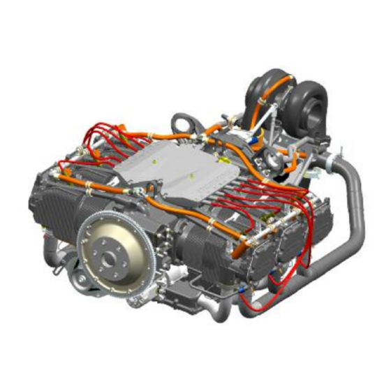
TEO-540-C1A Engine Maintenance Manual INTRODUCTION The Lycoming TEO-540-C1A Engine (Figure 1) is a direct-drive six-cylinder, horizontally opposed, turbocharged, electronically-controlled engine. It has electronic fuel injection, electronic ignition, and down exhaust. As standard equipment, this engine has an automotive type starter, an alternator, and two standard AN type accessory drives. - Page 24 TEO-540-C1A Engine Maintenance Manual TEO-540-C1A Engine Maintenance Manual Engine Serial Number/Engine Data Plate Every engine sent from the factory is identified by a unique serial number. The engine serial number is identified on the engine data plate (Figure 2). Do not remove the engine data plate.
- Page 25 PROCEDURES IN THIS MANUAL MUST BE DONE BY QUALIFIED PERSONNEL WITH THE REQUISITE CERTIFICATIONS. Before you do maintenance on the TEO-540-C1A engine, read this manual in its entirety. Obey all procedures and inspections in this manual. NOTICE: Please read your warranty for a full statement of your rights, limitations and obligations that exist there under.
- Page 26 For additional publication information, look on Lycoming’s website (Lycoming.com) or speak to Lycoming Engines by telephone: U.S. and Canada toll free: +1(800) 258-3279; or Direct: +1 (570) 323-6181. Applicable information from Lycoming Engines' Service Bulletins, Service Instructions, and Service Letters are included in this manual at the time of publication.
- Page 27 TEO-540-C1A Engine Maintenance Manual List of Publications Refer to the latest revision of Service Letter No. L114 for a list of Lycoming Engines' publications. Simplified Technical English The text in the manual is written in the form of Simplified Technical English in compliance with FAA requirements and to make translation into other languages easier.
- Page 28 TEO-540-C1A Engine Maintenance Manual TEO-540-C1A Engine Maintenance Manual This page intentionally left blank. Introduction © 2018 Avco Corporation. All Rights Reserved Page xxvi November 2018...
-
Page 29: Airworthiness Limitations
FAA-approved. 2. Mandatory Inspection - Exhaust Valve and Guide At every 1000 hours of operation for TEO-540-C1A engines, examine the exhaust valve and guide conditions. Refer to the section "Exhaust Valve and Guide Inspection" in Chapter 72-30. - Page 30 TEO-540-C1A Engine Maintenance Manual TEO-540-C1A Engine Maintenance Manual This page intentionally left blank. Airworthiness Limitations © 2018 Avco Corporation. All Rights Reserved Page xxviii November 2018...
-
Page 31: Required Maintenance
(break-in/flight test), fuels and oil to be used, and operating specifications are included in the TEO-540-C1A Engine Installation and Operation Manual. 3. List of Tools for Service and Maintenance Table 1 identifies tools used for service and maintenance. - Page 32 64876 Reamer, 0.015 o/s Counterweight Bushing Holes (for Lug Bushings per S.I. 1142) 64892-2 Circlip Check Gage 64941 Tappet Assembly Tool Field Service Tool Software (Downloadable from www.lycoming.com) 05-00 © 2018 Avco Corporation. All Rights Reserved Page 2 November 2018...
-
Page 33: Time Between Overhaul (Tbo)
Refer to the latest revision of Service Instruction No. SI-1009 for any changes or special circumstances for the recommended TBO. Lycoming Engines recommends engines be sent to the factory for overhaul. 5. Safety Precautions - Before Engine Maintenance WARNING BEFORE THE START OF ANY SERVICE OR MAINTENANCE ON AN... - Page 34 TEO-540-C1A Engine Maintenance Manual TEO-540-C1A Engine Maintenance Manual All safety cable installed on the engine must meet or exceed specifications in the latest revision of AS3510. Safety cable must be installed per the safety cable manufacturer’s instructions and in accordance with specifications in the latest revisions of AS4536 and AS567 and the latest revision of Service Instruction No.
-
Page 35: General Engine Inspection Criteria
• Replace any bent, damaged, or stripped studs, refer to Appendix A 8. Requirements for Engine Maintenance A. These engines must be maintained using Lycoming Engines’ approved methods and procedures. B. Refer to the latest revision of Service Bulletin No. SB-240 for a list of parts that must be replaced whenever they are removed. - Page 36 TEO-540-C1A Engine Maintenance Manual TEO-540-C1A Engine Maintenance Manual This page intentionally left blank. 05-00 © 2018 Avco Corporation. All Rights Reserved Page 6 November 2018...
-
Page 37: Time Limits / Inspections
1000-Hour Engine Inspection Time Between Overhaul (TBO) Refer to the latest revision of Service Instruction No. SI-1009 for any Lycoming Engines recommends engines be sent to the changes or special circumstances for factory for overhaul. the recommended TBO. NOTICE: An operational ground check must be completed prior to and after each inspection and after maintenance. - Page 38 TEO-540-C1A Engine Maintenance Manual TEO-540-C1A Engine Maintenance Manual This page intentionally left blank. 05-10 © 2018 Avco Corporation. All Rights Reserved Page 8 November 2018...
-
Page 39: Required Engine Inspections For Teo-540-C1A Engines
IT CAN CAUSE INJURY. REFER TO THE "VOLCANIC ASH REMOVAL" PROCEDURE IN CHAPTER 05-30. Copy and complete the Visual Inspection Checklist in this chapter for TEO-540-C1A engines each time this inspection is done as a record of engine service. Record the engine hours. - Page 40 TEO-540-C1A Engine Maintenance Manual TEO-540-C1A Engine Maintenance Manual Visual Inspection Checklist for TEO-540-C1A Engines Engine Serial Number:_______________________ Engine Time:_________________________ Date Inspection Done:____________________ Inspection done by:________________________ Findings/ Item Comments Done Corrective Action Engine Compartment Look for and remove unwanted dirt, dust, sand, or particles on the engine and in its compartment.
- Page 41 TEO-540-C1A Engine Maintenance Manual TEO-540-C1A Engine Maintenance Manual Visual Inspection Checklist for TEO-540-C1A Engines (Cont.) Findings/ Item Comments Done Corrective Action Lubrication System Examine the oil pressure relief valve, Refer to Chapters 12-10 oil cooler bypass valve, oil filter and and 72-50.
- Page 42 TEO-540-C1A Engine Maintenance Manual TEO-540-C1A Engine Maintenance Manual Visual Inspection Checklist for TEO-540-C1A Engines (Cont.) Cylinders - Refer to Figures in Chapter 72-30. Item to Examine Cyl. 1 Cyl. 2 Cyl. 3 Cyl. 4 Cyl. 5 Cyl. 6 NOTICE: During the first hours of service, engines can have some leakage at the cylinder base or the cylinder base studs.
- Page 43 TEO-540-C1A Engine Maintenance Manual TEO-540-C1A Engine Maintenance Manual Visual Inspection Checklist for TEO-540-C1A Engines (Cont.) Findings/ Item Comments Done Corrective Action Crankcase Examine the external surface of the crankcase for damage and cracks per the “Exterior Crankcase Inspection” in Chapter 72-20.
- Page 44 TEO-540-C1A Engine Maintenance Manual TEO-540-C1A Engine Maintenance Manual Visual Inspection Checklist for TEO-540-C1A Engines (Cont.) Findings/ Item Comments Done Corrective Action Wiring Harness (Cont.) Examine electrical connectors for If corrosion is found, evidence of corrosion. disconnect, examine the connector, and clean or replace the connector as required.
- Page 45 (5) Start the engine and run-up per instructions in the “Engine Initiation” chapter of the TEO- 540-C1A Engine Installation and Operation Manual. (6) Operate the engine for 3 minutes on the ground (per the TEO-540-C1A Engine Installation and Operation Manual.) Complete a leak check while the engine is in operation.
-
Page 46: Operational Leak Check Sheet For Teo-540-C1A Engines
TEO-540-C1A Engine Maintenance Manual TEO-540-C1A Engine Maintenance Manual Operational Leak Check Sheet for TEO-540-C1A Engines Engine Serial Number:_______________________ Engine Time:_________________________ Date Inspection Done:____________________ Inspection done by:________________________ Findings/ Item Comments Done Corrective Action Examine the cowling, engine and Identify and correct the... -
Page 47: 10-Hour Initial Engine Inspection For Teo-540-C1A Engines
3. 10-Hour Initial Engine Inspection for TEO-540-C1A Engines Complete this inspection after the first 10 hours of initial operation of the engine. Copy and complete the 10-Hour Initial Engine Inspection Checklist for TEO-540-C1A engines as a record of engine service. Record the engine hours. - Page 48 TEO-540-C1A Engine Maintenance Manual TEO-540-C1A Engine Maintenance Manual 10-Hour Initial Engine Inspection Checklist for TEO-540-C1A Engines (Cont.) Inspection Item Comments Results/Notes Done Complete the Operational Look for leaks. Identify Ground Check in Chapter 72- and correct the cause of any leak. Correct any...
-
Page 49: 25-Hour Engine Inspection For Teo-540-C1A Engines
• If the rate of oil consumption has not stabilized NOTICE: Refer to the “Oil Servicing Schedule” in Chapter 12-10. C. Copy and complete the 25-hour Engine Inspection Checklist for TEO-540-C1A engines as a record of engine service. Record the engine hours. - Page 50 Correct any problem before flight Ground Check in Chapter 72- to make sure the engine operates correctly to specifications.* *Appendix A of the TEO-540-C1A Engine Installation and Operation Manual. 05-20 © 2018 Avco Corporation. All Rights Reserved Page 20 November 2018...
-
Page 51: 50-Hour Engine Inspection For Teo-540-C1A Engines
B. Complete the 50-Hour Engine Inspection after every 50 hours of engine operation or every 4 months (whichever occurs first). C. Copy and complete the 50-hour Engine Inspection Checklist for TEO-540-C1A Engines as a record of engine service. Record the engine hours. - Page 52 TEO-540-C1A Engine Maintenance Manual TEO-540-C1A Engine Maintenance Manual 50-Hour Engine Inspection Checklist for TEO-540-C1A Engines (Cont.) Inspection Item Comments Results/Notes Done Remove, examine, clean and Refer to the section in install the oil suction screen at Chapter 12-10: "Oil the oil sump. Replace the oil...
- Page 53 TEO-540-C1A Engine Maintenance Manual TEO-540-C1A Engine Maintenance Manual 50-Hour Engine Inspection Checklist for TEO-540-C1A Engines (Cont.) Inspection Item Comments Results/Notes Done Fuel System Complete the “Fuel System Inspection” and checklist in Chapter 73-10. Induction System Refer to the “Induction Complete the Induction System Inspection”...
-
Page 54: 100-Hour Or Annual Engine Inspection For Teo-540-C1A Engines
100 hours of operation or during each annual aircraft inspection (whichever occurs first). C. Copy and complete the 100-hour or Annual Engine Inspection Checklist for TEO-540-C1A engines as a record of engine service. Record the engine hours. - Page 55 TEO-540-C1A Engine Maintenance Manual TEO-540-C1A Engine Maintenance Manual 100-Hour or Annual Engine Inspection Checklist for TEO-540-C1A Engines (Cont.) Inspection Item Comments Results/Notes Done Fuel System Complete the Fuel System Refer to the section "Fuel System Inspection” procedure in Chapter 73- Inspection.
- Page 56 TEO-540-C1A Engine Maintenance Manual TEO-540-C1A Engine Maintenance Manual 100-Hour or Annual Engine Inspection Checklist for TEO-540-C1A Engines (Cont.) Inspection Item Comments Results/Notes Done Ignition System CAUTION NEVER INSTALL A SPARK PLUG THAT HAS BEEN DROPPED ON THE FLOOR. Remove, examine, rotate, clean, Replace worn spark plugs.
- Page 57 TEO-540-C1A Engine Maintenance Manual TEO-540-C1A Engine Maintenance Manual 100-Hour or Annual Engine Inspection Checklist for TEO-540-C1A Engines (Cont.) Inspection Item Comments Results/Notes Done Engine Controls Examine the knock, temperature, If a damaged sensor is found, and pressure sensors for security replace the sensor.
- Page 58 TEO-540-C1A Engine Maintenance Manual TEO-540-C1A Engine Maintenance Manual 100-Hour or Annual Engine Inspection Checklist for TEO-540-C1A Engines (Cont.) Inspection Results/Notes Done Item Cylinder Compression Check Complete the “Cylinder Compression Check Procedure” in Chapter 72-30. Record the results for each cylinder.
-
Page 59: 250-Hour Engine Inspection For Teo-540-C1A Engines
B. The purpose of this inspection is to examine the exhaust system and turbocharger. C. Copy and complete the 250-Hour Engine Inspection Checklist for TEO-540-C1A engines as a record of engine service. Record the engine hours. -
Page 60: 400-Hour Engine Inspection For Teo-540-C1A Engines
B. The purpose of this inspection is to examine the engine cylinders and to complete a cylinder borescope inspection on each cylinder. C. Copy and complete the 400-Hour Engine Inspection Checklist for TEO-540-C1A Engines as a record of engine service. Record the engine hours. - Page 61 TEO-540-C1A Engine Maintenance Manual TEO-540-C1A Engine Maintenance Manual 400-Hour Engine Inspection Checklist for TEO-540-C1A Engines (Cont.) Complete the “Cylinder Borescope Inspection” procedure in Chapter 72-30. Record the results below for each engine cylinder. Cylinder 1 Cylinder 2 Cylinder 3 Cylinder 4...
-
Page 62: 1000-Hour Engine Inspection For Teo-540-C1A Engines
If this 1000-hour inspection is completed prior to the scheduled 1000-hour inspection it must be completed 1000 hours from the time of inspection. C. Copy and complete the 1000-Hour Engine Inspection Checklist for TEO-540-C1A engine models as a record of engine service. Record the engine hours. - Page 63 TEO-540-C1A Engine Maintenance Manual TEO-540-C1A Engine Maintenance Manual 1000-Hour Engine Inspection Checklist for TEO-540-C1A Engine Models (Cont.) Exhaust Valve and Guide Inspection (Cont.) Cylinder 4 Cylinder 5 Cylinder 6 Inspection Item Comments Results/Notes Done Operational Test Complete an Operational Ground Check in Chapter 72-00.
- Page 64 TEO-540-C1A Engine Maintenance Manual TEO-540-C1A Engine Maintenance Manual This page intentionally left blank. 05-20 © 2018 Avco Corporation. All Rights Reserved Page 34 November 2018...
-
Page 65: Cleaning
PERSONAL PROTECTIVE EQUIPMENT. NOTICE: If you are not sure of the correct cleaning agent or whether the component contains aluminum or magnesium, contact Lycoming Engines Technical Support at the phone numbers in the front of the manual. C. There are two processes for cleaning: degreasing and decarbonizing. - Page 66 TEO-540-C1A Engine Maintenance Manual TEO-540-C1A Engine Maintenance Manual Table 1 Cleaning Guidelines for Engine Components Component or Part Cleaning Agent* Guidelines Refer to the “Crankshaft Cleaning” Crankshaft Mineral spirits, MIL-PRF- 680 or equivalent procedure in this chapter Refer to the “Crankshaft Counterbore...
- Page 67 TEO-540-C1A Engine Maintenance Manual TEO-540-C1A Engine Maintenance Manual Table 1 (Cont.) Cleaning Guidelines for Engine Components Component or Part Cleaning Agent* Guidelines ™ Valve rockers Mineral spirits (MIL-PRF- Clean with Scotch-Brite or equivalent. 680), kerosene or equivalent Remove debris with clean lint-free wipes.
-
Page 68: Crankshaft Cleaning
TEO-540-C1A Engine Maintenance Manual TEO-540-C1A Engine Maintenance Manual Table 1 (Cont.) Cleaning Guidelines for Engine Components Component or Part Cleaning Agent* Guidelines Fuel pump filter (1) Clean in an ultrasonic cleaner. Acetone (2) Blow dry with compressed air. Electrical connectors... -
Page 69: Crankshaft Trigger Gear Assembly Cleaning
(6) Dry the crankshaft counterbore threads with compressed air. D. Examine the threads in the crankshaft counterbore (Figure 1). If the threads are worn, stripped, galled, or damaged, send the crankshaft to Lycoming Engines for repair. 4. Crankshaft Trigger Gear Assembly Cleaning A. -
Page 70: Tappet Cleaning
TEO-540-C1A Engine Maintenance Manual TEO-540-C1A Engine Maintenance Manual 5. Tappet Cleaning A. Clean the tappets using the cleaning procedure in the next steps. Refer to the latest revision of Service Instructions SI-1011 and SI-1514 for details about tappets. NOTICE: During disassembly and cleaning, keep the tappet parts together. -
Page 71: Soft Carbon Removal
TEO-540-C1A Engine Maintenance Manual TEO-540-C1A Engine Maintenance Manual A. Grit-Blast Media A. DO NOT USE SAND OR METALLICALLY ABRASIVE MATERIALS TO GRIT- BLAST. During grit-blasting, for general cleaning of components not subject to Non-Destructive Testing (NDT), only use mildly abrasive blast media such as 17-grit walnut shells or equivalent. -
Page 72: Hard Carbon Removal
DAMAGE OR CORRODE MAGNESIUM AND ALUMINUM PARTS. NOTICE: If you are not sure if the component is steel or contains magnesium, contact Technical Support at Lycoming Engines at the phone numbers in the front of the manual. CAUTION DO NOT USE WIRE BRUSHES OR METAL SCRAPERS ON BEARINGS OR CONTACT SURFACES. -
Page 73: Piston Cleaning
TEO-540-C1A Engine Maintenance Manual TEO-540-C1A Engine Maintenance Manual F. Grit-Blasting the Combustion Chamber in an Engine Cylinder: (1) Remove the intake and exhaust valves from the cylinder to be cleaned. Refer to Chapter 72-30. (2) Remove the spark plugs from the cylinder. Refer to the section “Spark Plug Removal” in Chapter 74-20. -
Page 74: Spark Plug Cleaning
OF THE METAL AND CAUSE OIL FOAMING. NOTICE: If you are not sure if the component is steel or contains magnesium or aluminum, contact Technical Support at Lycoming Engines at the phone numbers in the front of this manual. A. Put the component fully immersed in mineral spirits or equivalent in a bath tank. -
Page 75: Volcanic Ash Removal
TEO-540-C1A Engine Maintenance Manual TEO-540-C1A Engine Maintenance Manual 15. Volcanic Ash Removal CAUTION IF VOLCANIC ASH IS SUSPECTED ON THE ENGINE, DO NOT INHALE IT OR TOUCH IT WITH BARE HANDS OR GET IT IN YOUR EYES. WEAR PERSONAL PROTECTIVE EQUIPMENT. DO NOT USE WATER TO RINSE IT OFF. -
Page 76: Cleaning Methods For Non-Destructive Testing
TEO-540-C1A Engine Maintenance Manual TEO-540-C1A Engine Maintenance Manual 17. Cleaning Method for Non-Destructive Testing A. Remove all traces of: • Paint • Corrosion • Gasket materials • Smeared metal • Oil • Plating • Grease • Chemical residues • Dirt B. -
Page 77: Unscheduled Corrective Maintenance
(in accordance with the airframe and propeller manufacturer’s recommended procedures/guidance). If there is evidence of arc damage, send the engine either to Lycoming Engines or an FAA authorized repair facility for an internal inspection and evaluation on whether an engine repair or overhaul is necessary. - Page 78 If damage in these areas is found, send the engine to Lycoming Engines for evaluation before putting the engine back into service.
- Page 79 Procedure” in Chapter 72-00. than 10% in excess of maximum rated engine more b. It is recommended the engine be sent to Lycoming Engines for rpm for any duration for any customized evaluation. Include a description of the overspeed length incident, amount of overspeed, and duration.
-
Page 80: Engine Overboost
(2) The ECU can control overboost to a limited extent. D. Incorrect Fuel or Fuel Contamination (1) Refer to Appendix A in the TEO-540-C1A Engine Installation and Operation Manual or the latest revision of Service Instruction No. SI-1070 for approved fuels, octane ratings, and the use of a higher grade fuel for this engine. -
Page 81: Soaked Engine
NOTICE: The composition of the substance that the engine has been exposed to can affect the type and extent of the damage. It is recommended the engine be sent to Lycoming Engines for evaluation. Include a description of the liquid in which the engine was soaked. -
Page 82: Engine On Fire Or Near A Fire
Replace any components exposed to a fire or heat from a fire. It is recommended an engine exposed to a fire or the heat from a fire be sent to Lycoming Engines for evaluation. Include a description that the engine was in or near a fire or external heat. -
Page 83: Hydraulic Lock
• Failure to remove preservative oil from an engine that had been in storage. (5) It is recommended an engine suspected of having hydraulic lock be sent to Lycoming Engines for evaluation. Include a description and details of the hydraulic lock. -
Page 84: Table 2 - Action To Take In Volcanic Ash Conditions
TEO-540-C1A Engine Maintenance Manual TEO-540-C1A Engine Maintenance Manual Table 2 Action to Take in Volcanic Ash Conditions Maintenance after flight… Maintenance after 10 hours of operation or the next flight… Wear personal protective equipment (gloves, Wear personal protective equipment. Examine the respiratory, and eye protection). -
Page 85: Valve Sticking
Unless there is an adequate quantity of lubricating oil at all times during flight, loss of oil pressure can occur. NOTICE: Refer to Appendix A of the TEO-540-C1A Engine Installation and Operation Manual for the minimum oil quantity. -
Page 86: Metal Contamination Of The Lubrication System
(e) Examine the oil pump for malfunction. Replace the oil pump if it is not operating correctly. Refer to Chapter 72-25. (f) If the oil pressure indication system is operating correctly and there has been confirmation that oil pressure loss/oil starvation has occurred, contact Lycoming Engines’ Technical Support. K. Metal Contamination of the Lubrication System (1) If metallic particles/residue, metal shavings or metal flakes is found in the engine oil after oil servicing, refer to the “Identification of Metallic Solids After Oil Servicing”... -
Page 87: Propeller Strike, Sudden Engine Stoppage Or Loss Of A Propeller Blade Tip
(3) Recommended Corrective Action for Propeller Strikes CAUTION BASED UPON THE ACCUMULATED ENGINEERING, TECHNICAL AND HISTORICAL DATA AVAILABLE, LYCOMING ENGINES PROHIBITS STRAIGHTENING OR GRINDING OF BENT CRANKSHAFT PROPELLER FLANGES TO RESTORE MAXIMUM RUN-OUT SPECIFICATION AS NOTED IN THE LATEST REVISION OF THE SERVICE TABLE OF LIMITS - SSP-1776. - Page 88 NOTICE: The agency that returns the aircraft to service is responsible for the decision to operate an engine that had a propeller strike. Lycoming Engines does not take responsibility for the decision to return the engine to service after a propeller strike.
- Page 89 TEO-540-C1A Engine Maintenance Manual TEO-540-C1A Engine Maintenance Manual Engine Inspection Checklist After Propeller Strike for TEO-540-C1A Engines (Cont.) Corrective Action Sequential Task Additional Information Done/Comments Complete grit-blast cleaning* of Make sure there is no dirt, debris, the crankcase with fine abrasive...
- Page 90 TEO-540-C1A Engine Maintenance Manual TEO-540-C1A Engine Maintenance Manual Engine Inspection Checklist After Propeller Strike for TEO-540-C1A Engines (Cont.) Corrective Action Sequential Task Additional Information Done/Comments 13. Clean the following internal Refer to Chapter 05-30. parts made of steel: • Connecting Rods •...
-
Page 91: Non-Destructive Testing
TEO-540-C1A Engine Maintenance Manual TEO-540-C1A Engine Maintenance Manual Engine Inspection Checklist After Propeller Strike for TEO-540-C1A Engines (Cont.) Corrective Action Sequential Task Additional Information Done/Comments Refer to the “Connecting 18. Complete a check of the Parallelism Measurement Rod/Parallelism/Squareness Check” connecting rods parallelism. - Page 92 TEO-540-C1A Engine Maintenance Manual TEO-540-C1A Engine Maintenance Manual Engine Inspection Checklist After Propeller Strike for TEO-540-C1A Engines (Cont.) Additional Corrective Action Sequential Task Information Done/Comments 25. Complete a magnetic particle inspection† Record test results. on the following internal parts made of...
- Page 93 TEO-540-C1A Engine Maintenance Manual TEO-540-C1A Engine Maintenance Manual Engine Inspection Checklist After Propeller Strike for TEO-540-C1A Engines (Cont.) Additional Corrective Action Sequential Task Information Done/Comments 36. Replace all of the counterweight bushings on Refer to Chapter the crankshaft with new counterweight 72-20 in this rollers and bushings.
-
Page 94: (Magnetic Particle Inspection And Fluorescent Penetrant Inspection.)
C. Requirements for NDT Personnel Personnel who complete the Magnetic Particle and Fluorescent Penetrant Inspections on Lycoming engine components must be qualified and certified to a written procedure in accordance with NAS-410, Certification and Qualification of NDT personnel. Also, personnel who make the "accept"... -
Page 95: Servicing - Replenishing
BECAUSE IT CAN CAUSE UNUSUAL DETONATION WHICH COULD DAMAGE THE ENGINE. A. Refer to the latest revision of Service Instruction No. SI-1070 for Lycoming Engine’s approved fuels, octane ratings, and the use of a higher grade fuel for this engine. Do not use any fuel that has a lower octane rating than the fuel specified for your engine. -
Page 96: Oil Consumption
4. Oil Type and Viscosity A. The correct oils to be used in the TEO-540-C1A engine are identified in Appendix A of the TEO-540-C1A Engine Installation and Operation Manual. WARNING DO NOT USE AUTOMOTIVE OIL IN LYCOMING ENGINES BECAUSE THEY COULD CAUSE ENGINE DAMAGE. -
Page 97: Oil Leak Check
Add either new clean ashless dispersant oil or specified oil of the correct viscosity for the ambient temperature (identified in Appendix A in the TEO-540-C1A Engine Installation and Operation Manual) to the oil sump through the oil level gage tube. -
Page 98: Oil Change Procedure
An anti-scuffing oil additive can be added to the oil sump during an oil change. Refer to the “Oil Additives” section in this chapter. Per the “Engine Operation” chapter in the TEO-540-C1A Engine Installation and Operation Manual, operate the engine until the oil temperature stabilizes and then shut down the engine wait at least 15 minutes after engine shutdown and then proceed with the oil change. -
Page 99: Engine Pre-Oil Procedure
TEO-540-C1A Engine Maintenance Manual TEO-540-C1A Engine Maintenance Manual ™ ® C. Apply one to two drops of Loctite to the threads of each oil sump drain plug and install the two oil sump drain plugs in the oil sump. Torque the drain plugs in accordance with the Standard Torque Tables in the latest revision of the Service Table of Limits - SSP- 1776. - Page 100 Up to six consecutive pre-oil start cycles can be done. Afterwards let the starter cool for 30 minutes. If stable oil pressure is not achieved, stop pre-oiling and contact Lycoming Engines. NOTICE: Unstable oil pressure or oil pressure less than 20 psi (138 kPa) could be an indication of obstructed or interrupted oil flow or air in the oil lines.
-
Page 101: Oil Suction Screen Removal/Inspection/Cleaning/Installation
TEO-540-C1A Engine Installation and Operation Manual. 10. Oil Suction Screen Removal/Inspection/Cleaning/Installation NOTICE: On the TEO-540-C1A (Figure 3) engines there is an oil suction screen in the oil sump. Clean the oil suction screen and replace the oil filter after every 50 hours of engine operation, with each oil change (unless more frequent oil changes are necessary). -
Page 102: Oil Filter Replacement
TEO-540-C1A Engine Maintenance Manual TEO-540-C1A Engine Maintenance Manual P. After all service is complete, refer to the Pilot’s Operating Handbook (POH) to start the engine, complete the pre-flight run-up, stop the engine, and look for oil leaks. Identify and correct the cause of any oil leak. -
Page 103: Oil Filter Inspection
NOTICE: For spectrometric oil analysis to be an effective diagnostic tool, Lycoming Engines recommends that oil samples must be taken and analyzed at each oil change. Contact Lycoming Engines’ Technical Support at the phone numbers at the front of this manual, • The cause of the metal contamination cannot be found •... - Page 104 TEO-540-C1A Engine Maintenance Manual TEO-540-C1A Engine Maintenance Manual Quantity – If more than five small particulates are on almost every panel in the oil filter element or if there is a 1/4 teaspoon full of metallic particles from an oil suction screen, these metallic particles require immediate analysis because they can be an indication of an engine component being worn or damaged.
-
Page 105: And Chips & Corrective Action
The type of material (Table 2), regardless of quantity, and/or the quantity and size of metallic particles (Table 3) can help determine the corrective action (Table 4) to be taken. NOTICE: Table 2 only applies to engines that use genuine Lycoming Parts. Table 2 Guidelines for Identification of Metal Particulates and Chips & Corrective Action... - Page 106 TEO-540-C1A Engine Maintenance Manual TEO-540-C1A Engine Maintenance Manual Table 2 (Continued) Guidelines for Identification of Metal Particulates and Chips & Corrective Action Possible Source of Metals/ Tests & Characteristics Origin on Lycoming Next Step Alloys Engine Chrome Piston rings Refer to Table 3 for...
- Page 107 TEO-540-C1A Engine Maintenance Manual TEO-540-C1A Engine Maintenance Manual Table 3 Guidelines for Particle Quantity and Size on Oil Filter or Oil Suction Screen Corrective Action Condition (Table 4) 1 to 9 pieces of metal (1/16 in. (1.2 mm)) diameter or less)
- Page 108 If the cause of the metal contamination cannot be identified, speak with the Lycoming Engines Technical Support, phone number at the front of this manual. If there is unusual aluminum, bronze, or iron contamination in the oil, make sure you have a full...
-
Page 109: Recommended Corrective Action Options
Chapter 72-30. Complete the “Engine Removal” procedure in Chapter 72-00 and send the engine to Lycoming Engines or an authorized repair facility for customized evaluation. Complete the “Engine Disassembly” procedure in Chapter 72-05 and examine engine components per the applicable chapters in this manual to identify and correct the cause. -
Page 110: Oil Contamination Check
16. Oil Contamination Check NOTICE: Lycoming engine models that have a propeller governor can have a small screen molded within the propeller governor gasket. Remove this gasket and look for particle contamination on the propeller gasket screen. Replace with a new propeller governor gasket. -
Page 111: Fault Isolation
(4) The "Ref." column in Table 1 contains references to the following: (a) A lone numeric entry such as "72-00" refers to a chapter in this manual. (b) IOM refers to the TEO-540-C1A Engine Installation and Operation Manual. (c) AMM refers to the Airframe Manufacturer’s Manual. - Page 112 TEO-540-C1A Engine Maintenance Manual TEO-540-C1A Engine Maintenance Manual Table 1 (Cont.) Fault Isolation Guide Problem Cause Corrective Action Ref. Engine will not start or Complete a check of the fuel No fuel or low fuel level starts with difficulty supply. Service as required.
- Page 113 TEO-540-C1A Engine Maintenance Manual TEO-540-C1A Engine Maintenance Manual Table 1 (Cont.) Fault Isolation Guide Problem Cause Corrective Action Ref. Engine will not start or Ignition system problem 1. Visually examine the starts with difficulty harness for physical damage. (Cont.) 2. Examine ignition leads for continuity using a high- tension lead tester.
- Page 114 TEO-540-C1A Engine Maintenance Manual TEO-540-C1A Engine Maintenance Manual Table 1 (Cont.) Fault Isolation Guide Problem Cause Corrective Action Ref. Complete the “Fuel Injector Engine will not start Internal fuel injector leak 73-10 Leak Check” procedure.” or starts with difficulty (Cont.) Fuel vaporizing in lines 1.
- Page 115 TEO-540-C1A Engine Maintenance Manual TEO-540-C1A Engine Maintenance Manual Table 1 (Cont.) Fault Isolation Guide Problem Cause Corrective Action Ref. Rough Idle Fault in the ignition 1. Visually examine the system harness for physical damage. 2. Examine leads using a high- tension lead tester.
- Page 116 TEO-540-C1A Engine Maintenance Manual TEO-540-C1A Engine Maintenance Manual Table 1 (Cont.) Fault Isolation Guide Problem Cause Corrective Action Ref. Engine will not idle Fuel vaporizing in lines 1. Operate with cowl flaps in unless the boost pump the FULL OPEN position is on (Cont.)
- Page 117 TEO-540-C1A Engine Maintenance Manual TEO-540-C1A Engine Maintenance Manual Table 1 (Cont.) Fault Isolation Guide Problem Cause Corrective Action Ref. Low fuel flow (Cont.) Faulty fuel flow gage 1. Install the master fuel flow gage. 2. Operate the engine to compare the gages.
- Page 118 TEO-540-C1A Engine Maintenance Manual TEO-540-C1A Engine Maintenance Manual Table 1 (Cont.) Fault Isolation Guide Problem Cause Corrective Action Ref. Engine will not turn Air filter dirty Replace the air filter. static rpm or will not NOTICE: Occasionally new develop rated rpm air filters will have an (Cont.)
- Page 119 TEO-540-C1A Engine Maintenance Manual TEO-540-C1A Engine Maintenance Manual Table 1 (Cont.) Fault Isolation Guide Problem Cause Corrective Action Ref. Engine will not turn Refer to the section "Incorrect Incorrect type of fuel 05-50 static rpm or will not Fuel or Fuel Contamination."...
- Page 120 TEO-540-C1A Engine Maintenance Manual TEO-540-C1A Engine Maintenance Manual Table 1 (Cont.) Fault Isolation Guide Problem Cause Corrective Action Ref. Engine will not supply Oil pressure too low 1. Tighten fittings. the rated power 2. Replace oil hoses. 72-50 (Cont.) 3. Increase oil pressure as necessary.
- Page 121 TEO-540-C1A Engine Maintenance Manual TEO-540-C1A Engine Maintenance Manual Table 1 (Cont.) Fault Isolation Guide Problem Cause Corrective Action Ref. Engine surges Fuel injectors are dirty Replace the fuel injector. 73-10 Low engine oil level Complete a check of the oil level.
- Page 122 TEO-540-C1A Engine Maintenance Manual TEO-540-C1A Engine Maintenance Manual Table 1 (Cont.) Fault Isolation Guide Problem Cause Corrective Action Ref. Low oil pressure High oil temperature Examine the engine for these (Cont.) conditions: 1. Low oil level. Complete the 12-10 "Oil Level Check"...
- Page 123 TEO-540-C1A Engine Maintenance Manual TEO-540-C1A Engine Maintenance Manual Table 1 (Cont.) Fault Isolation Guide Problem Cause Corrective Action Ref. Low oil pressure Damaged oil pressure Either replace the oil pressure relief (Cont.) relief valve seat valve 72-50 Replace the valve seat per the latest revision of Service Instruction No.
- Page 124 TEO-540-C1A Engine Maintenance Manual TEO-540-C1A Engine Maintenance Manual Table 1 (Cont.) Fault Isolation Guide Problem Cause Corrective Action Ref. New piston rings are not As part of break-in, operate the Excessive oil completely seated (break- engine at not less than 65%...
- Page 125 TEO-540-C1A Engine Maintenance Manual TEO-540-C1A Engine Maintenance Manual Table 1 (Cont.) Fault Isolation Guide Problem Cause Corrective Action Ref. Excessive oil Oil siphoned from engine 1. Verify that the oil level gage consumption (Cont.) during flight (dipstick) is secure and the oil access door closes correctly.
- Page 126 TEO-540-C1A Engine Maintenance Manual TEO-540-C1A Engine Maintenance Manual Table 1 (Cont.) Fault Isolation Guide Problem Cause Corrective Action Ref. High oil temperature Leaks in engine induction Identify and correct the cause 72-80 (Cont.) system of all leaks. & Oil cooler or oil cooler 1.
- Page 127 TEO-540-C1A Engine Maintenance Manual TEO-540-C1A Engine Maintenance Manual Table 1 (Cont.) Fault Isolation Guide Problem Cause Corrective Action Ref. Incorrect weight of oil Use the recommended viscosity High oil pressure used of oil for the ambient (Cont.) Appendix A temperature.
- Page 128 TEO-540-C1A Engine Maintenance Manual TEO-540-C1A Engine Maintenance Manual Table 1 (Cont.) Fault Isolation Guide Problem Cause Corrective Action Ref. Critical altitude is Exhaust bypass control Examine these components for lower than specified valve is not getting leaks or obstructions: • Pump outlet pressure...
- Page 129 TEO-540-C1A Engine Maintenance Manual TEO-540-C1A Engine Maintenance Manual Table 1 (Cont.) Fault Isolation Guide Problem Cause Corrective Action Ref. Sluggish propeller Propeller oil control leak. Complete the "Propeller Oil 72-20 Control Leak Test Procedure”. operation Clogged or restricted Check propeller governor...
- Page 130 TEO-540-C1A Engine Maintenance Manual TEO-540-C1A Engine Maintenance Manual This page intentionally left blank. 12-30 © 2018 Avco Corporation. All Rights Reserved Page 100 November 2018...
-
Page 131: Engine Removal And Return To Service
NOTICE: If the engine is to be stored or sent to the factory for service or overhaul, complete the engine preservation procedure before engine removal. Refer to instructions in the “Engine Preservation and Storage” chapter in the TEO-540-C1A Engine Installation and Operation Manual. - Page 132 TEO-540-C1A Engine Maintenance Manual TEO-540-C1A Engine Maintenance Manual CAUTION USE CARE TO PREVENT DUST, DIRT, SAFETY WIRE, SAFETY CABLE, NUTS, WASHERS OR OTHER FOREIGN MATTER FROM ENTERING THE ENGINE. DURING ENGINE REMOVAL, IF ITEMS ACCIDENTALLY FALL INTO THE ENGINE, STOP WORK, FIND AND REMOVE ALL OF THE DROPPED ARTICLES.
-
Page 133: Engine Installation Preparation Requirements
To prevent delays on engine re-installation, have the following materials and new spare parts available (refer to the TEO-540-C1A Illustrated Parts Catalog) identified in Table 1. Follow the procedures in Table 1 to prepare the engine for installation (if the engine was not in storage). If the engine was in storage, refer to the TEO-540-C1A Engine Installation &... -
Page 134: Operational Ground Check
Before installing a component, complete a check of the shelf-life of the part as per the latest revision of Service Letter No. L247 After all inspections and maintenance tasks are complete, install the engine per the TEO-540-C1A Engine Installation and Operation Manual. -
Page 135: Engine Mount Inspection
Put the aircraft in a position against the wind. Complete the applicable procedures in either the “Engine Initiation” chapter or “Engine Operation” chapter of the TEO-540-C1A Engine Installation and Operation Manual. NOTICE: Engine initiation procedures are to be done in the field on any of the following newly installed Lycoming engines: •... - Page 136 TEO-540-C1A Engine Maintenance Manual TEO-540-C1A Engine Maintenance Manual This page intentionally left blank. 72-00 © 2018 Avco Corporation. All Rights Reserved Page 106 November 2018...
-
Page 137: Engine Disassembly
12-10 and the engine is removed from the airframe (per instructions in this manual and the applicable Airframe Maintenance Manual). 1. Engine Disassembly Procedure Complete the procedures for engine disassembly for the TEO-540-C1A engines in the sequence identified in Table 1 - Sequence of Engine Disassembly Procedure. Table 1... - Page 138 TEO-540-C1A Engine Maintenance Manual TEO-540-C1A Engine Maintenance Manual Table 1 (Cont.) Sequence of Engine Disassembly Procedures Step Reference Step Reference “Alternator Belt Removal” and Step 5 Step 8 Procedures in Chapters 73-10 and 73-20 • Fuel Hose Removal “Alternator and Bracket Removal”...
- Page 139 TEO-540-C1A Engine Maintenance Manual TEO-540-C1A Engine Maintenance Manual Table 1 (Cont.) Sequence of Engine Disassembly Procedures Step Reference Step Reference “Crankcase Disassembly” procedure in Step 11 Procedures in Chapters 12-10 and 72- Step 14 Chapter 72-20 Remove the Remove the...
- Page 140 TEO-540-C1A Engine Maintenance Manual TEO-540-C1A Engine Maintenance Manual Table 1 (Cont.) Sequence of Engine Disassembly Procedures Step Reference Step Reference “Connecting Rod Removal” procedure “Cylinder Removal” procedure in Step 20 Step 17 in Chapter 72-20 Chapter 72-30 Remove the Remove the...
- Page 141 TEO-540-C1A Engine Maintenance Manual TEO-540-C1A Engine Maintenance Manual Table 1 (Cont.) Sequence of Engine Disassembly Procedures Step Reference Step Reference “Tappet, Main Bearing and O-Ring “Piston Cooling Nozzle Removal” in Step 23 Step 26 Removal” in Chapter 72-20 Chapter 72-20...
- Page 142 TEO-540-C1A Engine Maintenance Manual TEO-540-C1A Engine Maintenance Manual This page intentionally left blank. 72-05 © 2018 Avco Corporation. All Rights Reserved Page 112 November 2018...
-
Page 143: Engine Assembly
2. Painting the Engine and Engine Components Lycoming Engines recommends that the basic engine be painted as an assembly (without accessories, intake tubes, fluid lines, wiring harness), However, it is necessary to paint an individual component: •... - Page 144 TEO-540-C1A Engine Maintenance Manual TEO-540-C1A Engine Maintenance Manual Table 1 (Cont.) Paint Stripping and Painting Guidelines for Components Magnesium Parts (1) Clean all traces of oil and grease from the part using a neutral, non-corrosive, degreasing medium followed by a rinse.
-
Page 145: Limits And Clearances
TEO-540-C1A Engine Maintenance Manual TEO-540-C1A Engine Maintenance Manual Table 1 (Cont.) Paint Stripping and Painting Guidelines for Components Cylinders (Cont.) (5) Use a cloth dipped in paint thinner to remove paint from all surfaces where it could have accidentally accumulated. -
Page 146: Engine Assembly Procedure
TEO-540-C1A Engine Maintenance Manual TEO-540-C1A Engine Maintenance Manual Engine Assembly Procedure A. Complete the sequence of steps in Table 2. B. Copy and complete the Engine Assembly Checklist in this chapter as a record of maintenance for reference. Table 2... - Page 147 TEO-540-C1A Engine Maintenance Manual TEO-540-C1A Engine Maintenance Manual Table 2 (Cont.) Sequence of Engine Assembly Procedures Step Reference Step Reference “Main Bearing and O-Ring “Oil Plug Installation” procedure in Step 8 Step 11 Installation” procedure in Chapter 72- Chapter 72-20...
- Page 148 TEO-540-C1A Engine Maintenance Manual TEO-540-C1A Engine Maintenance Manual Table 2 (Cont.) Sequence of Engine Assembly Procedures Step Reference Step Reference “Crankshaft Installation” procedure in “Crankshaft Trigger Gear Assembly Step 14 Step 17 and Crankshaft Idler Gear Installation” Chapter 72-20 Install the...
- Page 149 TEO-540-C1A Engine Maintenance Manual TEO-540-C1A Engine Maintenance Manual Table 2 (Cont.) Sequence of Engine Assembly Procedures Step Reference Step Reference “Cylinder Installation” section in Install the propeller governor per the Step 20 Step 23 airframe manufacturer’s instructions Chapter 72-30 Install the...
- Page 150 TEO-540-C1A Engine Maintenance Manual TEO-540-C1A Engine Maintenance Manual Table 2 (Cont.) Sequence of Engine Assembly Procedures Step Reference Step Reference “Intercylinder Baffle Installation” Procedures in Chapters 74-20 and 74- Step 26 Step 29 procedure in Chapter 72-30 30 in this manual...
- Page 151 TEO-540-C1A Engine Maintenance Manual TEO-540-C1A Engine Maintenance Manual Table 2 (Cont.) Sequence of Engine Assembly Procedures Step Reference Step Reference “Alternator and Bracket Installation” “Sensor Replacement Procedures” and Step 32 Step 34 and “Alternator Belt Installation” “Engine-to-Firewall Wiring Harness Install the Install the Installation”...
-
Page 152: Engine Assembly Checklist
TEO-540-C1A Engine Maintenance Manual TEO-540-C1A Engine Maintenance Manual Engine Assembly Checklist The Engine Assembly Checklist for TEO-540-C1A Engines is a guide and a record of completion for engine assembly. Engine Assembly Checklist for TEO-540-C1A Engines Engine Serial Number:________________________Engine Time:______________________ Date of Engine Assembly:_____________ Engine Assembly done by:___________________... - Page 153 TEO-540-C1A Engine Maintenance Manual TEO-540-C1A Engine Maintenance Manual Engine Assembly Checklist for TEO-540-C1A Engines (Cont.) Item Comments Done Per the “Connecting Rod Installation” procedure in Measurement: the “Crankshaft Assembly” section in Chapter 72- • Assemble and install the connecting rods (on the...
- Page 154 TEO-540-C1A Engine Maintenance Manual TEO-540-C1A Engine Maintenance Manual Engine Assembly Checklist for TEO-540-C1A Engines (Cont.) Item Comments Done Measure the camshaft end play in the left crankcase *Measurement: half per the “Camshaft Installation” procedure in the “Camshaft Assembly and Installation” section of Chapter 72-20.
- Page 155 TEO-540-C1A Engine Maintenance Manual TEO-540-C1A Engine Maintenance Manual Engine Assembly Checklist for TEO-540-C1A Engines (Cont.) Item Comments Done Complete the “Oil Pump Installation” procedure in Chapter 72-25. Complete the “Accessory Housing Installation” procedure in Chapter 72-25. Complete the “Oil Filter Base Installation”...
- Page 156 TEO-540-C1A Engine Maintenance Manual TEO-540-C1A Engine Maintenance Manual Engine Assembly Checklist for TEO-540-C1A Engines (Cont.) Item Comments Done Complete the “Coil Box Installation” procedure in Chapter 74-30. Complete the “Ignition Lead Installation” procedure in Chapter 74-20. Complete the “Throttle Body Installation”...
-
Page 157: Propeller Flange Bushing Replacement
PROPELLER WILL NOT BE INDEXED CORRECTLY. EXCESSIVE PROPELLER BLADE STRESSES CAN OCCUR. A. Refer to Figure 1 or the latest revision of the TEO-540-C1A Illustrated Parts Catalog to identify the correct bushing part numbers for your engine and the location of each bushing. - Page 158 TEO-540-C1A Engine Maintenance Manual TEO-540-C1A Engine Maintenance Manual This page intentionally left blank. 72-15 © 2018 Avco Corporation. All Rights Reserved Page 128 November 2018...
-
Page 159: Crankcase Maintenance
TEO-540-C1A Engine Maintenance Manual TEO-540-C1A Engine Maintenance Manual 72-20 - RECIPROCATING ENGINE – CRANKCASE MAINTENANCE 1. Exterior Crankcase Inspection A. The exterior inspection of both crankcase halves is done to: • Identify any oil leaks, cracks, and mechanical damage on the crankcase •... -
Page 160: Connecting Rod Removal
TEO-540-C1A Engine Maintenance Manual TEO-540-C1A Engine Maintenance Manual 2. Connecting Rod Removal CAUTION DO NOT RE-USE THE CONNECTING ROD BEARINGS, BOLTS, AND NUTS. NOTICE: If the two bolts in the connecting rod cap cannot easily be removed, use a soft (plastic head) mallet and gently tap on the end of the two bolts to remove the bolts. - Page 161 TEO-540-C1A Engine Maintenance Manual TEO-540-C1A Engine Maintenance Manual CAUTION TO PREVENT DAMAGE TO THE CRANKCASE, REMOVE ALL THRU- STUDS, NUTS, AND BOLTS FROM THE CRANKCASE HALVES BEFORE YOU SEPARATE THE CRANKCASE HALVES. G. Use a slide hammer, a crankcase thru-stud puller ST-271 or crankcase thru-stud driver ST- 317 or a plastic hammer to remove the eight thru-studs from the crankcase (Figure 4).
- Page 162 TEO-540-C1A Engine Maintenance Manual TEO-540-C1A Engine Maintenance Manual L. Remove the camshaft when the crankcase halves are separated enough to allow for removal (Figure 8). M. Continue separating the crankcase halves until the crankshaft can be removed from the crankcase (Figure 9).
- Page 163 TEO-540-C1A Engine Maintenance Manual TEO-540-C1A Engine Maintenance Manual (3) Push the hollow end of the Tappet Assembly Tool over the hydraulic tappet plunger and withdraw the plunger. (4) Bend a right angle in one end of a piece of wire and insert this end into the space between the plunger assembly and the tappet body.
- Page 164 TEO-540-C1A Engine Maintenance Manual TEO-540-C1A Engine Maintenance Manual P. Propeller Governor Drive Removal/Disassembly If not already done, remove the four nuts, lock washers and washers (Figure 14) from the propeller governor or the propeller governor drive cover. Discard the lock washers.
- Page 165 TEO-540-C1A Engine Maintenance Manual TEO-540-C1A Engine Maintenance Manual Q. Remove the threaded oil (NPT) plugs from the accessory housing, oil sump/induction system, and crankcase to facilitate cleaning (Figures 15, 16, and 17). Figure 15 Figure 16 Oil Plugs in the Accessory Housing...
-
Page 166: Crankshaft Disassembly
TEO-540-C1A Engine Maintenance Manual TEO-540-C1A Engine Maintenance Manual R. Remove the six piston cooling oil nozzles from the crankcase (Figure 18). Figure 18 Piston Cooling Nozzles 4. Crankshaft Disassembly WARNING USE CARE WHEN HANDLING THE CRANKSHAFT AND ITS PARTS – DO NOT ETCH OR MAKE MARKS ON THE CRANKSHAFT. - Page 167 TEO-540-C1A Engine Maintenance Manual TEO-540-C1A Engine Maintenance Manual A. Expansion Plug Removal (if installed): (1) Use a suitable 1/2 in. to 3/4 in. diameter punch to press the center of the expansion plug to a concave shape in the crankshaft.
- Page 168 TEO-540-C1A Engine Maintenance Manual TEO-540-C1A Engine Maintenance Manual (1) Remove each counterweight from the crankshaft. Apply the non-adhesive label to identify the location and position of the crankshaft for reference on reassembly NOTICE: Since every counterweight has a matched pair of rollers that must stay with each counterweight, make another non-adhesive label to identify the roller pair that goes with each counterweight.
-
Page 169: Interior Crankcase Inspection
TEO-540-C1A Engine Maintenance Manual TEO-540-C1A Engine Maintenance Manual (a) Put the counterweight flat on the table, square and level against the Arbor Press Spindle. (b) Install the applicable Depth Control Spacer ST-93-3 or ST-93-5 (Figure 21) in the counterweight bushing bore. - Page 170 TEO-540-C1A Engine Maintenance Manual TEO-540-C1A Engine Maintenance Manual Results of Fluorescent Penetrant Inspection of Crankcase Crankcase P/N Inspector Crankcase S/N Date of Inspection Black Light Inspection of Crankcase Guidelines and Inspection Item Findings and Action Taken Corrective Action Look for fatigue crack(s) or...
- Page 171 TEO-540-C1A Engine Maintenance Manual TEO-540-C1A Engine Maintenance Manual Crankcase Dimensional Inspection Checklist for TEO-540-C1A Engines Engine Serial Number:___________________________ Engine Time:______________________ Date Inspection Done: ______________ Inspection done by:______________________________ Findings/ Item Comments Done Corrective Action Measure the ID of the Front Main bearing measurement:...
-
Page 172: Crankshaft Inspection
“Crankshaft Trigger Gear Assembly Cleaning” procedures in Chapter 05-30. Prior to inspection, the crankshaft counterbore must be clean, dry, and free of debris. Make a copy of the Crankshaft Inspection Checklist for TEO-540-C1A Engines to record the condition of the crankshaft and any corrective action. - Page 173 TEO-540-C1A Engine Maintenance Manual TEO-540-C1A Engine Maintenance Manual Crankshaft Inspection Checklist for TEO-540-C1A Engines (Cont.) Findings/ Item Comments Done Corrective Action Use a flashlight, magnifying Replace a damaged or cracked glass, and angled inspection crankshaft. mirror to visually examine the...
- Page 174 TEO-540-C1A Engine Maintenance Manual TEO-540-C1A Engine Maintenance Manual Crankshaft Inspection Checklist for TEO-540-C1A Engines (Cont.) CAUTION LYCOMING ENGINES NO LONGER APPROVES STRAIGHTENING OR GRINDING OF BENT CRANKSHAFT FLANGES TO RESTORE MAXIMUM RUN-OUT. IF THE CRANKSHAFT FLANGE IS BENT, REPLACE THE CRANKSHAFT. DO NOT TRY TO STRAIGHTEN OR GRIND THE CRANKSHAFT FLANGE.
- Page 175 TEO-540-C1A Engine Maintenance Manual TEO-540-C1A Engine Maintenance Manual Crankshaft Inspection Checklist for TEO-540-C1A Engines (Cont.) Crankshaft Trigger Gear Assembly Inspection NOTICE: Any time the crankshaft gear bolt (Figure 25) is removed from the crankshaft trigger gear assembly, the bolt is to be discarded and replaced with a new bolt for the applicable crankshaft trigger gear assembly.
- Page 176 TEO-540-C1A Engine Maintenance Manual TEO-540-C1A Engine Maintenance Manual Crankshaft Inspection Checklist for TEO-540-C1A Engines (Cont.) Findings/ Item Comments Done Corrective Action Crankshaft Trigger Gear Assembly Inspection (Cont.) Measure the diameter of the If the diameter of the pilot flange is crankshaft trigger gear assembly less than 2.125 in.
- Page 177 Corrective Action Criteria for Crankshaft Trigger Gear Assembly Replacement Lycoming Engines no longer approves rework or repair of an unacceptable crankshaft trigger gear assembly. Replace the crankshaft trigger gear assembly with a serviceable crankshaft trigger gear assembly if any of the following are found during the crankshaft trigger gear assembly identification and inspection.
- Page 178 TEO-540-C1A Engine Maintenance Manual TEO-540-C1A Engine Maintenance Manual Crankshaft Inspection Checklist for TEO-540-C1A Engines (Cont.) Findings/ Item Comments Done Corrective Action Examine the gear mounting If the mounting face of the face of the crankshaft crankshaft counterbore is counterbore. damaged, replace the crankshaft.
- Page 179 TEO-540-C1A Engine Maintenance Manual TEO-540-C1A Engine Maintenance Manual Crankshaft Inspection Checklist for TEO-540-C1A Engines (Cont.) Findings/ Item Comments Done Corrective Action Counterweight Inspection (Cont.) Examine the lug bushings Replace any lug bushing that (Figure 28) for roundness is out-of-round, scratched,...
- Page 180 TEO-540-C1A Engine Maintenance Manual TEO-540-C1A Engine Maintenance Manual Crankshaft Inspection Checklist for TEO-540-C1A Engines (Cont.) Findings/ Item Comments Done Corrective Action Counterweight Inspection (Cont.) Complete Non-Destructive If one or more cracks are Findings / Comments: Testing on rollers. Refer to found on a roller, replace Chapter 05-50.
-
Page 181: Crankshaft Bearing Surface Inspection
TEO-540-C1A Engine Maintenance Manual TEO-540-C1A Engine Maintenance Manual E. Alignment Dowel Inspection (1) Examine the alignment dowel installed in the end of the crankshaft. (2) Make sure the alignment dowel is perfectly smooth and round, without nicks, cracks, or deformation. -
Page 182: Bearing Shell Surface Inspection
TEO-540-C1A Engine Maintenance Manual TEO-540-C1A Engine Maintenance Manual CAUTION DURING POLISHING, DO NOT ALLOW THE LATHE SPEED TO EXCEED 150 RPM. NOTICE: Polishing undersize is preferable to grinding undersize because crankshafts that are polished do not require re-nitriding. If one bearing journal is polished to 0.003 in. or 0.006 in. undersize, all corresponding journals must be polished to the same size. -
Page 183: Camshaft Disassembly And Inspection
If a hydraulic tappet body has been rejected for spalling, carefully examine the corresponding camshaft lobe for evidence of distress, surface irregularity, or feathering on the edges. Figure 31 Camshaft with Integral Gears Camshaft Inspection Checklist for TEO-540-C1A Engines Findings/ Item Comments Done... -
Page 184: Connecting Rod Inspection
TEO-540-C1A Engine Maintenance Manual TEO-540-C1A Engine Maintenance Manual 12. Connecting Rod Inspection Copy the Connecting Rod Inspection Checklist for TEO-540-C1A Engines to record the condition of all of the connecting rods and any corrective action. Connecting Rod Inspection Checklist for TEO-540-C1A Engines... - Page 185 TEO-540-C1A Engine Maintenance Manual TEO-540-C1A Engine Maintenance Manual Connecting Rod Inspection Checklist for TEO-540-C1A Engines (Cont.) Findings/ Item Comments Done Corrective Action Examine the Replace a damaged Connecting Rod 1 connecting rod connecting rod bushing. bushing for damage. Connecting Rod 2...
- Page 186 TEO-540-C1A Engine Maintenance Manual TEO-540-C1A Engine Maintenance Manual Connecting Rod Inspection Checklist for TEO-540-C1A Engines (Cont.) For connecting rods that pass the Visual Inspection herein, complete a Magnetic Particle Inspection on all connecting rods as per the “Non- Destructive Testing” section in Chapter 05-50.
- Page 187 TEO-540-C1A Engine Maintenance Manual TEO-540-C1A Engine Maintenance Manual Connecting Rod Inspection Checklist for TEO-540-C1A Engines (Cont.) Connecting Rod Bearing and Crankshaft Clearance To complete this inspection: NOTICE: For this inspection, the connecting rods, bearings, connecting rod bolts, and nuts (Figure 33) are assembled, but not installed on the crankshaft.
-
Page 188: Connecting Rod Bushing Replacement
TEO-540-C1A Engine Maintenance Manual TEO-540-C1A Engine Maintenance Manual 13. Connecting Rod Bushing Replacement NOTICE: Replace the connecting rod bushing if it is damaged or if the inner diameter of the bushing is worn beyond service limit per the Connecting Rod Inspection Checklist for TEO-540-C1A Engines. -
Page 189: Connecting Rod Parallelism / Squareness Check
Record the parallelism measurement in the Connecting Rod Inspection Checklist for TEO-540-C1A Engines earlier in this chapter. J. Remove the gage arm. K. Keep the sleeves and arbors in place. -
Page 190: Tappet Inspection
(Figure 38). Record the measurement in the Connecting Rod Inspection Checklist for TEO-540-C1A Engines earlier in this chapter O. Compare the clearance between each arbor and the parallel blocks against the values in the latest revision of the Service Table of Limits - SSP-1776. - Page 191 TEO-540-C1A Engine Maintenance Manual TEO-540-C1A Engine Maintenance Manual Tappet Inspection Checklist for TEO-540-C1A Engine Models (Cont.) Task Corrective Action Findings Use a 10 power or greater magnifier to If spalling or pitting is found: Tappet body examine the face of the tappet body for acceptable A.
- Page 192 TEO-540-C1A Engine Maintenance Manual TEO-540-C1A Engine Maintenance Manual Tappet Inspection Checklist for TEO-540-C1A Engine Models (Cont.) Task Corrective Action Findings Look for damage to the lifter face. If damage is found, discard the tappet body and replace with a new tappet body of the same part number.*♦...
- Page 193 TEO-540-C1A Engine Maintenance Manual TEO-540-C1A Engine Maintenance Manual Tappet Inspection Checklist for TEO-540-C1A Engine Models (Cont.) Task Corrective Action Findings Examine the plungers for collapse as follows: Discard and replace any A. Align all of the removed hydraulic collapsed plunger with a new plungers side by side on a clean flat plunger.*...
-
Page 194: Crankshaft Assembly
TEO-540-C1A Engine Maintenance Manual TEO-540-C1A Engine Maintenance Manual Tappet Inspection Checklist for TEO-540-C1A Engine Models (Cont.) Fluorescent Penetrant Inspection Complete a Fluorescent Penetrant Inspection (FPI) on straight body, spherical and, hyperbolic tappets for verifiable assurance that no cracks have been introduced into the tappet body while in service. - Page 195 TEO-540-C1A Engine Maintenance Manual TEO-540-C1A Engine Maintenance Manual (3) Drill a 1/8 in. diameter hole through the center of the installed alignment dowel. (4) Fill the new drilled hole with oil. (5) Put a piece of 1/8 in. diameter drill rod in the drilled hole.
- Page 196 TEO-540-C1A Engine Maintenance Manual TEO-540-C1A Engine Maintenance Manual C. Expansion Plug Installation NOTICE: If a constant speed propeller is used, there is no need to install an expansion plug. Otherwise, a new expansion plug is necessary for this procedure. Refer to the TEO- 540-C1A Illustrated Parts Catalog for the part number.
- Page 197 TEO-540-C1A Engine Maintenance Manual TEO-540-C1A Engine Maintenance Manual D. Solid-Ring Crankshaft Oil Seal Installation NOTICE: If necessary, a crankshaft oil seal can be replaced with the engine assembled and installed in the airframe. Refer to the latest revision of Service Instruction No. SI-1324 for instructions for crankshaft oil seal removal, seal bore cleaning, and crankshaft oil seal installation on an installed engine.
- Page 198 TEO-540-C1A Engine Maintenance Manual TEO-540-C1A Engine Maintenance Manual (3) Clean the recess/crankcase bore (which has the groove for the crankshaft oil seal), use a clean disposable lint-free cloth and any of the following cleaning solvents to remove oil, sealant, and debris from the crankcase, especially the crankcase bore: •...
- Page 199 TEO-540-C1A Engine Maintenance Manual TEO-540-C1A Engine Maintenance Manual (6) Apply a thin film of Lubriko® M-6 Grease, engine oil, or equivalent on the sealing surface of the seal, around the crankshaft at the sealing surface and on the outer edge of the crankshaft flange (Figure 57).
- Page 200 TEO-540-C1A Engine Maintenance Manual TEO-540-C1A Engine Maintenance Manual (10) Install the internal spring as follows: (a) Position the spring between the seal and the oil slinger. (b) Firmly hold the spring ends, one in each hand, and gently stretch the spring around the crankshaft behind the installed solid ring crankshaft oil seal.
- Page 201 Lycoming engine, replace both the bolt and nut pairs with new “Service Use Only” hardware regardless of apparent condition. (3) Refer to the latest revision of Service Instruction No. SI-1458 or the TEO-540-C1A Illustrated Parts Catalog to identify the correct P/Ns for the new connecting rods bolts and nuts.
- Page 202 COUNTERWEIGHTS AND ROLLERS. A MARK IN ANY OF THESE AREAS CAN CAUSE THE PART TO WEAKEN AND TO FAIL. NOTICE: Refer to the TEO-540-C1A Illustrated Parts Catalog for counterweight bushing part numbers. (1) Install new counterweight bushings per instructions in the latest revision of Service Instruction No.
- Page 203 Assembly of Circlips in Counterweight A and B Dimensions (8) Use the specified Lycoming gage set identified in the latest revision of Service Instruction No. SI-1535. Make sure the circlips are installed correctly on the counterweight (Figure 63). Figure 64 shows the location of the A and B dimensions.
-
Page 204: Piston Cooling Nozzle Installation (If Removed)
TEO-540-C1A Engine Maintenance Manual TEO-540-C1A Engine Maintenance Manual 17. Piston Cooling Nozzle Installation (if removed) A. Apply a coating of engine oil to all of the cleaned and inspected/acceptable piston cooling nozzles. B. Install three piston cooling nozzles in each crankcase half (Figure 68). -
Page 205: Tappet Assembly Installation
TEO-540-C1A Engine Maintenance Manual TEO-540-C1A Engine Maintenance Manual 19. Tappet Assembly/Installation NOTICE: If a new a new or reconditioned camshaft is installed, lubricate and install tappets per guidelines in the latest revision of Service Instruction Nos. SI-1011, SI-1059, and SI- 1514 for details. -
Page 206: Crankshaft Bearing And O-Ring Installation
TEO-540-C1A Engine Maintenance Manual TEO-540-C1A Engine Maintenance Manual B. Tappet Installation Unless otherwise directed, install acceptable hyperbolic tappets (that are free of cracks and have passed all inspection, including Fluorescent Penetrant Inspection) in the same position on the crankcase halves as they were during removal. -
Page 207: Propeller Governor Drive Installation
TEO-540-C1A Engine Maintenance Manual TEO-540-C1A Engine Maintenance Manual 21. Propeller Governor Drive Installation NOTICE: Examine each component to be installed on the propeller governor drive. Replace any damaged or worn part with a new part. The gear assembly is installed in the left crankcase half before crankcase assembly. - Page 208 TEO-540-C1A Engine Maintenance Manual TEO-540-C1A Engine Maintenance Manual B. Backlash Check: NOTICE: Refer to Section IV in the latest revision of the Service Table of Limits - SSP-1776 for low limit and high limit propeller governor idler gear backlash. (1) To complete a check of the low limit backlash, insert a 0.008 inch shim between the spacer and crankcase...
-
Page 209: Camshaft Assembly And Installation
TEO-540-C1A Engine Maintenance Manual TEO-540-C1A Engine Maintenance Manual D. Idler Gear Shaft Plug Installation (1) Examine the idler gear shaft plug (Figure 80) to make sure it is not damaged or cracked. Replace a damaged or cracked idler gear shaft plug. - Page 210 TEO-540-C1A Engine Maintenance Manual TEO-540-C1A Engine Maintenance Manual (1) Put the camshaft in the left crankcase half (Figure 82). Figure 82 Main Bearing and Camshaft Bearing Saddles in Crankcase Half (2) Complete a check of the end play clearance of the camshaft using a feeler gage (Figure 83).
- Page 211 TEO-540-C1A Engine Maintenance Manual TEO-540-C1A Engine Maintenance Manual (5) Refer to the latest revision of Service Instruction SI-1059 and apply the specified lubricant to the crankshaft thrust bearing surfaces of each crankcase half (Figure 84). Figure 84 Figure 85 Thrust Bearing Surfaces...
-
Page 212: Crankshaft Installation
TEO-540-C1A Engine Maintenance Manual TEO-540-C1A Engine Maintenance Manual 23. Crankshaft Installation CAUTION BEFORE INSTALLATION, MAKE SURE THE CRANKSHAFT HAS SATISFACTORILY PASSED THE MAGNETIC PARTICLE INSPECTION AND DOES NOT HAVE ANY CRACKS. DO NOT INSTALL A CRANKSHAFT WITH A CRACK. ENGINE MALFUNCTION CAN OCCUR IF A CRANKSHAFT WITH A CRACK IS INSTALLED. -
Page 213: Crankcase Assembly
THE CRANKCASE HALVES ARE A MATCHED SET, IF ONE HALF IS CRACKED OR DAMAGED BOTH HALVES MUST BE REPLACED. ONLY LYCOMING-APPROVED SEALANTS ARE TO BE USED DURING CRANKCASE ASSEMBLY. DO NOT USE ANY OTHER NON- APPROVED SEALANT SINCE IT COULD CAUSE A LOSS OF CLAMPING FORCE AND/OR TORQUE. - Page 214 TEO-540-C1A Engine Maintenance Manual TEO-540-C1A Engine Maintenance Manual (2) Measure and cut a total of four continuous lengths of "00" silk threads (four for only one crankcase half). Two of the lengths will extend along the entire length of the top of the crankcase flange as shown in Figure 90, and two silk thread lengths will be shorter to cover the distance shown on the bottom flange of the same crankcase half.
- Page 215 TEO-540-C1A Engine Maintenance Manual TEO-540-C1A Engine Maintenance Manual (5) Wipe all excess sealant from the inner edges of the crankcase. NOTICE: If a solid-ring crankshaft oil seal was installed on the crankshaft, make sure it is positioned toward the crankshaft flange and does not touch either crankcase half when the crankcase is assembled.
- Page 216 TEO-540-C1A Engine Maintenance Manual TEO-540-C1A Engine Maintenance Manual (12) Attach the plates with washers and nuts on the thru-studs. Tighten the nuts only finger tight at this time. (13) Make sure that the plates remain parallel with the cylinder decks of the crankcase.
- Page 217 TEO-540-C1A Engine Maintenance Manual TEO-540-C1A Engine Maintenance Manual (16) Torque the nuts in sequence at positions 1st, 2nd, 3rd, and 4th to 25 ft.-lb. (34 Nm). (17) Re-torque the nuts in sequence at positions 1st, 2nd, 3rd, and 4th per the torque values in Table 5.
-
Page 218: Crankshaft End Play Clearance Check
TEO-540-C1A Engine Maintenance Manual TEO-540-C1A Engine Maintenance Manual (25) Before the oil sump is installed, safety wire the nuts that will be inside the oil sump in accordance with standard practices (Figure 99). Figure 99 Safety Wire on the Nuts in the Crankcase Oil Sump 25. -
Page 219: Propeller Oil Control Leak Test
TEO-540-C1A Engine Maintenance Manual TEO-540-C1A Engine Maintenance Manual 26. Propeller Oil Control Leak Test A. The purpose of this leak test is to identify any leaks, blockages (tight clearance) or openings (excessive clearance) of the propeller governor oil passages. B. Complete this leak test (with the propeller installed on the engine) if any of the following conditions occur: •... - Page 220 (4) Start and warm-up the engine until the oil temperature is within the correct operating range (Appendix A of the TEO-540-C1A Engine Installation and Operation Manual.) NOTICE: The oil pressure must not be more than 5 psi (34 kPa) below the lowest operating pressure of the operating range when the engine rpm is in the usual operating range.
-
Page 221: Crankshaft Oil Seal Installation
TEO-540-C1A Engine Maintenance Manual TEO-540-C1A Engine Maintenance Manual 27. Crankshaft Oil Seal Installation NOTICE: If a solid-ring crankshaft oil seal (Figure 53) is not already installed on the crankshaft a solid-ring crankshaft oil seal or split oil seal (Figure 52) can be installed after the crankcase is assembled. - Page 222 TEO-540-C1A Engine Maintenance Manual TEO-540-C1A Engine Maintenance Manual (5) Work the sealant into the grooves of the solid-ring crankshaft oil seal (Figure 105). Figure 105 Figure 106 Work the Sealant into the Seal Grooves Spread the Excess Sealant (6) Press the solid-ring crankshaft oil seal firmly and evenly against the seat in the crankcase bore.
- Page 223 TEO-540-C1A Engine Maintenance Manual TEO-540-C1A Engine Maintenance Manual (2) Clean the both ends of the split ring oil seal with ethyl alcohol. NOTICE: The split oil seal has a finger spring bonded to the seal in the inner groove of the seal lip (Figure 108).
-
Page 224: Crankshaft Trigger Gear Assembly And Crankshaft Idler Gear Installation
TEO-540-C1A Engine Maintenance Manual TEO-540-C1A Engine Maintenance Manual 28. Crankshaft Trigger Gear Assembly and Crankshaft Idler Gear Installation NOTICE: The left crankshaft idler gear, the camshaft gear, and the crankshaft trigger gear assembly all have etched circles, identified below and shown in Figure 109. - Page 225 TEO-540-C1A Engine Maintenance Manual TEO-540-C1A Engine Maintenance Manual A. Turn the camshaft to position the timing marks as shown in Figure 109. CAUTION DURING CRANKSHAFT ASSEMBLY, ALWAYS INSTALL A NEW CRANKSHAFT GEAR BOLT DO NOT REUSE THE CRANKSHAFT GEAR BOLT.
- Page 226 TEO-540-C1A Engine Maintenance Manual TEO-540-C1A Engine Maintenance Manual E. Remove the Idler Gear Assembly Aid (ST-532) and install the crankshaft gear bolt in the crankshaft (Figure 111). Figure 111 Crankshaft Gear Bolt F. Insert the Crankshaft Locking Tool (ST-534) though the connecting rod for cylinder number 4 and against the Torque Plate (ST-222) as shown in Figure 112.
- Page 227 TEO-540-C1A Engine Maintenance Manual TEO-540-C1A Engine Maintenance Manual I. Make sure the crankshaft trigger gear assembly seats firmly and is perpendicular (not at a slanted angle) to the crankshaft as shown in Figure 113: Figure 113 Figure 114 Crankshaft Trigger Gear Assembly Position...
- Page 228 TEO-540-C1A Engine Maintenance Manual TEO-540-C1A Engine Maintenance Manual L. Remove the Crankshaft Locking Tool (ST-534) from the cylinder #4 connecting rod. M. Install the Fuel Pump Drive Shaft Indicator Mount (ST-533) on the left crankcase locating dowel and adjacent tapped bolt hole (Figure 116).
-
Page 229: Crankshaft-To-Camshaft Timing Check
E. Remove the rocker box cover on Cylinder 2 as per the “Exhaust Valve and Guide Inspection” procedure in Chapter 72-30 in the TEO-540-C1A Series Engine Service Manual. F. Rotate the crankshaft to position Cylinder 1 piston at Top Dead Center (TDC) on the compression stroke. - Page 230 TEO-540-C1A Engine Maintenance Manual TEO-540-C1A Engine Maintenance Manual This page intentionally left blank. 72-20 © 2018 Avco Corporation. All Rights Reserved Page 200 November 2018...
-
Page 231: Accessory Housing Maintenance
TEO-540-C1A Engine Maintenance Manual TEO-540-C1A Engine Maintenance Manual 72-25 - ACCESSORY HOUSING MAINTENANCE 1. Accessory Housing Removal NOTICE: Before removing the accessory housing, turn the crankshaft to position the piston in Cylinder 1 at Top Dead Center (TDC). A. If not already done, drain the oil from the oil sump per the “Oil Change Procedure” in Chapter 12-10. -
Page 232: Oil Pump Removal
TEO-540-C1A Engine Maintenance Manual TEO-540-C1A Engine Maintenance Manual 2. Oil Pump Removal A. Remove the safety wire (Figure 3) from the slotted nuts that attach the oil pump body assembly to the accessory housing. Figure 3 Figure 4 Safety Wire on the Oil Pump Oil Pump and Internal Side of the Accessory Housing B. -
Page 233: Accessory Housing Installation
TEO-540-C1A Engine Maintenance Manual TEO-540-C1A Engine Maintenance Manual 4. Accessory Housing Installation A. Examine plugs and fittings for damage. Replace any damaged plug or fitting. B. Install plugs, plug O-ring, plug oil seals, and seals in the accessory housing (Figures 5 and 6). - Page 234 TEO-540-C1A Engine Maintenance Manual TEO-540-C1A Engine Maintenance Manual This page intentionally left blank. 72-25 © 2018 Avco Corporation. All Rights Reserved Page 204 November 2018...
-
Page 235: Cylinder Maintenance
B. Look for loose, damaged or leaking crankcase thru-studs. If loose, damaged or leaking crankcase thru-studs are found, send the engine to Lycoming Engines. C. Look for loose or damaged cylinder hold-down studs. If loose or damaged cylinder hold- down-studs are found, replace with appropriate oversize studs per Appendix A. -
Page 236: Cylinder Compression Check
(2) No more than six blended fins on the anti-push rod side of the head. Figure 1 Engine Cylinder on TEO-540-C1A Engines 3. Cylinder Compression Check A. The Cylinder Compression Check is done on an installed engine and measures pressure leakage through the combustion chamber using a regulated pressure source and tester. - Page 237 (1) Immediately before the Cylinder Compression Check: (a) Operate the engine at usual cylinder head and oil temperatures (specified in Appendix A of the TEO-540-C1A Engine Installation and Operation Manual). (b) Put the power control in the IDLE CUT-OFF position.
- Page 238 TEO-540-C1A Engine Maintenance Manual TEO-540-C1A Engine Maintenance Manual (d) Pull the EECS power circuit breaker. (e) Make sure that the aircraft master switch and fuel supply switches are all in the OFF position. (f) After the engine is shut down, complete the Cylinder Compression Check immediately to get an accurate measurement.
- Page 239 TEO-540-C1A Engine Maintenance Manual TEO-540-C1A Engine Maintenance Manual WARNING IN THE NEXT STEP, HOLD THE PROPELLER FIRMLY WHEN OPENING THE AIR VALVE ON THE DIFFERENTIAL COMPRESSION TESTER. PENT-UP AIR PRESSURE IN THE CYLINDER COULD CAUSE THE CRANKSHAFT TO TURN. (12) Slowly open the air valve on the differential compression tester and increase the pressure to the cylinder to 15 to 20 psi (103 to 138 kPa).
- Page 240 TEO-540-C1A Engine Maintenance Manual TEO-540-C1A Engine Maintenance Manual Table 2 Summary of Cylinder Compression Check Results and Corrective Action Results Indication Corrective Action Differential pressure of 70 psi (483 Satisfactory No corrective action necessary. kPa) or more for an engine cylinder...
-
Page 241: Intercylinder Baffle Inspection
TEO-540-C1A Engine Maintenance Manual TEO-540-C1A Engine Maintenance Manual Table 2 (Cont.) Summary of Cylinder Compression Check Results and Corrective Action Results Indication Corrective Action Air discharge at cylinder head-to- Replace the cylinder with a cylinder kit. barrel juncture or between barrel fins. -
Page 242: Cylinder Borescope Inspection
TEO-540-C1A Engine Maintenance Manual TEO-540-C1A Engine Maintenance Manual 5. Cylinder Borescope Inspection WARNING DURING A CYLINDER BORESCOPE INSPECTION, MAKE SURE THAT THE IGNITION SWITCH IS TURNED OFF AND THAT POWER TO THE ENGINE IS DISCONNECTED. AS A PRECAUTION, DO NOT STAND OR ALLOW ANYONE TO STAND WITHIN THE ROTATIONAL ARC RADIUS OF THE PROPELLER. -
Page 243: Exhaust Valve And Guide Inspection
6. Exhaust Valve and Guide Inspection On TEO-540-C1A engines, this inspection is to be done after every 1000 hours of engine operation or earlier if valve sticking is suspected. NOTICE: If valve sticking is a problem, this inspection must be done every 400 hours. Refer to “Corrective Action for Valve Sticking”... - Page 244 TEO-540-C1A Engine Maintenance Manual TEO-540-C1A Engine Maintenance Manual WARNING A STUCK VALVE CAN CAUSE ENGINE DAMAGE. NOTICE: If one valve is sticking, examine all intake and exhaust valves on all of the engine cylinders. The exhaust valve and guide must be examined to measure valve stem movement to identify...
- Page 245 TEO-540-C1A Engine Maintenance Manual TEO-540-C1A Engine Maintenance Manual (6) Remove the valve stem cap from the exhaust valve. (7) Remove and examine the valve stem keys which tend to wear in uniform distinctive patterns. Replace worn or damaged valve stem keys. If the keys do not need to be replaced, install them in the same position from where they were removed.
- Page 246 TEO-540-C1A Engine Maintenance Manual TEO-540-C1A Engine Maintenance Manual (11) Install the Gage (ST-310) on the valve on the cylinder head as shown in Figure 6. (12) Tighten the cap screws (identified in Figure 6) equally. If the casting touches the lower cap screw, put the washer under the head.
- Page 247 (25) Remove the Gage (ST-310) from the cylinder. (26) Repeat this exhaust valve and guide inspection for all cylinders. (27) Record all of the results in the 1000-Hour Inspection Checklist for TEO-540-C1A engines in Chapter 05-20. CAUTION DO NOT MIX PLUNGER ASSEMBLIES WITH DIFFERENT PART NUMBERS IN THE SAME ENGINE.
-
Page 248: Cylinder Removal
TEO-540-C1A Engine Maintenance Manual TEO-540-C1A Engine Maintenance Manual NOTICE: The valve stem cap on the exhaust valve stem is a rotator type and different than the valve stem cap on the intake valve. (30) Install the rotator type valve stem cap (Figure 10) on the exhaust valve stem and the intake valve stem cap on the intake valve. - Page 249 NOTICE: There are different part numbers for some of the oil drain tube assemblies. Apply a label to identify the location of each oil drain tube, in case the drain tube is to be replaced. Refer to the TEO-540-C1A Illustrated Parts Catalog for the correct part number for the oil drain tube.
- Page 250 TEO-540-C1A Engine Maintenance Manual TEO-540-C1A Engine Maintenance Manual NOTICE: Remove the cylinders by firing order (Figure 14). Remove each cylinder 1- 4- 5- 2- 3- 6 as an assembly. Figure 14 Engine Cylinder Firing Order NOTICE: During cylinder removal, identify and label the cylinder, piston, and other parts by location (i.e., cylinder number) as they are removed for reference on assembly (to...
- Page 251 TEO-540-C1A Engine Maintenance Manual TEO-540-C1A Engine Maintenance Manual CAUTION USE CAUTION WHEN TOUCHING THE SENSORS AND ACTUATORS. THEY CAN BE EASILY DAMAGED. NONE CAN BE REPAIRED. IF ANY OF THESE ITEMS ARE DAMAGED, THEY MUST BE REPLACED. E. Disconnect and remove the Knock Sensor (Figure 16) and Cylinder Head Temperature Sensor (Figure 17) from the engine cylinder.
- Page 252 TEO-540-C1A Engine Maintenance Manual TEO-540-C1A Engine Maintenance Manual G. Remove the rocker box cover (Figure 18) and gasket. Discard the gasket. H. Remove the nuts and lock washers from the rocker shaft covers. Discard the lock washers. I. Remove the rocker shaft covers, and rocker shaft cover gaskets. Discard the gaskets.
-
Page 253: Piston Removal
TEO-540-C1A Engine Maintenance Manual TEO-540-C1A Engine Maintenance Manual 8. Piston Removal NOTICE: During removal of each piston pin (Figure 20), the piston will disconnect from the connecting rod. Support the connecting rod to prevent damage to the connecting rod and crankcase. -
Page 254: Cylinder Assembly Inspection
TEO-540-C1A Engine Maintenance Manual TEO-540-C1A Engine Maintenance Manual 9. Cylinder Assembly Inspection Copy and complete the Cylinder Assembly Inspection Checklist for TEO-540-C1A Engine Models. Cylinder Assembly Inspection Checklist for TEO-540-C1A Engine Models Engine Serial Number:_______________________Engine Time:________________________ Date Inspection Done:________________Inspection done by:___________________________... - Page 255 TEO-540-C1A Engine Maintenance Manual TEO-540-C1A Engine Maintenance Manual Cylinder Assembly Inspection Checklist for TEO-540-C1A Engine Models (Cont.) Item to Examine and Cylinder Findings / Corrective Action Corrective Action Look for rust/pitting on: Cylinder 1 • Cylinder barrel fins and fin tips...
- Page 256 TEO-540-C1A Engine Maintenance Manual TEO-540-C1A Engine Maintenance Manual Cylinder Assembly Inspection Checklist for TEO-540-C1A Engine Models (Cont.) Item to Examine and Cylinder Findings / Corrective Action Corrective Action Look for any radial fin crack Cylinder 1 extending to the root of a fin.
- Page 257 TEO-540-C1A Engine Maintenance Manual TEO-540-C1A Engine Maintenance Manual Cylinder Assembly Inspection Checklist for TEO-540-C1A Engine Models (Cont.) Item to Examine and Cylinder Findings / Corrective Action Corrective Action Look for evidence of leakage Cylinder 1 from the head-to-barrel connection or cracks in the Cylinder 2 barrel.
- Page 258 TEO-540-C1A Engine Maintenance Manual TEO-540-C1A Engine Maintenance Manual Cylinder Assembly Inspection Checklist for TEO-540-C1A Engine Models (Cont.) Item to Examine and Cylinder Findings / Corrective Action Corrective Action Examine mounting pads (for Cylinder 1 intake and exhaust ports) for nicks, scoring or dents.
- Page 259 TEO-540-C1A Engine Maintenance Manual TEO-540-C1A Engine Maintenance Manual Cylinder Assembly Inspection Checklist for TEO-540-C1A Engine Models (Cont.) Item to Examine and Cylinder Findings / Corrective Action Corrective Action Examine studs on the cylinder head for looseness or damage. Cylinder 1...
-
Page 260: Piston Inspection
TEO-540-C1A Engine Maintenance Manual TEO-540-C1A Engine Maintenance Manual 10. Piston Inspection A. Copy and complete the Piston Inspection Checklist for TEO-540-C1A Engine Models. Piston Inspection Checklist for TEO-540-C1A Engine Models Engine Serial Number:___________________________Engine Time:________________________ Date Inspection Done:___________________Inspection done by:____________________________ Inspection Item... - Page 261 TEO-540-C1A Engine Maintenance Manual TEO-540-C1A Engine Maintenance Manual Piston Inspection Checklist for TEO-540-C1A Engine Models (Cont.) NOTICE: Lycoming manufactures pistons with a taper that extends from the top to the bottom of the skirt with the smaller diameter at the top. Figure 24...
- Page 262 TEO-540-C1A Engine Maintenance Manual TEO-540-C1A Engine Maintenance Manual Piston Inspection Checklist for TEO-540-C1A Engine Models (Cont.) Figure 25 Checking Piston Ring Side Clearance Findings/Corrective Action Inspection Item Cylinder Cylinder Cylinder Cylinder Cylinder Cylinder Actual Measure the Top piston Measurement** side clearance...
- Page 263 • Piston grooves worn to the extent that high ridges are on the lower lands • Excessive side clearance of piston rings in grooves NOTICE: Refer to the TEO-540-C1A Illustrated Parts Catalog to identify a replacement piston and associated rings and any new details of piston inspection.
-
Page 264: Piston Ring Replacement
New piston rings are shipped from Lycoming with the piston oil ring and the inner expander ring assembled. The inner expander ring must be separated from the piston oil ring before installing them on the piston. -
Page 265: Piston Installation
NOTICE: To ensure correct seating of the piston rings, you must complete the “Break- In/Flight Test/50-Hour Operation” procedure in the “Engine Initiation” chapter of the TEO-540-C1A Engine Installation and Operation Manual and per any details in the latest revision of Service Instruction No. SI-1427. -
Page 266: Intake Valve Replacement
TEO-540-C1A Engine Maintenance Manual TEO-540-C1A Engine Maintenance Manual 13. Intake Valve Replacement A. Intake Valve Removal (1) Remove the cylinder from the engine per the “Cylinder Removal” procedure in this chapter. (2) Remove the intake valve stem cap (Figure 27). -
Page 267: Exhaust Valve Replacement
TEO-540-C1A Engine Maintenance Manual TEO-540-C1A Engine Maintenance Manual 14. Exhaust Valve Replacement A. Exhaust Valve Removal (1) Remove the cylinder from the engine per the “Cylinder Removal” procedure in this chapter. (2) Remove the rotator valve stem cap (Figure 27). - Page 268 TEO-540-C1A Engine Maintenance Manual TEO-540-C1A Engine Maintenance Manual D. Apply one or a combination of any of the following lubricants to the outer three threads (Figure 28) on all of the crankcase thru-studs and cylinder hold-down studs (Figure 29): • Parker Thread Lube •...
- Page 269 TEO-540-C1A Engine Maintenance Manual TEO-540-C1A Engine Maintenance Manual F. Install the cylinder base hold-down nuts (Figures 18 and 32) on the thru-studs and cylinder hold-down studs. TORQUE THE CYLINDER NUTS IN THE SPECIFIED SEQUENCE IN FIGURE 32. Figure 32 Sequence of Tightening Cylinder Base Nuts G.
- Page 270 TEO-540-C1A Engine Maintenance Manual TEO-540-C1A Engine Maintenance Manual (1) For each of the two shroud tubes, install the plunger assembly and hydraulic socket in the tappet body in the crankcase (Figure 33). (2) Apply engine oil mixture (15% pre- lubricant (STP or equivalent) and 85% SAE No.
- Page 271 J. Install the valve stem cap over the exhaust valve stem (Figure 27). CAUTION SOME LYCOMING ENGINES USE A DIFFERENT ROCKER ARM FOR EACH INTAKE AND EXHAUST VALVE. MAKE SURE THE INTAKE VALVE ROCKER ASSEMBLIES ARE INSTALLED ON THE INTAKE SIDE OF THE CYLINDER.
- Page 272 (3) The distance must be between 0.028 and 0.080 in. (0.711 to 2.032 mm). NOTICE: If the clearance is not within the prescribed limit, insert a longer or shorter push rod to obtain the correct clearance. Refer to the TEO-540-C1A Illustrated Parts Catalog for push rod information.
- Page 273 TEO-540-C1A Engine Maintenance Manual TEO-540-C1A Engine Maintenance Manual NOTICE: If cork a gasket was used, install a new cork gasket in the next step. A silicone gasket can be re-installed if it is intact and not deformed or damaged. S. Install a new rocker box cover gasket (Figure 18) and cover with screws on each rocker box.
- Page 274 NOTICE: Since there are different oil drain tube assemblies for the engine cylinders, refer to the TEO-540-C1A Illustrated Parts Catalog for the correct part number for the oil drain tube assembly to ensure the correct oil drain tube assembly is installed on the corresponding engine cylinder.
-
Page 275: Corrective Action For Valve Sticking
TEO-540-C1A Engine Maintenance Manual TEO-540-C1A Engine Maintenance Manual (3) Install and tighten a hose clamp on the hose as follows: for Cylinder Nos. 1 and 2, face towards the front of the engine; for the remaining cylinders, install the hose clamp face towards the rear of the engine (Figure 47). - Page 276 TEO-540-C1A Engine Maintenance Manual TEO-540-C1A Engine Maintenance Manual E. Identify with a tag and remove the top spark plugs from the engine cylinders per the “Spark Plug Removal” procedure in Chapter 74-20. F. Identify the location of each cylinder and valve train component for reference on assembly and remove the cylinder and valve train components per the “Cylinder Removal”...
-
Page 277: Intake And Exhaust Valve Guide Replacement
TEO-540-C1A Engine Maintenance Manual TEO-540-C1A Engine Maintenance Manual 17. Intake and Exhaust Valve Guide Replacement Any time a valve guide is to be replaced, send the engine cylinder to an authorized vendor who can complete this replacement. 18. Intake and Exhaust Valve Seat Replacement... -
Page 278: Heli-Coil ® Replacement
TEO-540-C1A Engine Maintenance Manual TEO-540-C1A Engine Maintenance Manual ® 20. Heli-Coil Replacement ® A. Replace the spark plug Heli-Coil insert (Figure 49) in the cylinder head if the threads in the spark plug hole in the cylinder are damaged (usually occurs when hard carbon on the end of the spark plug causes the insert to unwind during spark plug removal). - Page 279 TEO-540-C1A Engine Maintenance Manual TEO-540-C1A Engine Maintenance Manual ® (3) Record the size of the removed Heli-Coil insert in the engine logbook and then discard the insert. (4) Apply of coat of grease liberally to the Bottoming Tap 64596-1 (Figure 52).
- Page 280 TEO-540-C1A Engine Maintenance Manual TEO-540-C1A Engine Maintenance Manual (f) Turn the threaded portion of the sleeve on the tool within a half-turn from the end of ® the coil on the new 0.010 in. oversized Heli-Coil insert. (g) Use the Inserting Tool P/N 64594 (Figure 53) to install the new 0.010 in. oversized ®...
- Page 281 TEO-540-C1A Engine Maintenance Manual TEO-540-C1A Engine Maintenance Manual 72-40 - TURBOCHARGER MAINTENANCE 1. General A. The turbocharger has two sides, a turbine side and a compressor side. Exhaust gas continuously passes through the turbine side of the turbocharger and turns the turbine within the turbocharger.
- Page 282 TEO-540-C1A Engine Maintenance Manual TEO-540-C1A Engine Maintenance Manual B. Make sure all connections in the exhaust system at the turbocharger V-band couplings (Figure 1) are tight and do not have air leaks. Examine the tightness of the V-band coupling on the turbocharger by inserting a screwdriver in the space made by the hinged latch of the coupling.
-
Page 283: Hour Turbocharger Inspection
TEO-540-C1A Engine Maintenance Manual TEO-540-C1A Engine Maintenance Manual 3. 100-Hour Turbocharger Inspection A. Complete the “50-Hour Turbocharger Inspection” in this chapter. B. Examine the turbocharger. Look for nicked or bent turbine blades and any damage from objects. If any turbine blade is nicked, bent, or damaged, replace the turbocharger. -
Page 284: Hour Turbocharger Inspection
TEO-540-C1A Engine Maintenance Manual TEO-540-C1A Engine Maintenance Manual 4. 250-Hour Turbocharger Inspection A. Complete the “50-Hour Turbocharger Inspection” in this chapter. B. Remove the turbocharger as per instructions in the section "Turbocharger Removal" in this chapter. C. Examine the turbocharger. Look for nicked or bent turbine blades and any damage from objects. - Page 285 TEO-540-C1A Engine Maintenance Manual TEO-540-C1A Engine Maintenance Manual H. Disconnect the oil supply hose (Figure 4) from the turbocharger. Remove the two bolts, washers, and lock washers from the oil adapter (Figure 5) at the top of the turbocharger. Discard the lock washers.
-
Page 286: Turbocharger Installation
TEO-540-C1A Engine Maintenance Manual TEO-540-C1A Engine Maintenance Manual M. Remove the bolt and nut from the support clamp bracket, top right support rod, top support plate, and top left support rod (Figure 6). N. Loosen the T-bolt clamp on the turbocharger end of the hose that attaches the air inlet box (Figure 7) to the turbocharger. -
Page 287: Exhaust Bypass Valve Replacement
TEO-540-C1A Engine Maintenance Manual TEO-540-C1A Engine Maintenance Manual G. Install the oil drain tube assembly and a new gasket (Figure 5) on the turbocharger with the two bolts, new lock washers, and washers. Torque the bolts to 30 ft.-lb. (41 Nm). - Page 288 TEO-540-C1A Engine Maintenance Manual TEO-540-C1A Engine Maintenance Manual This page intentionally left blank. 72-40 © 2018 Avco Corporation. All Rights Reserved Page 258 November 2018...
-
Page 289: Oil Pressure Adjustment
NOTICE: There is an adjustment screw (Figure 1) on the oil pressure relief valve housing. Rotation of this screw either increases or decreases the oil pressure to keep it within the specified operational limits in Appendix A of the TEO-540-C1A Engine Installation and Operation Manual. -
Page 290: Oil Hose Replacement (General Instructions For Any Oil Hose)
TEO-540-C1A Engine Maintenance Manual TEO-540-C1A Engine Maintenance Manual 4. Oil Hose Replacement (General Instructions for Any Oil Hose) Disconnect, drain, and discard the oil hose. CAUTION DO NOT TRY TO REPAIR AN OIL HOSE. REPLACE A BRITTLE, CRACKED, KINKED, OR DAMAGED OIL HOSE. -
Page 291: Oil Filler Extension And Oil Level Gage Assembly Installation
TEO-540-C1A Engine Maintenance Manual TEO-540-C1A Engine Maintenance Manual 6. Oil Filler Extension and Oil Level Gage Assembly Installation A. Apply Food-Grade Anti-Seize to the threads of the top and bottom of the oil filler extension (Figure 3) and to the threads on the oil level gage assembly. -
Page 292: Oil Cooler Bypass Valve Removal
TEO-540-C1A Engine Maintenance Manual TEO-540-C1A Engine Maintenance Manual 9. Oil Pressure Relief Valve Installation A. Install a new gasket on the oil pressure relief valve (Figure 5). NOTICE: Refer to the Special Torque Requirements Tables in Section V in the latest revision of Service Table of Limits - SSP-1776 to select the correct spring. -
Page 293: Oil Sump Removal
Draw a sketch or refer to the TEO-540-C1A Illustrated Parts Catalog to identify the location of different length bolts installed on the oil sump. -
Page 294: Oil Sump Inspection
TEO-540-C1A Engine Maintenance Manual TEO-540-C1A Engine Maintenance Manual F. While one person holds the oil sump, remove the 15 nuts, 15 lock washers, and 15 washers from the left and right sides of the oil sump (Figure 8). G. Remove the oil sump from the engine. - Page 295 TEO-540-C1A Engine Maintenance Manual TEO-540-C1A Engine Maintenance Manual CAUTION TO PREVENT OIL LEAKAGE, DO NOT INSTALL A CRACKED OR DAMAGED OIL SUMP. REPLACE WITH A CLEAN INTACT OIL SUMP. THE OIL SUMP MUST BE CLEAN, WITHOUT DIRT, DEBRIS, OR OTHER FOREIGN OBJECT MATTER THAT COULD CONTAMINATE THE OIL SUPPLY.
- Page 296 TEO-540-C1A Engine Maintenance Manual TEO-540-C1A Engine Maintenance Manual K. Install the six bolts, six new lock washers, 12 washers, and six nuts on the accessory housing end of the oil sump. L. Torque all of the nuts and bolts to 96 in.-lb. (11 Nm).
-
Page 297: Accessory Drive Inspection
TEO-540-C1A Engine Maintenance Manual TEO-540-C1A Engine Maintenance Manual 72-60 - ACCESSORY DRIVES 1. Accessory Drive Inspection A. Look for damage to engine-mounted accessories such as pumps. Replace damaged accessories. B. Make sure any attached accessories are attached securely at the correct torque. Refer to the latest revision of the Service Table of Limits - SSP-1776 for torque values and tighten any loose hardware as necessary. - Page 298 TEO-540-C1A Engine Maintenance Manual TEO-540-C1A Engine Maintenance Manual (5) Remove the vacuum pump adapter, the accessory drive gasket, the drive gear washer from the vacuum pump driven gear. Discard the accessory drive gasket. (6) Remove the vacuum pump driven gear (and thrust button within the gear) from the accessory housing.
-
Page 299: Wiring Inspection
TEO-540-C1A Engine Maintenance Manual TEO-540-C1A Engine Maintenance Manual 72-70 - ELECTRICAL SYSTEM MAINTENANCE 1. Wiring Inspection CAUTION USE CAUTION AROUND THE WIRING HARNESS, SENSORS AND ACTUATORS. THEY CAN BE EASILY DAMAGED AND CANNOT BE REPAIRED. IF ANY OF THESE ITEMS ARE DAMAGED, THEY MUST BE REPLACED. -
Page 300: Alternator Belt Inspection
TEO-540-C1A Engine Maintenance Manual TEO-540-C1A Engine Maintenance Manual 2. Alternator Belt Inspection A. Examine the alternator belt (Figure 1) for any cracks, damage, or wear. B. Complete the “Alternator Belt Tension Check/Adjustment” procedure in this chapter. C. Replace a worn, cracked or damaged alternator belt per instructions in the “Alternator Belt Replacement”... - Page 301 TEO-540-C1A Engine Maintenance Manual TEO-540-C1A Engine Maintenance Manual (2) Belt Tension Gage Method using Lycoming Belt Tension Gage (ST-131): (a) Extend the hook on the Belt Tension Gage ST- 131 (Figure 2) to its extreme position by depressing the handle.
-
Page 302: Alternator And Bracket Removal
TEO-540-C1A Engine Maintenance Manual TEO-540-C1A Engine Maintenance Manual (4) Rotate the alternator on the bracket to adjust the alternator belt tension. (5) Torque the two bolts on the alternator adjusting link to 17 ft.-lb. (23 Nm). (6) Complete a check of the alternator belt tension per the applicable method in this chapter. -
Page 303: Alternator Belt Replacement
TEO-540-C1A Engine Maintenance Manual TEO-540-C1A Engine Maintenance Manual (3) Install the alternator adjusting link with the two bolts and different washers where shown in Figure 5. (4) Examine the alternator belt per “Alternator Belt Inspection” in this chapter. (5) Install the alternator belt on the alternator per the “Alternator Belt Installation” procedure in this chapter. -
Page 304: Power Box And Pma
TEO-540-C1A Engine Maintenance Manual TEO-540-C1A Engine Maintenance Manual B. Alternator Belt Installation (1) Install the alternator belt in the alternator belt groove on the starter ring gear support. (2) Install the alternator belt in the groove on the alternator pulley (Figure 1). -
Page 305: Wiring Harness Connectors
TEO-540-C1A Engine Maintenance Manual TEO-540-C1A Engine Maintenance Manual 9. Wiring Harness Connectors Several different types of wire connectors are used to connect the wiring harness to the sensors, actuators, and components installed on the engine. Table 2 identifies the different types of connectors and guidelines for disconnecting and connecting the wiring harness. - Page 306 TEO-540-C1A Engine Maintenance Manual TEO-540-C1A Engine Maintenance Manual Table 2 (Cont.) Wiring Harness Connector Guidelines Guidelines for Disconnecting and Connecting Sensor Name Abbr. Oil Temperature OIL-T Sensor Figure 11 Figure 12 Press the Rear of the Wiring Harness Connector Hinged Locking Tab...
- Page 307 TEO-540-C1A Engine Maintenance Manual TEO-540-C1A Engine Maintenance Manual Table 2 (Cont.) Wiring Harness Connector Guidelines Sensor Name Abbr. Guidelines for Disconnecting and Connecting Cylinder Head CHT- Temperature Figure 16 Figure 15 Sensor EGT Connector Separated CHT and EGT Connectors The Cylinder Head Temperature Sensor connectors and the Exhaust Gas Temperature Sensor connectors are attached, with cap screws to brackets on either side of the engine (Figure 37).
- Page 308 TEO-540-C1A Engine Maintenance Manual TEO-540-C1A Engine Maintenance Manual Table 2 (Cont.) Wiring Harness Connector Guidelines Sensor Name Abbr. Guidelines for Disconnecting and Connecting Figure 19 Figure 20 Figure 21 Hinged Locking Tab Press the Rear of the Connector Removed Knock Sensor KNOCK-...
- Page 309 TEO-540-C1A Engine Maintenance Manual TEO-540-C1A Engine Maintenance Manual Table 2 (Cont.) Wiring Harness Connector Guidelines Sensor Name Abbr. Guidelines for Disconnecting and Connecting Induction Air Deck DECK-T Temperature Figure 25 Figure 24 Induction Air Deck Temperature Induction Air Deck Temperature...
- Page 310 TEO-540-C1A Engine Maintenance Manual TEO-540-C1A Engine Maintenance Manual Table 2 (Cont.) Wiring Harness Connector Guidelines Wiring Harness Guidelines for Disconnecting and Connecting Connection Figure 27 Figure 28 Figure 29 Fuel Injector Locking Slide Feature in Wiring Harness Connector Connector the Unlocked Position Removed from the Fuel Injector The wiring harness is connected to each fuel injector on all six cylinders.
- Page 311 TEO-540-C1A Engine Maintenance Manual TEO-540-C1A Engine Maintenance Manual Table 2 (Cont.) Wiring Harness Connector Guidelines Wiring Harness Guidelines for Disconnecting and Connecting Connection Figure 32 Wastegate Control Connector The wiring harness connector for Wastegate Control is the same type connector as Wastegate used for the wiring harness connection to the Prop Governor.
-
Page 312: Sensor Replacement Procedures
TEO-540-C1A Engine Maintenance Manual TEO-540-C1A Engine Maintenance Manual 10. Sensor Replacement Procedures A. Name, abbreviation, identification (ID) number and replacement procedures for each of the sensors are identified in Table 3. The referenced figures show sensor locations. CAUTION USE CAUTION AROUND THE WIRING HARNESS, SENSORS AND ACTUATORS. - Page 313 TEO-540-C1A Engine Maintenance Manual TEO-540-C1A Engine Maintenance Manual Table 3 (Cont.) Sensor Replacement Procedures Sensor Name Abbr. Qty. Location Replacement Instructions Camshaft A004 Mounted on the Same as crankshaft speed sensor. Speed Sensor accessory housing (Figure 35) OIL-T A026 (Figure 35) 1.
- Page 314 TEO-540-C1A Engine Maintenance Manual TEO-540-C1A Engine Maintenance Manual Table 3 (Cont.) Sensor Replacement Procedures Sensor Name Abbr. Qty. Location Replacement Instructions Induction Air DECK-T A041 Mounted in 1. Disconnect the harness connector from the sensor per instruction in the “Wiring...
- Page 315 TEO-540-C1A Engine Maintenance Manual TEO-540-C1A Engine Maintenance Manual Table 3 (Cont.) Sensor Replacement Procedures Sensor Name Abbr. Qty. Location Replacement Instructions Cylinder Head CHT-1 A087 Mounted on the 1. Remove the cap screw holding the CHT sensor connector to the harness bracket.
- Page 316 TEO-540-C1A Engine Maintenance Manual TEO-540-C1A Engine Maintenance Manual Table 3 (Cont.) Sensor Replacement Procedures Sensor Name Abbr. Qty. Location Replacement Instructions 1. Disconnect the harness connector from Turbine Inlet A093 Mounted in the the sensor per instruction in the “Wiring...
- Page 317 TEO-540-C1A Engine Maintenance Manual TEO-540-C1A Engine Maintenance Manual Table 3 (Cont.) Sensor Replacement Procedures Sensor Name Abbr. Qty. Location Replacement Instructions Fuel Pump A014 Mounted in a 1. Disconnect the harness connector Pressure Sensor fitting at the from the sensor per instruction in outlet of the the “Wiring Harness Connectors”...
- Page 318 TEO-540-C1A Engine Maintenance Manual TEO-540-C1A Engine Maintenance Manual Table 3 (Cont.) Sensor Replacement Procedures Sensor Name Abbr. Qty. Location Replacement Instructions Fuel FUEL-T A012 Mounted in the 1. Ensure fuel hoses are depressurized by Temperature fuel manifold loosening the cap on the fuel pressure...
- Page 319 TEO-540-C1A Engine Maintenance Manual TEO-540-C1A Engine Maintenance Manual Table 3 (Cont.) Sensor Replacement Procedures Sensor Name Abbr. Qty. Location Replacement Instructions Secondary DECK-P-S A036 Mounted on the Same as DECK-P-P procedure. Induction Air pipe attached to Deck Pressure the inlet of the...
- Page 320 TEO-540-C1A Engine Maintenance Manual TEO-540-C1A Engine Maintenance Manual Figure 35 Sensor Locations (Accessory Housing View) Figure 36 Sensor Locations (Rear View) 72-70 © 2018 Avco Corporation. All Rights Reserved Page 290 November 2018...
- Page 321 TEO-540-C1A Engine Maintenance Manual TEO-540-C1A Engine Maintenance Manual Figure 37 Knock Sensor Figure 38 Sensors Locations (Left View) © 2018 Avco Corporation. All Rights Reserved 72-70 November 2018 Page 291...
- Page 322 TEO-540-C1A Engine Maintenance Manual TEO-540-C1A Engine Maintenance Manual Figure 39 Fuel Injector Rail Pressure Sensor and Fuel Temperature Sensor Figure 40 Sensors on the Throttle Body 72-70 © 2018 Avco Corporation. All Rights Reserved Page 292 November 2018...
-
Page 323: Engine-To-Firewall Wiring Harness Removal
A CAP ON THE CONNECTOR TO PREVENT DAMAGE OR CONTAMINATION FROM FOD, CHEMICALS, OR FLUIDS. NO EECS PARTS OR HARNESS CAN BE INTERCHANGED BETWEEN ENGINES UNLESS AGREED UPON BY LYCOMING ENGINES. NOTICE: This procedure can be done with the engine installed in the airframe. A. Disconnect the battery. - Page 324 TEO-540-C1A Engine Maintenance Manual TEO-540-C1A Engine Maintenance Manual NOTICE: Refer to Table 2 - Wiring Harness Connector Guidelines, in this chapter, when disconnecting the wiring harness from the engine sensors. F. Disconnect the connector A093-P (TIT) (Figure 36) from the sensor for the turbocharger inlet on the left side (exhaust bypass valve side) of the engine.
-
Page 325: Engine-To-Firewall Wiring Harness Installation
COMPLETE HARNESS WILL NEED TO BE REPLACED. NO EECS PARTS OR HARNESS CAN BE INTERCHANGED BETWEEN ENGINES UNLESS AGREED UPON BY LYCOMING ENGINES. NOTICE: All the plugs on the wiring harness are uniquely keyed and must be in the correct orientation for the plug to install correctly in the receptacle. -
Page 326: Airframe Interface Wiring Harness Removal
HARNESS WILL NEED TO BE REPLACED. NO EECS PARTS OR HARNESS CAN BE INTERCHANGED BETWEEN ENGINES UNLESS AGREED UPON BY LYCOMING ENGINES. C. Refer to wiring diagram (T-11327-Y) in Appendix B of this manual. Disconnect the harness plug A001-P1 from the ECU large (100-pin) receptacle identified as PRI. -
Page 327: Airframe Interface Wiring Harness Installation
HARNESS WILL NEED TO BE REPLACED. NO EECS PARTS OR HARNESS CAN BE INTERCHANGED BETWEEN ENGINES UNLESS AGREED UPON BY LYCOMING ENGINES. NOTICE: All the plugs on the wiring harness are uniquely keyed and must be in the correct orientation for the plug to install correctly in the receptacle. Refer to Appendix B in this manual. -
Page 328: Ecu Removal
THE SERIAL NUMBER FOR THE ECU AGREES WITH THE SERIAL NUMBER ON THE ENGINE. IF THE SERIAL NUMBERS DO NOT AGREE, DO NOT INSTALL THE ECU. CONTACT LYCOMING ENGINES IMMEDIATELY. NOTICE: The ECU configuration is unique for each engine and is not to be installed for any other engine unless a new configuration is loaded. -
Page 329: Power Box Removal
TEO-540-C1A Engine Maintenance Manual TEO-540-C1A Engine Maintenance Manual F. Reset the EECS/ECU circuit breaker. G. Connect the battery. H. Complete the operational ground check in Chapter 72-00. 17. Power Box Removal A. Disconnect the battery. B. Pull the circuit breaker to disconnect power to the EECS/ECU. -
Page 330: Starter Replacement
TEO-540-C1A Engine Maintenance Manual TEO-540-C1A Engine Maintenance Manual CAUTION MAGNETIC PULL CAN CAUSE THE SHAFT TO BE DAMAGED DURING INSTALLATION. HOLD THE SHAFT FIRMLY DURING INSTALLATION. Re-install the shaft in the PMA body (Figure 45). Figure 44 Figure 45 Figure 46... -
Page 331: Starter Ring Gear Support Replacement
TEO-540-C1A Engine Maintenance Manual TEO-540-C1A Engine Maintenance Manual B. Starter Installation (1) Install the starter onto studs and seat on mounting face of the engine (Figure 47). (2) Install the starter with a flat washer, a new lock washer, and a nut on each of the three studs. -
Page 332: Starter Ring Gear Replacement
TEO-540-C1A Engine Maintenance Manual TEO-540-C1A Engine Maintenance Manual (4) Align the mark on the crankshaft flange (Figure 49) with the timing mark on the starter ring gear assembly (Figure 50). Install the starter ring gear on the crankshaft flange. (5) Adjust the alternator belt tension. Refer to the “Alternator Belt Tension Adjustment”... - Page 333 Different clearance measurements are an indication of incomplete assembly or warpage, remove and replace the starter ring gear. Refer to the TEO-540-C1A Illustrated Parts Catalog to make sure the correct starter ring gear is installed.
- Page 334 TEO-540-C1A Engine Maintenance Manual TEO-540-C1A Engine Maintenance Manual This page intentionally left blank. 72-70 © 2018 Avco Corporation. All Rights Reserved Page 304 November 2018...
-
Page 335: Induction System Inspection
NOTICE: Each engine cylinder has a corresponding intake pipe of a different part number. Be sure to replace the intake pipe with the correct replacement intake pipe that corresponds to the engine cylinder number (Figure 2). Refer to the TEO-540-C1A Illustrated Parts Catalog for the part numbers of the correct replacement intake pipes. - Page 336 TEO-540-C1A Engine Maintenance Manual TEO-540-C1A Engine Maintenance Manual A. Intake Pipe Removal (1) If removing intake pipe (Figure 2) for either Cylinder Nos. 5 or 6, loosen the hose clamps and remove the heat shield and two hose clamps. (2) Remove the two bolts, lock washers, and washers from the intake pipe flange at the engine cylinder (Figure 2).
-
Page 337: Fuel Drain Valve Adapter Assembly Inspection
TEO-540-C1A Engine Maintenance Manual 3. Fuel Drain Valve Adapter Assembly Inspection The fuel drain valve adapter (Figure 3) is a valve in the induction system that closes during engine operation and opens when the engine is shut down to allow excess fuel to drain from the induction system. -
Page 338: Air Inlet Housing Replacement
TEO-540-C1A Engine Maintenance Manual TEO-540-C1A Engine Maintenance Manual B. Induction Housing Installation (1) Install the induction housing on the oil sump. (2) Install and torque the four bolts and 10 bolts with new lock washers in the induction housing per the Standard Torque Tables in the latest revision of the Service Table of Limits - SSP-1776. -
Page 339: Fuel System Inspection
TEO-540-C1A Engine Maintenance Manual TEO-540-C1A Engine Maintenance Manual 73-10 - ENGINE FUEL AND CONTROL – DISTRIBUTION MAINTENANCE 1. Fuel System Inspection WARNING DO NOT SMOKE OR HAVE AN OPEN FIRE/FLAME OR USE ANY DEVICE THAT CAN MAKE SPARKS DURING THIS INSPECTION. - Page 340 TEO-540-C1A Engine Maintenance Manual TEO-540-C1A Engine Maintenance Manual Figure 1 Fuel System Components Figure 2 Fuel Distribution System 73-10 © 2018 Avco Corporation. All Rights Reserved Page 310 November 2018...
-
Page 341: Fuel Hose Inspection
TEO-540-C1A Engine Maintenance Manual TEO-540-C1A Engine Maintenance Manual 2. Fuel Hose Inspection WARNING DO NOT SMOKE OR HAVE AN OPEN FIRE/FLAME OR USE ANY DEVICE THAT CAN MAKE SPARKS DURING THIS INSPECTION. FLAMES OR SPARKS CAN CAUSE FUEL IGNITION WHICH CAN CAUSE SERIOUS BURNS, INJURY, OR DEATH. - Page 342 F. After the inspection, refer to Table 1 for any corrective action if necessary. Minimum Acceptable Bend Radius Figure 3 for a Bend in the Manifold Pressure TEO-540-C1A Fuel Hose Routing and Clamps Reference Line 73-10 © 2018 Avco Corporation. All Rights Reserved...
-
Page 343: Table 1 - Corrective Action For Fuel Hoses
TEO-540-C1A Engine Maintenance Manual TEO-540-C1A Engine Maintenance Manual Table 1 Corrective Action for Fuel Hoses Condition Corrective Action Leaky, cracked, brittle, worn, chafed, fuel hose Do NOT repair any fuel hose that leaks or is cracked, brittle worn, or chafed. -
Page 344: Fuel System Inspection Checklist
TEO-540-C1A Engine Maintenance Manual TEO-540-C1A Engine Maintenance Manual (6) Shut down engine and look for fuel leaks (wet spots or pooled fuel) behind the fuel injector adapter in the cylinders. Replace any adapter that is leaking. Refer to the sections "Removal of Adapter from Fuel Injector"... - Page 345 TEO-540-C1A Engine Maintenance Manual TEO-540-C1A Engine Maintenance Manual Fuel System Inspection Checklist (Cont.) Corrective Action Inspection Item Fuel Hose Findings Taken Examine the fuel injector rail assembly for damage, leaks, and loose fittings or connections. Tighten any loose fitting or connection.*...
- Page 346 TEO-540-C1A Engine Maintenance Manual TEO-540-C1A Engine Maintenance Manual Fuel System Inspection Checklist (Cont.) Corrective Action Inspection Item Fuel Hose Findings Taken Make sure each fuel hose is held in place securely using serviceable cushioned clamps to prevent fuel hose movement due to vibration. If a fuel...
-
Page 347: Fuel Hose Replacement
CAN DAMAGE THE FUEL HOSE AND CAUSE A FUEL LEAK WHICH COULD LEAD TO CATASTROPHIC ENGINE FAILURE. NOTICE: Refer to the TEO-540-C1A Illustrated Parts Catalog fuel hose part numbers. Figure 3 shows a conceptual example of a fuel hose routing configuration. Some fuel hose configurations can either use short or long fuel injector lines. - Page 348 TEO-540-C1A Engine Maintenance Manual TEO-540-C1A Engine Maintenance Manual (5) Torque each fuel hose fitting in accordance with the Standard Torque Tables in the latest revision of the Service Table of Limits - SSP-1776. (6) Make sure that the fuel hoses are securely held in place, attached to the engine (to dampen vibration during flight) with the necessary serviceable cushioned clamps and hardware.
-
Page 349: Fuel Injector Rail Assembly Replacement
TEO-540-C1A Engine Maintenance Manual TEO-540-C1A Engine Maintenance Manual 6. Fuel Injector Rail Assembly Replacement WARNING DO NOT SMOKE OR HAVE AN OPEN FIRE FLAME OR USE ANY DEVICE THAT CAN MAKE SPARKS. FLAMES OR SPARKS CAN CAUSE FUEL IGNITION WHICH CAN CAUSE SERIOUS BURNS, INJURY, OR DEATH. - Page 350 TEO-540-C1A Engine Maintenance Manual TEO-540-C1A Engine Maintenance Manual (5) Loosen the cap on the fuel pressure regulator bleed port to release pressure from the fuel hoses. (6) Disconnect the two fuel hoses (identified as A and E or B and D in Figure 7) from the fuel injector rail assembly coupling at each end of the fuel injector rail assembly to be removed.
-
Page 351: Fuel Injector Replacement
TEO-540-C1A Engine Maintenance Manual TEO-540-C1A Engine Maintenance Manual (4) Make sure the fuel injectors are oriented correctly on the fuel rail. Move the locking clip to lock each fuel injector to the fuel injector rail. (5) Safety wire the fire sleeve (Figure 9). -
Page 352: Fuel Injector Adapter Replacement
TEO-540-C1A Engine Maintenance Manual TEO-540-C1A Engine Maintenance Manual (3) Remove the fire sleeve from the fuel injector to be replaced. (4) Discard the fuel injector to be replaced. (5) Remove the fuel collection container and dispose of the fuel in accordance with environmental regulations. -
Page 353: Fuel Pump Filter Replacement
TEO-540-C1A Engine Maintenance Manual TEO-540-C1A Engine Maintenance Manual 9. Fuel Pump Filter Replacement WARNING DO NOT SMOKE OR HAVE AN OPEN FIRE FLAME OR USE ANY DEVICE THAT CAN MAKE SPARKS. FLAMES OR SPARKS CAN CAUSE FUEL IGNITION WHICH CAN CAUSE SERIOUS BURNS, INJURY OR DEATH. -
Page 354: Fuel Pump Replacement
TEO-540-C1A Engine Maintenance Manual TEO-540-C1A Engine Maintenance Manual (2) Apply a light coat of engine oil to the new O-ring. Leave the first leading thread free and ™ ® apply a 360° bead of Loctite LB-8009 to the following three to four threads of the fuel pump filter. -
Page 355: Fuel Pressure Regulator Replacement
TEO-540-C1A Engine Maintenance Manual TEO-540-C1A Engine Maintenance Manual B. Fuel Pump Installation CAUTION DO NOT USE SHARP METAL OBJECTS TO CLEAN GASKET MATERIAL FROM FUEL PUMP MATING SURFACES ON THE ACCESSORY DRIVE AND SPACER. NICKS AND GOUGES COULD RESULT, PREVENTING GASKETS FROM PROVIDING AN ADEQUATE SEAL. - Page 356 TEO-540-C1A Engine Maintenance Manual TEO-540-C1A Engine Maintenance Manual A. Fuel Pressure Regulator Removal (1) Put a fuel collection container under the engine where the fuel hose connects to the fuel manifold return. (2) Loosen the cap on the fuel pressure regulator bleed port to release pressure from the fuel hoses.
- Page 357 TEO-540-C1A Engine Maintenance Manual TEO-540-C1A Engine Maintenance Manual (7) Install and tighten the bleed cap on the fuel pressure regulator bleed port. CAUTION DO NOT RETURN THE ENGINE TO SERVICE UNLESS THE ENGINE IS OPERATING CORRECTLY AND DOES NOT HAVE ANY LEAKS.
- Page 358 TEO-540-C1A Engine Maintenance Manual TEO-540-C1A Engine Maintenance Manual This page intentionally left blank. 73-10 © 2018 Avco Corporation. All Rights Reserved Page 328 November 2018...
-
Page 359: Engine Fuel And Control - Controlling
TEO-540-C1A Engine Maintenance Manual TEO-540-C1A Engine Maintenance Manual 73-20 ENGINE FUEL AND CONTROL - CONTROLLING 1. (Electronic) Throttle Body Replacement NOTICE: A damaged or malfunctioning throttle body cannot be repaired. It must be replaced. A. (Electronic) Throttle Body Removal (1) Disconnect the battery. - Page 360 TEO-540-C1A Engine Maintenance Manual TEO-540-C1A Engine Maintenance Manual (7) Loosen the two bolts, thick washers, and lock washers from the bottom forward end (closest to the engine) of the throttle body. Refer to Figure 1. (8) Lift the throttle body up far enough for the bolt slots to clear the bolts loosened in the previous two steps.
-
Page 361: Ignition Lead Removal
A. Open the coil box. Refer to the procedure "Coil Box Access" in Chapter 74-30. NOTICE: Ignition leads can have different part numbers. Refer to the TEO-540-C1A Parts Catalog to identify the correct part number for an ignition lead that is to be replaced. - Page 362 TEO-540-C1A Engine Maintenance Manual TEO-540-C1A Engine Maintenance Manual B. Release any clamps from the ignition lead to be removed. C. Disconnect the spark plug connector from the spark plug of the ignition lead to be removed. D. Remove the bolt, lock washer, and washer from the coil assembly of the lead to be removed.
-
Page 363: Spark Plugs
NOTICE: Typically, engines with long reach spark plugs are identified by yellow paint on the cylinder fins between the spark plug hole and the rocker covers where shown in Figure 5. Refer to the TEO-540-C1A Illustrated Parts Catalog to identify the correct spark plug approved for use in these engines. 3. Spark Plug Removal A. -
Page 364: Spark Plug Inspection
TEO-540-C1A Engine Maintenance Manual TEO-540-C1A Engine Maintenance Manual 5. Spark Plug Inspection NOTICE: Corrosion and deposits are evidence of leaking spark plugs or incorrect cleaning of the spark plugs or connector ends. A. Remove the spark plug connector nuts. B. Examine each spark plug and ceramics for chafing, corrosion, wear, and cracking during every inspection. -
Page 365: Spark Plug Fouling
These deposits can cause misfiring. Recommendations to prevent spark plug fouling: • If the engine is approved for use with unleaded fuel per Appendix A in the TEO-540-C1A Engine Installation and Operation Manual, use unleaded fuel after purging the fuel system. -
Page 366: Spark Plug Cleaning
NOTICE: Serviceable spark plugs are to be re-installed, otherwise use new replacement long- reach spark plugs per the TEO-540-C1A Illustrated Parts Catalog. B. Before spark plug installation set the spark plug gap in accordance with the spark plug manufacturer’s instructions. -
Page 367: Spark Plug Installation
WARNING MAKE SURE THE BATTERY HAS BEEN DISCONNECTED FROM THE ENGINE. NOTICE: If a new ignition lead (Figure 7) is to be installed, refer to the TEO-540-C1A Illustrated Parts Catalog to identify the correct part number of the replacement ignition lead. - Page 368 TEO-540-C1A Engine Maintenance Manual TEO-540-C1A Engine Maintenance Manual Install the ignition lead into the lower half of the coil box (Figure 8). Tighten hand tight. Figure 8 Coil Assembly and Ignition Lead Apply a light coat of lubricant (petrolatum or DC-4) to the mating surface of the coil assembly.
-
Page 369: Coil Box Access
TEO-540-C1A Engine Maintenance Manual TEO-540-C1A Engine Maintenance Manual 74-30 - COIL ASSEMBLY AND COIL BOX MAINTENANCE 1. Coil Box Access WARNING MAKE SURE THE BATTERY HAS BEEN DISCONNECTED FROM THE ENGINE. A. To Open the Coil Box: (1) Remove the 15 screws, washers, and lock washers (Figure 1) from the coil box lid. -
Page 370: Coil Assembly Replacement
TEO-540-C1A Engine Maintenance Manual TEO-540-C1A Engine Maintenance Manual B. To Close the Coil Box: CAUTION MAKE SURE BEFORE CLOSING THE COIL BOX THAT THERE IS NO FOREGIN OBJECT DEBRIS (FOD). REMOVE ALL FOD FROM THE COIL BOX. NOTICE: Make sure all bolts (Figure 2) are correctly torqued and all ignition leads are secured before installing the coil box lid. -
Page 371: Coil Box Removal
TEO-540-C1A Engine Maintenance Manual TEO-540-C1A Engine Maintenance Manual B. Coil Assembly Installation WARNING MAKE SURE THE BATTERY HAS BEEN DISCONNECTED FROM THE ENGINE. (1) Apply a light coat of lubricant (petrolatum or DC-4) to the mating surface of the coil assembly. -
Page 372: Coil Box Installation
TEO-540-C1A Engine Maintenance Manual TEO-540-C1A Engine Maintenance Manual 4. Coil Box Installation WARNING MAKE SURE THE BATTERY HAS BEEN DISCONNECTED FROM THE ENGINE. A. Make sure the spacers (Figure 1) are installed on the coil box mounting studs. B. Lift the engine harness and pass thru plate (Figure 3) and put the lower half of the coil box on the mounting studs. -
Page 373: Heat Shield Removal
TEO-540-C1A Engine Maintenance Manual TEO-540-C1A Engine Maintenance Manual 78-00 - EXHAUST SYSTEM MAINTENANCE 1. Heat Shield Removal A. Loosen both of the hose clamps (Figure 1). B. Remove the five screws and five washers (three on top and two on bottom) that attach the outer heat shield to the inner heat shield. -
Page 374: Hour Exhaust System Inspection
TEO-540-C1A Engine Maintenance Manual TEO-540-C1A Engine Maintenance Manual 2. 50-Hour Exhaust System Inspection NOTICE: Complete this inspection after every 50 hours of engine operation. A. Examine the transition (Figure 3) and its gaskets and clamps as well as the slip joints (Figure 4) for cracks, and poor or loose fittings. - Page 375 TEO-540-C1A Engine Maintenance Manual TEO-540-C1A Engine Maintenance Manual D. Examine the underside of bends for signs of rubbing and/or wear. E. Examine the slip joint (Figure 4) components for distortion, cracks, separation, gas leaks, and make sure it is correctly aligned.
- Page 376 TEO-540-C1A Engine Maintenance Manual TEO-540-C1A Engine Maintenance Manual F. To make sure that each exhaust system slip joint is correctly attached, and to examine all of the flange joints at the transition inlet, measure the distance from the mark (made earlier) (Figure 5) to the end of the right exhaust pipe.
-
Page 377: Heat Shield Installation
TEO-540-C1A Engine Maintenance Manual TEO-540-C1A Engine Maintenance Manual I. Examine the exhaust pipe segments that are attached to the exhaust bypass transition assembly (Figure 3). Record all cracks on welds and attaching flanges. Replace cracked components. J. Examine the V-band sections of each coupling with a depth micrometer. Refer to Figure 7. -
Page 378: Exhaust System Installation
TEO-540-C1A Engine Maintenance Manual TEO-540-C1A Engine Maintenance Manual CAUTION DO NOT USE ETCH TOOLS, GRAPHITE LEAD PENCIL, OR SCRIBE TO MARK EXHAUST PIPES. FOR BEST RESULTS, USE A NONGRAPHITE MARKER SUCH AS COLORBRITE NOS. 2127, 4127, OR MARKS-A- LOT. (3) Identify the locations of V-band couplings, clamps, and adapters. - Page 379 TEO-540-C1A Engine Maintenance Manual TEO-540-C1A Engine Maintenance Manual NOTICE: After initial installation of a new beaded exhaust flange gasket, retorque the exhaust flange nuts after the first 25-hours of engine operation to allow for permanent seating of the beads. The beaded exhaust flange gasket cannot be reused. Replace this beaded gasket with a new gasket after each removal.
- Page 380 TEO-540-C1A Engine Maintenance Manual TEO-540-C1A Engine Maintenance Manual CAUTION DURING V-BAND COUPLING INSTALLATION, USE CARE NOT TO SPREAD OR FORCE THE COUPLING BEYOND ITS NORMAL OPEN POSITION TO PREVENT DISTORTION OF THE COUPLING. THIS DISTORTION CAN CAUSE AN INEFFECTIVE SEAL OR RUPTURE THE METAL WHICH CAN RESULT IN FAILURE OF THE COUPLING.
-
Page 381: Stud Replacement
(4) Remove the stud with the extractor. C. After stud removal, examine the size and condition of the threads in the stud holes. If the stud holes are stripped or galled, replace the component or contact Lycoming Engines’ Technical Support. -
Page 382: Air Bleed Nozzle Installation
TEO-540-C1A Engine Maintenance Manual TEO-540-C1A Engine Maintenance Manual Air Bleed Nozzle Installation Install the air bleed nozzles in the upper side of the cylinder head so that the identification mark (a letter or figure location on the 0.500 inch hex) is installed toward the bottom of the engine within approximately one hex flat of 60 in.-lbs. -
Page 383: Wiring Diagrams
TEO-540-C1A Engine Maintenance Manual TEO-540-C1A Engine Maintenance Manual APPENDIX B WIRING DIAGRAMS Table B-1 identifies the wiring harness leads and connection location for this engine. Table B-1 Wiring Harness Leads and Connection Location Wiring Harness Wiring Harness Description Description Connector I.D. # Connector I.D. - Page 384 TEO-540-C1A Engine Maintenance Manual TEO-540-C1A Engine Maintenance Manual Table B-1 (Cont.) Wiring Harness Leads and Connection Location Wiring Harness Wiring Harness Description Description Connector I.D. # Connector I.D. # Exhaust Gas Temperature Exhaust Gas Temperature A080 A085 (Cyl #6) (Cyl #1)
- Page 385 TEO-540-C1A Engine Maintenance Manual Figure B-1 Airframe Wiring Interface © 2018 Avco Corporation. All Rights Reserved Appendix B November 2018 Page 355...
- Page 386 TEO-540-C1A Engine Maintenance Manual Figure B-2 Communications Buses and 28 Volt Power Wiring Appendix B © 2018 Avco Corporation. All Rights Reserved Page 356 November 2018...
- Page 387 TEO-540-C1A Engine Maintenance Manual Figure B-3 System Block Diagram © 2018 Avco Corporation. All Rights Reserved Appendix B November 2018 Page 357...
- Page 388 TEO-540-C1A Engine Maintenance Manual This page intentionally left blank. Appendix B © 2018 Avco Corporation. All Rights Reserved Page 358 November 2018...
-
Page 389: Schematic T-11327-Y
TEO-540-C1A Engine Maintenance Manual Figure B-4 Schematic T-11327-Y (Sheet 1) © 2018 Avco Corporation. All Rights Reserved Appendix B November 2018 Page 359... - Page 390 TEO-540-C1A Engine Maintenance Manual TEO-540-C1A Engine Maintenance Manual Figure B-5 Schematic T-11327-Y (Sheet 2) Appendix B © 2018 Avco Corporation. All Rights Reserved Page 360 November 2018...
- Page 391 TEO-540-C1A Engine Maintenance Manual Figure B-6 Schematic T-11327-Y (Sheet 3) © 2018 Avco Corporation. All Rights Reserved Appendix B November 2018 Page 361...
- Page 392 TEO-540-C1A Engine Maintenance Manual TEO-540-C1A Engine Maintenance Manual Figure B-7 Schematic T-11327-Y (Sheet 4) Appendix B © 2018 Avco Corporation. All Rights Reserved Page 362 November 2018...
- Page 393 TEO-540-C1A Engine Maintenance Manual Figure B-8A Schematic T-11327-Y (Sheet 5) © 2018 Avco Corporation. All Rights Reserved Appendix B November 2018 Page 363...
- Page 394 TEO-540-C1A Engine Maintenance Manual TEO-540-C1A Engine Maintenance Manual Figure B-8B Schematic T-11327-Y (Sheet 5) Appendix B © 2018 Avco Corporation. All Rights Reserved Page 364 November 2018...
- Page 395 TEO-540-C1A Engine Maintenance Manual Figure B-9A Schematic T-11327-Y (Sheet 6) © 2018 Avco Corporation. All Rights Reserved Appendix B November 2018 Page 365...
- Page 396 TEO-540-C1A Engine Maintenance Manual TEO-540-C1A Engine Maintenance Manual Figure B-9B Schematic T-11327-Y (Sheet 6) Appendix B © 2018 Avco Corporation. All Rights Reserved Page 366 November 2018...
-
Page 397: Communications Bus Data
• Turbine Inlet Temperatures (TITn) Data from calculated or indirect control parameters may be useful information during maintenance or development, but do not have sufficient accuracy or usefulness to display to the pilot. Lycoming considers the following parameters as reference only: •... - Page 398 TEO-540-C1A Engine Maintenance Manual This page intentionally left blank. Appendix B © 2018 Avco Corporation. All Rights Reserved Page 368 November 2018...
-
Page 399: Field Service Tool User Manual Abbreviations And Acronyms
TEO-540-C1A Engine Maintenance Manual APPENDIX C FIELD SERVICE TOOL USER MANUAL ABBREVIATIONS AND ACRONYMS Data Logger Air-Fuel Ratio Controller Area Network CAN Configuration Protocol Cylinder Head Temperature Compressor Inlet Pressure Cyclic Redundancy Check Cylinder Temperature Control Direct Current Data Logger Unit... - Page 400 TEO-540-C1A Engine Maintenance Manual FIELD SERVICE TOOL USER MANUAL ABBREVIATIONS AND ACRONYMS (CONT.) Negative Temperature Coefficient type Thermistor No Take Off Pre-Flight Test PSSA Preliminary System Safety Assessment Random Access Memory Rate of Change Read Only Memory RTCA Radio Technical Commission for Aeronautics...
-
Page 401: System Requirements
• A laptop using Windows 7, 8.1, or 10 operating system with an internet connection. • iE2 Service Cable - ST-528 (Figure C-1). • iE2 Field Service Tool CAN Interface - ST-530 (Figure C-2). NOTICE: ST-528 and ST-530 are available from an Authorized Lycoming Engines Distributor. Figure C-1... - Page 402 TEO-540-C1A Engine Maintenance Manual This page intentionally left blank. Appendix C © 2018 Avco Corporation. All Rights Reserved Page 372 November 2018...
-
Page 403: Software Installation
SOFTWARE INSTALLATION This chapter contains step-by-step instructions for installing the FST software. 1. With the laptop turned on and connected to the internet, navigate to the Lycoming Engines Home Page www.lycoming.com. 2. Click on the iE2 Portal tab in the ribbon at the top of the page (Figure C-3). - Page 404 TEO-540-C1A Engine Maintenance Manual 4. Click Continue on the First-Time Registration Page and you will be transferred to the Password Entry Page to create and confirm a password (Figure C-6). 5. After you have successfully registered, you will receive a confirmation email from Lycoming.
- Page 405 TEO-540-C1A Engine Maintenance Manual 7. After log-in, navigate to the Shared Folders page (Figure C-9) and double-click on the iE2 Software Download. Figure C-9 Shared Folders Page 8. You will be transferred to the iE2 Software Download page (Figure C-10). Double-click on the iE2 Software icon.
- Page 406 TEO-540-C1A Engine Maintenance Manual 9. Check the box to the left of the “iE2 Field Service Tool SW” icon then click on the Download button (Figure C-11). Figure C-11 File Download Page 10. Click Save As from the pop-up window at the bottom of the page (Figure C-12) and choose a file folder location for the download from the Save As dialog window, then click Save.
- Page 407 TEO-540-C1A Engine Maintenance Manual 11. From the file folder where the download was saved, double-click the “iE2 Field Service Tool SW” icon (Figure C-13) to open the Destination Directory. Figure C-13 Saved File Folder 12. Click the Setup button on the WinZip Self Extractor dialog box (Figure C-14).
- Page 408 Figure C-15 Destination Directory Dialog Box 14. Read the Lycoming Software License Agreement then choose the “I accept the License Agreement” button. Click Next on the License Agreement page (Figure C-16). 15. Read the National Instruments Software License Agreement then choose the “I accept the License Agreement”...
- Page 409 TEO-540-C1A Engine Maintenance Manual NOTICE: The program will create an icon in the Program Menu named “FST” and a folder on the laptop hard drive (Figure C-18) which contains: • Field Service Tool program • A separate folder for each engine/ECU serial number for storing downloaded Active Fault Codes (each time a new engine/ECU serial number is entered) •...
- Page 410 TEO-540-C1A Engine Maintenance Manual This page intentionally left blank. Appendix C © 2018 Avco Corporation. All Rights Reserved Page 380 November 2018...
-
Page 411: Ecu To Fst Connection
TEO-540-C1A Engine Maintenance Manual ECU TO FST CONNECTION Connect the ECU to the laptop where the FST is installed 1. Connect the USB plug end of the iE2 Field Service Tool CAN Interface (ST-530) to the USB port on the laptop. - Page 412 TEO-540-C1A Engine Maintenance Manual This page intentionally left blank. Appendix C © 2018 Avco Corporation. All Rights Reserved Page 382 November 2018...
-
Page 413: Access The Field Service Tool
TEO-540-C1A Engine Maintenance Manual ACCESS THE FIELD SERVICE TOOL This chapter contains step-by-step instructions for accessing the FST installed on the laptop. Start the FST Program NOTICE: Always connect the laptop to the RCA jack in the cockpit before opening the FST program. - Page 414 TEO-540-C1A Engine Maintenance Manual 3. If the “ECU Connection Status” indicator in the lower left corner of the screen reads “Not Connected” (Figure C- 23): A. Examine the cable and connection between the CAN Adapter and the ECU to make sure the...
- Page 415 TEO-540-C1A Engine Maintenance Manual Displaying ECU Active Data The “ECU Active Data” screen contains two panels. • The “Active Data” panel displays current active data. • The “Active Faults” panel displays active faults as they are broadcast from the ECU.
- Page 416 TEO-540-C1A Engine Maintenance Manual Uploading Fault History 1. Open the FST program per the “Start the FST Program” procedure. 2. Click on the “Retrieve/Clear Faults” tab (Figure C-27). Figure C-27 Retrieve/Clear Faults Tab NOTICE: The destination file for saved data is identified as the “Log File Name” on the “Info Tab”...
- Page 417 TEO-540-C1A Engine Maintenance Manual 3. From the “Retrieve ECU Faults” drop-down menu (Figure C-29) select one of the following options: • Upload TBO Fault History • Upload Service History Faults 4. Click the OK Button on the “Retrieve ECU Faults” drop- down menu to start to retrieve the selected data from the ECU.
- Page 418 TEO-540-C1A Engine Maintenance Manual NOTICE: If the data logger is not installed or not communicating with the ECU a “Data Logger Unit was not detected” warning will be displayed (Figure C-32). Check the connection between the data logger and the ECU and correct the problem. If the problem persists, contact Lycoming.
- Page 419 TEO-540-C1A Engine Maintenance Manual Close the FST Program NOTICE: Do not close the program by clicking on the X in the upper right of the screen. 1. Close the FST program by clicking on the Exit button at the bottom of the screen (Figure C- 34).
- Page 420 TEO-540-C1A Engine Maintenance Manual This page intentionally left blank. Appendix C © 2018 Avco Corporation. All Rights Reserved Page 390 November 2018...
-
Page 421: Sending Data To Lycoming Technical Support
SENDING DATA TO LYCOMING TECHNICAL SUPPORT Sending Data Lycoming Engines has set up a file share site so that data files from the FST can be analyzed by the Technical Support Department at Lycoming. To upload data files to the file share site: 1. - Page 422 TEO-540-C1A Engine Maintenance Manual This page intentionally left blank. Appendix C © 2018 Avco Corporation. All Rights Reserved Page 392 November 2018...
-
Page 423: Field Service Tool - Software Problems
Cable is not connected. Check all cable connections; make sure all plugs are correctly installed. Cable is damaged or broken. Contact Lycoming for a replacement iE Service Cable (ST-528). CAN Adapter is not Contact Lycoming for a replacement iE operating correctly. - Page 424 TEO-540-C1A Engine Maintenance Manual This page intentionally left blank. Appendix C © 2018 Avco Corporation. All Rights Reserved Page 394 November 2018...
-
Page 425: Troubleshooting Guide Abbreviations And Acronyms
TEO-540-C1A Engine Maintenance Manual APPENDIX D TROUBLESHOOTING GUIDE The Troubleshooting Guide recommends corrective action for the fault codes to remove the root cause which will ultimately enable the fault code to be cleared. In some instances, multiple related fault codes can display if they have a common or associated root cause. In these cases, a logic fault tree is given to help isolate the root cause. -
Page 426: Troubleshooting Guide
TEO-540-C1A Engine Maintenance Manual TROUBLESHOOTING GUIDE ABBREVIATIONS AND ACRONYMS (CONT.) Ground GPIO General Purpose Input Output General Random Access High Side Drive IVOR Interrupt Vector Register Low Side Drive Manifold Absolute Pressure Manifold Air Temperature No Take-Off Operating Mode QADC Queued Analogue to Digital Converter. - Page 427 TEO-540-C1A Engine Maintenance Manual • NTO (PRI) – No Take-Off (Primary) • NTO (SEC) – No Take-Off (Secondary) • TLO – Time Limited Operation • PFT – Pre-Flight Test (lamp and switch) • FFL – Fault Found Lamp Figure D-1...
- Page 428 TEO-540-C1A Engine Maintenance Manual Fault ID Fault Group Fault Name RESERVED Fault Fault Lamp Description: Root Cause Troubleshooting Steps Fault ID Fault Group Fault Name [FAULT: Loss of Lock Reset] Loss of FMPLL (Frequency Fault Modulation Phase Lock Loop Lock)
- Page 429 TEO-540-C1A Engine Maintenance Manual Fault ID Fault Group Fault Name [FAULT: Check stop Reset] Fault Check stop Reset Fault Lamp None Description Root Cause This fault indicates a failure of the FMPLL feature on the processor Troubleshooting Steps 1. With Ignition switch in OFF position, remove ECU power by pulling the ECU circuit breaker. Wait 10s before resetting.
- Page 430 Is fault active? If no, go to step 3. If yes, go to step 2. 2. Contact Lycoming Personnel to reprogram the ECU. Is fault active or reprogram unsuccessful? If no, go to step 3. If yes, replace the ECU.
- Page 431 Is fault active? If no, go to step 3. If yes, go to step 2. 2. Contact Lycoming Personnel to have the ECU reprogrammed. Is fault active or reprogram unsuccessful? If no, go to step 3. If yes, replace the ECU.
- Page 432 Is fault active? If no, go to step 3. If yes, go to step 2. 2. Contact Lycoming Personnel to have the ECU reprogrammed. Is fault active or reprogram unsuccessful? If no, go to step 3. If yes, replace the ECU.
- Page 433 Is fault active? If no, go to step 3. If yes, go to step 2. 2. Contact Lycoming Personnel to have the ECU reprogrammed. Is fault active or reprogram unsuccessful? If no, go to step 3. If yes, replace the ECU.
- Page 434 Is fault active? If no, go to step 3. If yes, go to step 2. 2. Contact Lycoming Personnel to have the ECU reprogrammed. Is fault active or reprogram unsuccessful? If no, go to step 3. If yes, replace the ECU.
- Page 435 Is fault active? If no, go to step 3. If yes, go to step 2. 2. Contact Lycoming Personnel to have the ECU reprogrammed. Is fault active or reprogram unsuccessful? If no, go to step 3. If yes, replace the ECU.
- Page 436 Is fault active? If no, go to step 3. If yes, go to step 2. 2. Contact Lycoming Personnel to have the ECU reprogrammed. Is fault active or reprogram unsuccessful? If no, go to step 3. If yes, replace the ECU.
- Page 437 Is fault active? If no, go to step 3. If yes, go to step 2. 2. Contact Lycoming Personnel to have the ECU reprogrammed. Is fault active or reprogram unsuccessful? If no, go to step 3. If yes, replace the ECU.
- Page 438 TEO-540-C1A Engine Maintenance Manual Fault ID Fault Group Fault Name [FAULT: 100ms task overrun] Fault Application 100ms task overrun Fault Lamp None Description The fault indicates a delay in execution/completion of a 100ms periodic task before the Root Cause request/scheduling of the next 100ms periodic task due to possible hardware interrupts Troubleshooting Steps 1.
- Page 439 TEO-540-C1A Engine Maintenance Manual Fault ID Fault Group Fault Name [FAULT: sync task overrun] Fault Application sync task overrun Fault Lamp None Description The fault indicates a delay in execution/completion of a sync task before the Root Cause request/scheduling of the next sync periodic task due to possible hardware interrupts Troubleshooting Steps 1.
- Page 440 TEO-540-C1A Engine Maintenance Manual [FAULT: Cylinder 1 inoperative Fault ID Fault Group Fault Name cylinder detected] Fault Cylinder 1 detected as inoperative Fault Lamp Description [FAULT: Cylinder 2 inoperative Fault ID Fault Group Fault Name cylinder detected] Fault Cylinder 2 detected as inoperative...
- Page 441 ECU and APU connectors using the engine system schematic. If continuity check fails, isolate to affected harness by disconnecting the firewall connection, then contact Lycoming Engines. If continuity check passes, but 14 VDC is not present, contact Lycoming Engines for replacement of the APU. If all checks pass, go to next step.
- Page 442 Lycoming Engines. If the continuity check passes, go to step 5. 5. Verify appropriate engine fuel outlet pressure and fuel rail pressure are achieved per Appendix A of the TEO-540-C1A Installation and Operation Manual.
- Page 443 If the continuity check fails, isolate to affected harness by disconnecting the firewall connection, then contact Lycoming Engines. If the continuity checks good, go to next step. 8. Inspect for any induction leak. If no leaks are found, refer to troubleshooting for fault recorded in step 4.
- Page 444 TEO-540-C1A Engine Maintenance Manual Troubleshooting Steps for Faults 56 thru 63 (Cont.) 9. Inspect aircraft fuel system for any blockage that may result in fuel starvation at the fuel rails per the “Fuel System Inspection Checklist in Chapter 73-10 and purge the fuel system if necessary. If fuel system checks good, refer to troubleshooting for fault recorded in step 4.
- Page 445 8. Complete a continuity test of the harness from the harness coil connector to the ECU and Power Box connectors using the engine system schematic. If the continuity check fails, isolate to affected harness by disconnecting the firewall connection, then contact Lycoming Engines. If the continuity check is good, replace the ECU.
- Page 446 6. Inspect injector harness connection for any damage (eg…burned, broken or frayed wires, cracked or broken connectors). Contact Lycoming if harness damage is found. If no damage is found, go to step 7. 7. Complete a continuity test of the harness from the harness injector connector to ECU connector A001- P3, and A001-P4, using the engine system schematic.
- Page 447 TEO-540-C1A Engine Maintenance Manual [FAULT: Cylinder 1 detonation Fault ID Fault Group Fault Name sensor] Fault Cylinder 1 detonation sensor circuit Fault Lamp Description fault [FAULT: Cylinder 2 detonation Fault ID Fault Group Fault Name sensor] Fault Cylinder 2 detonation sensor circuit...
- Page 448 4. Inspect cam sensor harness connection for any damage (eg…burned, broken or frayed wires, cracked or broken connectors). Contact Lycoming if harness damage is found. If no damage is found, go to step 5. 5. Swap cam sensor with crank sensor. Is the ECU now giving a crank sensor fault? If yes, replace the cam sensor.
- Page 449 6. Inspect waste gate actuator harness connection for any damage (eg…burned, broken or frayed wires, cracked or broken connectors). Contact Lycoming if harness damage is found. If no damage is found, go to step 7. 7. Complete a continuity test of the harness from the harness injector connector to ECU connector A001-P3, and A001-P4, using the engine system schematic.
- Page 450 6. Inspect propeller governor harness connection for any damage (eg…burned, broken or frayed wires, cracked or broken connectors). Contact Lycoming if harness damage is found. If no damage is found, go to step 7. 7. Complete a continuity test of the harness from the harness injector connector to ECU connector A001- P3, and A001-P4, using the engine system schematic.
- Page 451 AF-P1. If problem is isolated to engine airframe harness, contact Lycoming Engines. If problem is found from switch to AF-J1, repair in accordance with aircraft maintenance manual. If the continuity check is good, replace the ECU.
- Page 452 AF-P1. If problem is isolated to engine airframe harness, contact Lycoming Engines. If problem is found from switch to AF-J1, repair in accordance with aircraft maintenance manual. If the continuity check is good, replace the ECU.
- Page 453 AF-P1. If problem is isolated to engine airframe harness, contact Lycoming Engines. If problem is found from switch to AF-J1, repair in accordance with aircraft maintenance manual. If the continuity check is good, replace the ECU.
- Page 454 AF-P1. If problem is isolated to engine airframe harness, contact Lycoming Engines. If problem is found from switch to AF-J1, repair in accordance with aircraft maintenance manual. If the continuity check is good, replace the ECU.
- Page 455 TEO-540-C1A Engine Maintenance Manual Fault ID Fault Group Fault Name -Reserved- Fault Fault Lamp Description Root Cause Troubleshooting Steps [FAULT: CAN 1 Initialization Fault ID Fault Group Fault Name Failure] Fault CAN 1 initialization fault Fault Lamp None Description This fault indicates that communication has failed to initialize on CAN (Controller Area...
- Page 456 AF-P1. If problem is isolated to engine airframe harness, contact Lycoming Engines. If problem is found from CAN interface connector to AF-J1, repair in accordance with aircraft maintenance manual.
- Page 457 Software program version possibly due a wrong software load, corrupted memory and or hardware issues. Troubleshooting Steps 1. Contact Lycoming Personnel to have the ECU reprogrammed. 2. Clear service fault codes. Start the engine. Is the fault still active? If yes, replace the ECU. Fault ID...
- Page 458 Troubleshooting Steps 1. Contact Lycoming Personnel to have the ECU reprogrammed. 2. Clear service fault codes. Start the engine. Is the fault still active? If yes, replace the ECU. [FAULT: Unit serial number...
- Page 459 Procedures” section in Chapter 72-70. If no, complete a continuity test of the harness from the harness sensor connector to the ECU connector using the engine system schematic. If the continuity check fails, isolate to affected harness by disconnecting the firewall connection, then contact Lycoming Engines. If the continuity checks good, replace the ECU.
- Page 460 Procedures” section in Chapter 72-70. If no, complete a continuity test of the harness from the harness sensor connector to the ECU connector using the engine system schematic. If the continuity check fails, isolate to affected harness by disconnecting the firewall connection, then contact Lycoming Engines. If the continuity checks good, replace the ECU.
- Page 461 4. Inspect TIT harness connection for any damage (eg…burned, broken or frayed wires, cracked or broken connectors). Contact Lycoming if harness damage is found. If no damage found, go to step 5. 5. Complete a continuity test of the harness from the harness sensor connector to the ECU connector using the engine system schematic.
- Page 462 Replacement Procedures” section in Chapter 72-70. If no, complete a continuity test of the harness from the harness sensor connector to the ECU connector using the engine system schematic. If the continuity check fails, isolate to affected harness by disconnecting the firewall connection, then contact Lycoming Engines. If the continuity checks good, replace the ECU.
- Page 463 4. Inspect harness connection for any damage (eg…burned, broken or frayed wires, cracked or broken connectors). Contact Lycoming if harness damage is found. If no damage found, go to step 5. 5. Complete a continuity test of the harness from the harness sensor connector to the ECU connector using the engine system schematic.
- Page 464 4. Inspect harness connection for any damage (eg…burned, broken or frayed wires, cracked or broken connectors). Contact Lycoming if harness damage is found. If no damage found, go to step 5. 5. Complete a continuity test of the harness from the harness sensor connector to the ECU connector using the engine system schematic.
- Page 465 4. Inspect harness connection for any damage (eg…burned, broken or frayed wires, cracked or broken connectors). Contact Lycoming if harness damage is found. If no damage found, go to step 5. 5. Swap affected sensor ((A037 or A038) with opposite sensor. Run the engine. Does the fault move with the sensor? If yes, replace the sensor.
- Page 466 4. Inspect harness connection for any damage (eg…burned, broken or frayed wires, cracked or broken connectors). Contact Lycoming if harness damage is found. If no damage found, go to step 5. 5. Swap fuel rail pressure sensor with fuel pump pressure sensor and run the engine. Does the fault move with the sensor? If yes, replace the sensor.
- Page 467 4. Inspect harness connection for any damage (eg…burned, broken or frayed wires, cracked or broken connectors). Contact Lycoming if harness damage is found. If no damage found, go to step 5. 5. Swap fuel pump pressure sensor with fuel rail pressure sensor and run the engine. Does the fault move with the sensor? If yes, replace the sensor.
- Page 468 If fault repeats, go to step 2. 2. If fault is still active or repetitive, but is not affecting engine operation, contact Lycoming for further assistance. If fault affects engine operation (ie… causes other faults), replace the ECU.
- Page 469 If fault repeats, go to step 2. 2. If fault is still active or repetitive, but is not affecting engine operation, contact Lycoming for further assistance. If fault affects engine operation (ie… causes other faults), replace the ECU.
- Page 470 If fault repeats, go to step 2. 2. If fault is still active or repetitive, but is not affecting engine operation, contact Lycoming for further assistance. If fault affects engine/ECU operation (i.e…causes other faults, affects performance), replace the Power Box.
- Page 471 If something is found, correct discrepancy. If nothing is found, go to step 3. 3. If fault is still active or repetitive, but is not affecting engine operation, contact Lycoming for further assistance. If fault affects engine operation (ie… causes other faults), replace the ECU.
- Page 472 TEO-540-C1A Engine Maintenance Manual Fault ID Fault Group Fault Name -Reserved- Fault Fault Lamp None Description Root Cause Troubleshooting Steps Fault ID Fault Group Fault Name -Reserved- Fault Fault Lamp None Description Root Cause Troubleshooting Steps Fault ID Fault Group...
- Page 473 3. Inspect the sensor, sensor connector and lead. If any are damaged, replace the sensor per the “Sensor Replacement Procedure” in Chapter 72-70. If there is no damage, go to step 4. 4. Inspect engine harness for visible signs of damage. If damage is found, contact Lycoming Engines. If no damage is found, go to step 5.
- Page 474 Replacement Procedure” in Chapter 72-70 . If there is no damage, go to step 4. 4. Inspect engine harness for visible signs of damage. If damage is found, contact Lycoming Engines. If no damage is found, go to step 5.
- Page 475 3. Inspect the sensor, sensor connector and lead. If any are damaged, replace the sensor per the “Sensor Replacement Procedure” in Chapter 72-70. If there is no damage, go to step 4. 4. Inspect engine harness for visible signs of damage. If damage is found, contact Lycoming Engines. If no damage is found, go to step 5.
- Page 476 3. Inspect the sensor and sensor connector. If either is damaged, replace the sensor per the “Sensor Replacement Procedure” in Chapter 72-70. If there is no damage, go to step 4. 4. Inspect engine harness for visible signs of damage. If damage is found, contact Lycoming Engines. If no damage is found, go to step 5.
- Page 477 3. Inspect the sensor and sensor connector. If either is damaged, replace the sensor per the “Sensor Replacement Procedure” in Chapter 72-70. If there is no damage, go to step 4. 4. Inspect engine harness for visible signs of damage. If damage is found, contact Lycoming Engines. If no damage is found, go to step 5.
- Page 478 4. Inspect harness connection for any damage (eg…burned, broken or frayed wires, cracked or broken connectors). Contact Lycoming if harness damage is found. If no damage found, go to step 5. 5. Complete a continuity test of the harness from the harness sensor connector to the ECU connector using the engine system schematic.
- Page 479 4. Inspect harness connection for any damage (eg…burned, broken or frayed wires, cracked or broken connectors). Contact Lycoming if harness damage is found. If no damage found, go to step 5. 5. Swap fuel rail pressure sensor with fuel pump pressure sensor and run the engine. Does the fault move with the sensor? If yes, replace the sensor.
- Page 480 AF-P1. If the continuity fails between switch and AF-J1, repair cable in accordance with aircraft maintenance manual. If the continuity fails between AF-P1 and ECU, contact Lycoming Engines. If the continuity checks good, replace the ECU. Fault ID...
- Page 481 TEO-540-C1A Engine Maintenance Manual Fault ID Fault Group Fault Name -Reserved- Fault Fault Lamp Description Root Cause Troubleshooting Steps Fault ID Fault Group Fault Name [FAULT: AN34 circuit] Primary: ACJ Temperature Circuit Fault Fault Secondary: ACJ Temperature Circuit Fault Lamp...
- Page 482 TEO-540-C1A Engine Maintenance Manual Fault ID Fault Group Fault Name [FAULT: AN39 circuit] Primary/Secondary: Power Box Fault Temperature Fault Lamp Description Circuit Fault This fault occurs if the Raw voltage observed on the input is outside the expected window defined by the calibratable Highest and Lowest Valid Raw voltage values.
- Page 483 TEO-540-C1A Engine Maintenance Manual Fault ID Fault Group Fault Name -Reserved- Fault Fault Lamp Description Root Cause Troubleshooting Steps [FAULT: exhaust gas temperature Fault ID Fault Group Fault Name cyl 2 range] Fault Primary: EGT2 Sensor Range Fault Fault Lamp...
- Page 484 Replacement Procedure” in Chapter 72-70 . If there is no damage, go to step 4. 4. Inspect engine harness for visible signs of damage. If damage is found, contact Lycoming Engines. If no damage is found, go to step 5.
- Page 485 “Sensor Replacement Procedure” in Chapter 72-70. If there is no damage, go to step 4. 4. Inspect engine harness for visible signs of damage. If damage is found, contact Lycoming Engines. If no damage is found, go to step 5.
- Page 486 TEO-540-C1A Engine Maintenance Manual [FAULT CHT 1 External Supply Fault ID Fault Group Fault Name Fault] Fault Primary: CHT1 External Reference Fault Fault Lamp None Description Secondary: -reserved- [FAULT CHT 3 External Supply Fault ID Fault Group Fault Name Fault]...
- Page 487 “Sensor Replacement Procedure” in Chapter 72-70. If there is no damage, go to step 4. 4. Inspect engine harness for visible signs of damage. If damage is found, contact Lycoming Engines. If no damage is found, go to step 5.
- Page 488 3. Inspect the sensor, sensor lead and connector. If there is damage found, replace the sensor per the “Sensor Replacement Procedure” in Chapter 72-70. If there is no damage, go to step 4. 4. Inspect engine harness for visible signs of damage. If damage is found, contact Lycoming Engines. If no damage is found, go to step 5.
- Page 489 “Sensor Replacement Procedure” in Chapter 72-70. If there is no damage, go to step 4. 4. Inspect engine harness for visible signs of damage. If damage is found, contact Lycoming Engines. If no damage is found, go to step 5.
- Page 490 “Sensor Replacement Procedure” in Chapter 72-70. If there is no damage, go to step 4. 4. Inspect engine harness for visible signs of damage. If damage is found, contact Lycoming Engines. If no damage is found, go to step 5.
- Page 491 “(Electronic Throttle Body Replacement” procedure in Chapter 73-20. If there is no damage, go to step 4. 4. Inspect engine harness for visible signs of damage. If damage is found, contact Lycoming Engines. If no damage is found, go to step 5.
- Page 492 3. Inspect the sensor, and sensor connector. If there is damage found, replace the sensor per the “Sensor Replacement Procedure” in Chapter 72-70. If there is no damage, go to step 4. 4. Inspect engine harness for visible signs of damage. If damage is found, contact Lycoming Engines. If no damage is found, go to step 5.
- Page 493 “(Electronic) Throttle Body Replacement” procedure in Chapter 73-20. If there is no damage, go to step 4. 4. Inspect engine harness for visible signs of damage. If damage is found, contact Lycoming Engines. If no damage is found, go to step 5.
- Page 494 Replacement Procedure” in Chapter 72-70. If no damage is found, go to step 4. 4. Inspect harness connection for any damage (eg…burned, broken or frayed wires, cracked or broken connectors). Contact Lycoming if harness damage is found. If no damage found, replace the sensor. If fault is still active, go to step 5.
- Page 495 TEO-540-C1A Engine Maintenance Manual [FAULT: analogue engine identifier Fault ID Fault Group Fault Name range] Primary: -reserved- Fault Secondary: Engine ID Sensor Range Fault Lamp Description Fault This fault occurs if the Engineering value of the measured parameter is outside the expected window defined by the calibratable Highest and Lowest Valid Engineering Values.
- Page 496 If something is found, correct discrepancy. If nothing is found, go to step 3. 3. If fault is still active or repetitive, but is not affecting engine operation, contact Lycoming for further assistance. If fault affects engine operation (ie… causes other faults), replace the ECU.
- Page 497 If something is found, correct discrepancy, then go to step 4. If nothing is found, go to step 3. 3. If fault is still active or repetitive, but is not affecting engine operation, contact Lycoming for further assistance. If fault affects engine operation (ie… causes other faults), replace the ECU.
- Page 498 TEO-540-C1A Engine Maintenance Manual Fault ID Fault Group Fault Name -Reserved- Fault Fault Lamp Description Root Cause Troubleshooting Steps Fault ID Fault Group Fault Name -Reserved- Fault Fault Lamp Description Root Cause Troubleshooting Steps Fault ID Fault Group Fault Name...
- Page 499 TEO-540-C1A Engine Maintenance Manual Fault ID Fault Group Fault Name [FAULT: 5V sensor supply 3 range] Primary: 5V Sensor Supply 3 Range Fault Fault Fault Lamp Description Secondary: 5V Sensor Supply 3 Range Fault This fault occurs if the Engineering value of the measured parameter is outside the expected window defined by the calibratable Highest and Lowest Valid Engineering Values.
- Page 500 TEO-540-C1A Engine Maintenance Manual [FAULT: actuator supply voltage Fault ID Fault Group Fault Name range] Primary: Actuator Supply Voltage Fault Range Fault Fault Lamp Description Secondary: Actuator Supply Voltage Range Fault This fault occurs if the Engineering value of the measured parameter is outside the expected window defined by the calibratable Highest and Lowest Valid Engineering Values.
- Page 501 B (5V supply) and pin A (GND). Is 5V present on pin B? If yes, replace the sensor. If no, go to step 3. 3. Inspect engine harness for visible signs of damage. If damage is found, contact Lycoming Engines. If no damage is found, go to step 4.
- Page 502 (Primary) or A038 (Secondary) pin C (5V supply) and pin A (GND). Is 5V present on pin C? If yes, replace the sensor. If no, go to step 3. 3. Inspect engine harness for visible signs of damage. If damage is found, contact Lycoming Engines. If no damage is found, go to step 4.
- Page 503 B (5V supply) and pin A (GND). Is 5V present on pin B? If yes, replace sensor. If no, go to step 3. 3. Inspect engine harness for visible signs of damage. If damage is found, contact Lycoming Engines. If no damage is found, go to step 4.
- Page 504 B (5V supply) and pin A (GND). Is 5V present on pin B? If yes, replace the sensor. If no, go to step 3. 3. Inspect engine harness for visible signs of damage. If damage is found, contact Lycoming Engines. If no damage is found, go to step 4.
- Page 505 TEO-540-C1A Engine Maintenance Manual [FAULT: analogue engine identifier Fault ID Fault Group Fault Name external] Primary: -reserved- Fault Secondary: Engine ID External (Sensor Fault Lamp None Description Supply Fault) This fault implies that the 5V sensor supply that is connected to the sensor is deemed INVALID.
- Page 506 4. Inspect TIT harness connection for any damage (eg…burned, broken or frayed wires, cracked or broken connectors). Contact Lycoming if harness damage is found. If no damage found, go to step 5. 5. Complete a continuity test of the harness from the harness sensor connector to the ECU connector using the engine system schematic.
- Page 507 4. Inspect TIT harness connection for any damage (eg…burned, broken or frayed wires, cracked or broken connectors). Contact Lycoming if harness damage is found. If no damage found, go to step 5. 5. Complete a continuity test of the harness from the harness sensor connector to the ECU connector using the engine system schematic.
- Page 508 TEO-540-C1A Engine Maintenance Manual Fault ID Fault Group Fault Name [FAULT: ACJ temperature external] Primary: ACJ Temperature External Fault Fault Fault Lamp None Description Secondary: ACJ Temperature External Fault This fault implies that the Thermocouple offset voltage is deemed INVALID.
- Page 509 TEO-540-C1A Engine Maintenance Manual [FAULT: manifold temperature Fault ID Fault Group Fault Name discrepancy] Fault Manifold Temperature Discrepancy Fault Lamp Description Fault This fault indicates MAT 1 and MAT 2 differ by more than a maximum discrepancy Root Cause threshold. The fault will become inactive if MAT 1 and MAT 2 converge below the...
- Page 510 TEO-540-C1A Engine Maintenance Manual Fault ID Fault Group Fault Name [FAULT: deck pressure discrepancy] Fault Deck Pressure discrepancy fault Fault Lamp Description This fault indicates primary channel and secondary channel deck pressure values differ by Root Cause more than the calibrated maximum threshold. The fault will become inactive if the two values converge below the maximum threshold.
- Page 511 TEO-540-C1A Engine Maintenance Manual [FAULT: manifold temperature Fault ID Fault Group Fault Name cross-check] Fault Manifold Temperature crosscheck fault Fault Lamp Description This fault indicates the combined and inferred manifold temperature differ by more than a Root Cause calibrated maximum threshold. The fault will become inactive if the combined and...
- Page 512 TEO-540-C1A Engine Maintenance Manual Fault ID Fault Group Fault Name [FAULT: deck pressure cross-check] Fault Deck Pressure crosscheck fault Fault Lamp Description This fault indicates the combined and inferred manifold pressure from throttle position Root Cause differ by more than a calibrated maximum threshold. The fault will become inactive if the...
- Page 513 TEO-540-C1A Engine Maintenance Manual Fault ID Fault Group Fault Name [FAULT: trip tacho time invalid] Fault Trip Tacho time invalid fault Fault Lamp None Description This fault indicates trip tacho time is invalid possibly due to a data logger fault or Root Cause EEPROM memory corruption.
- Page 514 TEO-540-C1A Engine Maintenance Manual Fault ID Fault Group Fault Name [FAULT: tacho time discrepancy] Fault Tacho time discrepancy fault Fault Lamp None Description This fault indicates tacho time differs between primary and secondary channel possibly Root Cause due to a memory corruption or one channel being down while the other was running.
- Page 515 TEO-540-C1A Engine Maintenance Manual Fault ID Fault Group Fault Name [FAULT: EEC time invalid] Fault EEC time invalid fault* Fault Lamp None Description This fault indicates EEC time is invalid possibly due to a data logger fault or EEPROM Root Cause memory corruption.
- Page 516 TEO-540-C1A Engine Maintenance Manual Fault ID Fault Group Fault Name [FAULT: TBO Corrupt Record] Fault TBO corrupt record fault* Fault Lamp None Description This fault indicates one or more corrupt records were found in the TBO fault record and Root Cause...
- Page 517 TEO-540-C1A Engine Maintenance Manual Fault ID Fault Group Fault Name [FAULT: TBO time invalid] Fault TBO time invalid fault Fault Lamp None Description This fault indicates TBO time is invalid possibly due to a data logger fault or EEPROM Root Cause memory corruption.
- Page 518 TEO-540-C1A Engine Maintenance Manual [FAULT: SH Priority 2 Corrupt Fault ID Fault Group Fault Name Record] Fault SH priority 2 corrupt record fault* Fault Lamp None Description Root Cause This fault indicates a memory corruption in the priority 2 service history rolling buffer Troubleshooting Steps 1.
- Page 519 TEO-540-C1A Engine Maintenance Manual Fault ID Fault Group Fault Name -Reserved- Fault Fault Lamp None Description Root Cause Troubleshooting Steps Fault ID Fault Group Fault Name -Reserved- Fault Fault Lamp None Description Root Cause Troubleshooting Steps Fault ID Fault Group...
- Page 520 AF-P1. If engine airframe harness is at fault, contact Lycoming Engines. If aircraft wiring is at fault, repair in accordance with aircraft maintenance manual. Are there any active data logger faults? If yes, contact Lycoming Engines. If no, go to step 2. Appendix D ©...
- Page 521 TEO-540-C1A Engine Maintenance Manual -Reserved- Fault ID Fault Group Fault Name Fault Fault Lamp None Description Root Cause Troubleshooting Steps -Reserved- Fault ID Fault Group Fault Name Fault Fault Lamp None Description Root Cause Troubleshooting Steps Fault ID Fault Group...
- Page 522 Lycoming Engines. If both checks pass, replace the Power Box. Is fault still active? If yes, contact Lycoming Engines. If no, go to step 4.
- Page 523 Lycoming Engines. If both checks pass, replace the Power Box. Is fault still active? If yes, contact Lycoming Engines. If no, go to step 3.
- Page 524 TEO-540-C1A Engine Maintenance Manual Fault ID Fault Group Fault Name -Reserved- Fault Fault Lamp Description Root Cause Troubleshooting Steps Fault ID Fault Group Fault Name -Reserved- Fault Fault Lamp Description Root Cause Troubleshooting Steps Fault ID Fault Group Fault Name...
- Page 525 TEO-540-C1A Engine Maintenance Manual Fault ID Fault Group Fault Name -Reserved- Fault Fault Lamp Description Root Cause Troubleshooting Steps Fault ID Fault Group Fault Name -Reserved- Fault Fault Lamp Description Root Cause Troubleshooting Steps Fault ID Fault Group Fault Name...
- Page 526 TEO-540-C1A Engine Maintenance Manual Fault ID Fault Group Fault Name -Reserved- Fault Fault Lamp Description Root Cause Troubleshooting Steps Fault ID Fault Group Fault Name -Reserved- Fault Fault Lamp Description Root Cause Troubleshooting Steps Fault ID Fault Group Fault Name...
- Page 527 AF-P1. If the continuity fails between switch and AF-J1, repair cable in accordance with aircraft maintenance manual. If the continuity fails between AF-P1 and ECU, contact Lycoming Engines. If the continuity checks good, replace the ECU. [FAULT: ignition switch...
- Page 528 TEO-540-C1A Engine Maintenance Manual Fault ID Fault Group Fault Name -Reserved- Fault Fault Lamp Description Root Cause Troubleshooting Steps Fault ID Fault Group Fault Name -Reserved- Fault Fault Lamp Description Root Cause Troubleshooting Steps Fault ID Fault Group Fault Name...
- Page 529 3. Complete a continuity test and short circuit test of the harness as shown in the table below using a multi- meter and the engine system schematic. If the continuity check fails, contact Lycoming Engines. If the continuity checks good, replace the Power Box. Then go to step 2.
- Page 530 TEO-540-C1A Engine Maintenance Manual Fault ID Fault Group Fault Name -Reserved- Fault Fault Lamp None Description Root Cause Troubleshooting Steps Fault ID Fault Group Fault Name -Reserved- Fault Fault Lamp None Description Root Cause Troubleshooting Steps Fault ID Fault Group...
- Page 531 TEO-540-C1A Engine Maintenance Manual [FAULT: placard condition time Fault ID Fault Group Fault Name discrepancy] Fault Placard condition time discrepancy Fault Lamp Description fault This fault indicates the placard condition time for the primary and secondary channels Root Cause differ by more than a maximum threshold. This fault will become inactive if the two...
- Page 532 TEO-540-C1A Engine Maintenance Manual Fault ID Fault Group Fault Name -Reserved- Fault Fault Lamp Description Root Cause Troubleshooting Steps Fault ID Fault Group Fault Name -Reserved- Fault Fault Lamp Description Root Cause Troubleshooting Steps Fault ID Fault Group Fault Name...
- Page 533 TEO-540-C1A Engine Maintenance Manual [FAULT: EEPROM fixed location Fault ID Fault Group Fault Name failure] Fault EEPROM fixed location failure fault Fault Lamp None Description This fault indicates a failure to write to the EEPRON. The fault will become inactive if an Root Cause EEPROM write is successful.
- Page 534 TEO-540-C1A Engine Maintenance Manual Fault ID Fault Group Fault Name -Reserved- Fault Fault Lamp None Description Root Cause Troubleshooting Steps Fault ID Fault Group Fault Name -Reserved- Fault Fault Lamp None Description Root Cause Troubleshooting Steps Fault ID Fault Group...
- Page 535 Is fault active? If no, go to step 3. If yes, go to step 2. 2. Contact Lycoming Engines to correct the calibration files and reflash the ECU. Is fault still active? If no, go to step 3. If yes, replace the ECU.
- Page 536 TEO-540-C1A Engine Maintenance Manual [FAULT: control priority message Fault ID Fault Group Fault Name out-of-sync] Fault Control Priority message out-of-sync- Fault Lamp Description fault This fault indicates the PWM and CAN 1 control state disagree for a period of time...
- Page 537 Is fault active? If no, go to step 3. If yes, go to step 2. 2. Contact Lycoming Engines to correct the calibration files and reflash the ECU. Is fault still active? If no, go to step 3. If yes, replace the ECU.
- Page 538 TEO-540-C1A Engine Maintenance Manual Fault ID Fault Group Fault Name -Reserved- Fault Fault Lamp None Description Root Cause Troubleshooting Steps Fault ID Fault Group Fault Name -Reserved- Fault Fault Lamp None Description Root Cause Troubleshooting Steps Fault ID Fault Group...
- Page 539 Is fault active? If no, go to step 3. If yes, go to step 2. 2. Contact Lycoming Engines to correct the calibration files and reflash the ADL. Is fault still active? If no, go to step 3. If yes, replace ADL.
- Page 540 TEO-540-C1A Engine Maintenance Manual Fault ID Fault Group Fault Name -Reserved- Fault Fault Lamp None Description Root Cause Troubleshooting Steps Fault ID Fault Group Fault Name -Reserved- Fault Fault Lamp None Description Root Cause Troubleshooting Steps Fault ID Fault Group...
- Page 541 “Sensor Replacement Procedure” in Chapter 72-70. If there is no damage, go to step 5. 5. Inspect engine harness for visible signs of damage. If damage is found, contact Lycoming Engines. If no damage is found, go to step 6.
- Page 542 Is fault active? If no, go to step 3. If yes, go to step 2. 2. Contact Lycoming Engines to correct the calibration files and reflash the ECU. Is fault still active? If no, go to step 3. If yes, replace ECU.
- Page 543 5. With engine running, using the FST, monitor fuel rail pressure. Is the fuel rail pressure within specified limits in accordance with Appendix A of the TEO-540-C1A Engine Installation and Operation Manual? If no, replace the fuel pressure regulator. If yes, contact Lycoming Engines.
- Page 544 5. With engine running, using the FST, monitor engine fuel pump and fuel rail pressure. Is fuel pump and fuel rail pressure within specified limits in accordance with Appendix A of the TEO-540-C1A Engine Installation and Operation Manual? If pump pressure is out of limits, replace fuel pump. If fuel rail pressure is out of limits, replace fuel pressure regulator.
- Page 545 TEO-540-C1A Engine Maintenance Manual Fault ID Fault Group Fault Name -Reserved- Fault Fault Lamp Description Root Cause Troubleshooting Steps Fault ID Fault Group Fault Name -Reserved- Fault Fault Lamp Description Root Cause Troubleshooting Steps Fault ID Fault Group Fault Name...
- Page 546 2. If no, go to step 2. 2. Contact Lycoming Engines to reset the TLO* timer. Go to step 3. 3. Set ignition switch to on, do not start engine, then Clear Service faults using the FST by following the steps outlined in the “Access the Field Service Tool”...
- Page 547 TEO-540-C1A Engine Maintenance Manual Fault ID Fault Group Fault Name -Reserved- Fault Fault Lamp Description Root Cause Troubleshooting Steps Fault ID Fault Group Fault Name -Reserved- Fault Fault Lamp Description Root Cause Troubleshooting Steps Fault ID Fault Group Fault Name...
- Page 548 AF-J1, repair cable in accordance with aircraft maintenance manual. If the continuity fails between AF-P1 and ECU, contact Lycoming Engines. If the continuity fails between relay connector and switch, or relay power source, repair cable and/or replace switch in accordance with aircraft maintenance manual.
- Page 549 Appendix B and aircraft wiring diagram manual. If the continuity check fails, isolate to affected harness by disconnecting AF-P1. If engine airframe harness is at fault, contact Lycoming Engines. If aircraft wiring is at fault, repair in accordance with aircraft maintenance manual. If the continuity checks good, replace the annunciator.
- Page 550 AF-P1. If engine airframe harness is at fault, contact Lycoming Engines. If aircraft wiring is at fault, repair in accordance with aircraft maintenance manual. If the continuity checks good, replace annunciator. If fault persists, replace the ECU.
- Page 551 Appendix B and aircraft wiring diagram manual. If the continuity check fails, isolate to affected harness by disconnecting engine airframe harness and actuator harness. If engine airframe harness is at fault, contact Lycoming Engines. If aircraft wiring is at fault, repair in accordance with aircraft maintenance manual. If the continuity checks good, replace ECU.
- Page 552 TEO-540-C1A Engine Maintenance Manual Fault ID Fault Group Fault Name -Reserved- Fault Fault Lamp None Description Root Cause Troubleshooting Steps Fault ID Fault Group Fault Name -Reserved- Fault Fault Lamp None Description Root Cause Troubleshooting Steps Fault ID Fault Group...
- Page 553 TEO-540-C1A Engine Maintenance Manual Fault ID Fault Group Fault Name -Reserved- Fault Fault Lamp None Description Root Cause Troubleshooting Steps Fault ID Fault Group Fault Name [FAULT: SCI transmission failure Fault SCI (Serial Communication Interface) Fault Lamp None Description transmission failure fault This fault indicates a failure transmitting data via the SCI.
- Page 554 AF-P1. If the continuity fails between the data logger and AF-J1, repair cable in accordance with aircraft maintenance manual. If the continuity fails between AF-P1 and ECU, contact Lycoming Engines. If the continuity checks good, replace the data logger.
- Page 555 TEO-540-C1A Engine Maintenance Manual Fault ID Fault Group Fault Name -Reserved- Fault Fault Lamp None Description Root Cause Troubleshooting Steps Fault ID Fault Group Fault Name -Reserved- Fault Fault Lamp None Description Root Cause Troubleshooting Steps Fault ID Fault Group...
- Page 556 AF-P1. If the continuity fails between the data logger and AF-J1, repair the cable in accordance with aircraft maintenance manual. If the continuity fails between AF-P1 and ECU, contact Lycoming Engines. If the continuity checks good, replace the data logger.
- Page 557 TEO-540-C1A Engine Maintenance Manual [FAULT: transmit inter-channel Fault ID Fault Group Fault Name message watchdog] Fault Transmit inter-channel message Fault Lamp None Description watchdog fault Root Cause This fault indicates a failure to transmit inter-channel CAN messages Fault ID Fault Group...
- Page 558 TEO-540-C1A Engine Maintenance Manual Fault ID Fault Group Fault Name -Reserved- Fault Fault Lamp None Description Root Cause Troubleshooting Steps Fault ID Fault Group Fault Name [FAULT: ArithPU] Fault Arithmetic processing unit fault Fault Lamp None Description This fault indicates a fault with the arithmetic processor possibly due to a memory...
- Page 559 TEO-540-C1A Engine Maintenance Manual Fault ID Fault Group Fault Name -Reserved- Fault Table C-1 Fault Lamp None Description Root Cause Troubleshooting Steps Fault ID Fault Group Fault Name -Reserved- Fault Fault Lamp None Description Root Cause Troubleshooting Steps Fault ID...
- Page 560 TEO-540-C1A Engine Maintenance Manual Fault ID Fault Group Fault Name [FAULT: Consistency ADL 1] Fault ADL 1 consistency fault Fault Lamp None Description Root Cause Memory corruption affecting the data logger [FAULT: Consistency ADL 2] Fault ID Fault Group Fault Name...
- Page 561 TEO-540-C1A Engine Maintenance Manual Fault ID Fault Group Fault Name [FAULT: Consistency TURBO 2] Fault Turbo 2 consistency fault Fault Lamp None Description Root Cause Memory corruption affecting Turbo control Fault ID Fault Group Fault Name [FAULT: Consistency PROP PITCH 2]...
- Page 562 TEO-540-C1A Engine Maintenance Manual Fault ID Fault Group Fault Name [FAULT: Consistency TARGET AFR] Fault Target AFR consistency fault Fault Lamp None Description Root Cause Memory corruption affecting air fuel ratio Fault ID Fault Group Fault Name [FAULT: Consistency IGNITION]...
- Page 563 TEO-540-C1A Engine Maintenance Manual [FAULT: Consistency FUEL FILTER Fault ID Fault Group Fault Name Fault Fuel filter 2 consistency fault Fault Lamp None Description Root Cause Memory corruption affecting fuel filter pressure drop Fault ID Fault Group Fault Name [FAULT: Consistency GEN POWER 1]...
- Page 564 TEO-540-C1A Engine Maintenance Manual Fault ID Fault Group Fault Name [FAULT: Consistency INTCOMTX] Fault Inter-channel CAN consistency fault Fault Lamp None Description Root Cause Memory corruption affecting inter-channel CAN transmission Fault ID Fault Group Fault Name [FAULT: Consistency INTCOMRX] Fault...
- Page 565 TEO-540-C1A Engine Maintenance Manual Fault ID Fault Group Fault Name -Reserved- Fault Fault Lamp None Description Root Cause Troubleshooting Steps Fault ID Fault Group Fault Name -Reserved- Fault Fault Lamp None Description Root Cause Troubleshooting Steps Fault ID Fault Group...
- Page 566 TEO-540-C1A Engine Maintenance Manual Fault ID Fault Group Fault Name [FAULT: CHT cyl 1 coss-check] Fault CHT cyl 1 cross-check fault Fault Lamp Description This fault is a cross-check between local cylinder head temperature and inferred cylinder Root Cause head temperature has consistently exceeded its calibrated maximum threshold...
- Page 567 Replacement Procedure” in Chapter 72-70. If there is no damage, go to step 4. 4. Inspect the engine harness for visible signs of damage. If damage is found, contact Lycoming Engines. If no damage is found, go to step 5.
- Page 568 TEO-540-C1A Engine Maintenance Manual This page intentionally left blank. Appendix D © 2018 Avco Corporation. All Rights Reserved Page 538 November 2018...
Need help?
Do you have a question about the TEO-540-C1A and is the answer not in the manual?
Questions and answers