
Subscribe to Our Youtube Channel
Related Manuals for Lycoming O-290


Summary of Contents for Lycoming O-290
- Page 1 Operator’s Manual Lycoming O-235 and O-290 Series Approved by FAA 5th Edition Part No. 60297-9 January 2007 652 Oliver Street Williamsport, PA. 17701 U.S.A. 570/323-6181...
- Page 2 O-235 and O-290 Series Operator’s Manual Lycoming Part Number: 60297-9 ©2007 by Lycoming. All rights reserved. Lycoming and “Powered by Lycoming” are trademarks or registered trademarks of Lycoming. All brand and product names referenced in this publication are trademarks or registered trademarks of their respective companies.
- Page 5 Although the information contained in this manual is up-to-date at time of publication, users are urged to keep abreast of later information through Lycoming Service Bulletins, Instructions and Service Letters which are available from all Lycoming distributors or from the factory by subscription. Consult the latest revision of Service Letter No. L114 for subscription information.
- Page 6 It is also important to understand that these Warnings and Cautions are not all inclusive. Lycoming could not possibly know, evaluate or advise the service trade of all conceivable ways in which service might be done or of the possible hazardous consequences that may be involved.
-
Page 7: Table Of Contents
LYCOMING OPERATOR’S MANUAL TABLE OF CONTENTS Page SECTION 1 DESCRIPTION SECTION 2 SPECIFICATIONS SECTION 3 OPERATING INSTRUCTIONS SECTION 4 PERIODIC INSPECTIONS SECTION 5 MAINTENANCE PROCEDURES SECTION 6 TROUBLE-SHOOTING SECTION 7 INSTALLATION AND STORAGE SECTION 8 TABLES... - Page 8 LYCOMING OPERATOR’S MANUAL ¾ Right Front View – O-235-C, O-290-D Rear View – O-290-D2...
-
Page 9: Table Of Contents
LYCOMING OPERATOR’S MANUAL SECTION 1 DESCRIPTION Page General................................1-1 Cylinders............................... 1-1 Valve Operating Mechanism ........................1-1 Crankshaft ..............................1-1 Crankcase ..............................1-1 Oil Sump ............................... 1-1 Connecting Rods ............................1-2 Pistons ................................1-2 Accessory Housing ............................1-2 Gears ................................1-2 Cooling System ............................. - Page 10 This Page Intentionally Left Blank.
-
Page 11: Description
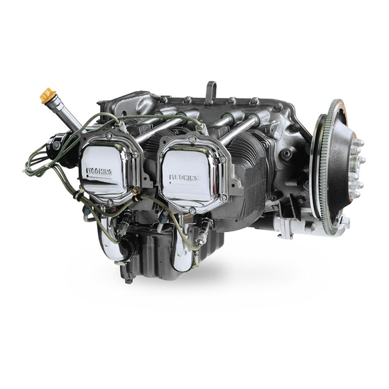
SECTION 1 DESCRIPTION The Lycoming O-235 series, O-290-D series and O-290-D2 series engines are four cylinder, direct drive, horizontally opposed, wet sump, air-cooled models. In referring to the location of the various engine components, the parts are described in their relationship to the engine as installed in conventional airframes. -
Page 12: Connecting Rods
LYCOMING OPERATOR’S MANUAL DESCRIPTION O-235 AND O-290 SERIES Connecting Rods – Made in the form of “H” sections from alloy steel forgings. They have replaceable bearing inserts in the crankshaft ends and split type bronze bushings in the piston ends. The bearing caps on the crankshaft ends are retained by means of two bolts and nuts through each cap. - Page 13 LYCOMING OPERATOR’S MANUAL SECTION 1 O-235 AND O290 SERIES DESCRIPTION TABLE 1 MODEL APPLICATION Magneto Propeller Flange Specification Model Carburetor (Modified) Left Right O-235-C S4LN-21 S4LN-20 MA-3A or –3PA AS-127-2 O-235-C1,-E1,-F1,-G1 S4LN-21 S4LN-20 MA-3A or –3PA AS-127-2 O-235-C1B,-E1B,-F1B,-G1B S4LN-200 S4LN-204 MA-3A or –3PA...
- Page 14 This Page Intentionally Left Blank.
-
Page 15: Specifications
Specifications – O-235-C, -E Series; O-235-C1C ..................2-1 Specifications – O-235-F, -G, -J, -N, -P, -K, -L, -M Series ............... 2-2 Specifications – O-235-H Series; O-235-K2C.................... 2-3 Specifications – O-290-D; O-290-D2, -D2A, -D2B, -D2C ................. 2-4 Accessory Drives ............................2-5 Alternate Power Settings..........................2-5... - Page 16 This Page Intentionally Left Blank.
- Page 17 LYCOMING OPERATOR’S MANUAL SECTION 2 O-235 AND O-290 SERIES SPECIFICATIONS SECTION 2 SPECIFICATIONS O-235-C*, -E SERIES FAA Type Certificate ............................223 Take-off horsepower............................115 Take-off RPM ..............................2800 Rated horsepower............................115 Rated RPM..............................2800 Bore, inches..............................4.375 Stroke, inches..............................3.875 Displacement, cubic inches.........................233.3 Compression ratio ............................. 6.50:1 Prop.
- Page 18 SECTION 2 LYCOMING OPERATOR’S MANUAL SPECIFICATIONS O-235 AND O-290 SERIES SPECIFICATIONS (CONT.) O-235-F, -G, -J FAA Type Certificate ............................223 Take-off horsepower............................125 Take-off RPM ..............................2800 Rated horsepower............................125 Rated RPM..............................2800 Bore, inches..............................4.375 Stroke, inches..............................3.875 Displacement, cubic inches.........................233.3 Compression ratio ............................9.7:1 Prop. drive ratio ............................. 1:1 Prop.
- Page 19 LYCOMING OPERATOR’S MANUAL SECTION 2 O-235 AND O-290 SERIES SPECIFICATIONS SPECIFICATIONS (CONT.) O-235-H FAA Type Certificate ............................223 Take-off horsepower............................115 Take-off RPM ..............................2800 Rated horsepower............................108 Rated RPM..............................2600 Bore, inches..............................4.375 Stroke, inches..............................3.875 Displacement, cubic inches.........................233.3 Compression ratio ............................. 6.75:1 Prop. drive ratio ............................. 1:1 Prop.
- Page 20 SECTION 2 LYCOMING OPERATOR’S MANUAL SPECIFICATIONS O-235 AND O-290 SERIES SPECIFICATIONS (CONT.) O-290-D FAA Type Certificate ............................229 Take-off horsepower............................130 Take-off RPM ..............................2800 Rated horsepower............................125 Rated RPM..............................2600 Bore, inches..............................4.875 Stroke, inches..............................3.875 Displacement, cubic inches.........................289.0 Compression ratio ............................. 6.50:1 Prop. drive ratio ............................. 1:1 Prop.
- Page 21 LYCOMING OPERATOR’S MANUAL SECTION 2 O-235 AND O290 SERIES SPECIFICATIONS SPECIFICATIONS (CONT.) Accessory Drive Drive Ratio *Direction of Rotation Starter 13.556:1 Counterclockwise Generator 1.910:1 Clockwise Generator (Optional) 2.500:1 Clockwise Alternator 3.250:1 Clockwise Vacuum Pump 1.300:1 Counterclockwise Hydraulic Pump 1.300:1 Counterclockwise Tachometer 0.500:1...
- Page 22 SECTION 2 LYCOMING OPERATOR’S MANUAL SPECIFICATIONS O-235 AND O-290 SERIES DETAIL WEIGHTS 1. STANDARD ENGINE (Average). MODEL LBS. O-235-C .................................240 O-235-C1B..............................241 O-235-C1, -C2A ............................242 O-235-C1C, -C2B, -H2C ..........................243 O-235-C2C..............................244 O-235-K2C, -L2C ............................248 O-235-E1B, -F1B, -N2C..........................249 O-235-E2A, -F2A ............................250 O-235-F2B ..............................251 O-235-K2A, -L2A, -N2A ..........................252...
-
Page 23: General
LYCOMING OPERATOR’S MANUAL SECTION 3 OPERATING INSTRUCTIONS Page General................................3-1 Prestarting Items of Maintenance ......................3-1 Starting Procedure............................3-1 Cold Weather Starting ..........................3-2 Ground Running and Warm-Up ........................ 3-2 Checks Before Take-Off ..........................3-3 Operation in Flight ............................3-3 Use of Carburetor Heat Control......................... - Page 24 This Page Intentionally Left Blank.
- Page 25 WILL NOT ONLY VOID YOUR WARRANTY BUT WILL SHORTEN THE LIFE OF YOUR ENGINE AFTER ITS WARRANTY PERIOD HAS PASSED. New engines have been carefully run-in by Lycoming and therefore no further break-in is necessary insofar as operation is concerned; however, new or newly overhauled engines should be operated using only the lubricating oils recommended in the latest revision of Service Instruction No.
- Page 26 SECTION 3 LYCOMING OPERATOR’S MANUAL OPERATING INSTRUCTIONS O-235 AND O-290 SERIES e. Set propeller governor (if applicable) in “Full RPM” position. f. Turn fuel valve to “on” position. g. Set throttle at ¼ travel. h. Move mixture control to “Full Rich”...
- Page 27 The procedures described in this manual provide proper fuel-air mixture when leaning Lycoming engines. They have proven to be both economical and practical by eliminating excessive fuel consumption and reducing damaged parts replacement.
- Page 28 SECTION 3 LYCOMING OPERATOR’S MANUAL OPERATING INSTRUCTIONS O-235 AND O-290 SERIES LEANING PRECAUTIONS Never exceed the maximum red line cylinder head temperature limit. For continuous operation cylinder head temperatures should be maintained below 435°F (224°C). On direct drive engines with manual mixture control, maintain mixture control in “Full Rich” position for rated take-off, rated maximum continuous, climb and cruise powers above 75%.
- Page 32 LYCOMING OPERATOR’S MANUAL SECTION 3 O-235 AND O-290 SERIES OPERATING INSTRUCTIONS OPERATING CONDITIONS Oil Pressure, psi – Model Maximum Minimum Idling Start and Warm-Up O-235 –C, -E, -F, -G, -H2C, -J, -K, -M O-235-B O-235-L*, -N O-235-P O-290-D O-290-D2 * - Front of engine Fuel Pressure, psi –...
- Page 33 SECTION 3 LYCOMING OPERATOR’S MANUAL OPERATING INSTRUCTIONS O-235 AND O-290 SERIES OPERATING CONDITIONS (CONT.) O-235-F, -G, -J Fuel Max. *Max. Cons. Oil Cons. Cyl. Head Operation Gal./Hr. Qts./Hr. Temp. Normal Rated 2800 10.7 0.56 500°F (260°C) Performance Cruise (75% Rated) 2500 0.31...
- Page 34 LYCOMING OPERATOR’S MANUAL SECTION 3 O-235 AND O-290 SERIES OPERATING INSTRUCTIONS OPERATING CONDITIONS (CONT.) O-235-N, -P Series Fuel Max. Max. Cons. Oil Cons. Cyl. Head Operation Gal./Hr. Qts./Hr. Temp. Take-Off 2800 ---- ---- 500°F (260°C) Normal Rated 2550 0.36 500°F (260°C)
- Page 35 SECTION 3 LYCOMING OPERATOR’S MANUAL OPERATING INSTRUCTIONS O-235 AND O-290 SERIES 9. SHUT-DOWN PROCEDURE. a. Idle engine at approximately 800 to 900 RPM until there is a decided drop in cylinder head temperature. b. Move mixture control to “Idle Cut-Off”.
- Page 36 LYCOMING OPERATOR’S MANUAL SECTION 3 O-235 AND O-290 SERIES OPERATING INSTRUCTIONS Figure 3-1. Power and Fuel Consumption Curve – O-235-C 3-11...
- Page 37 SECTION 3 LYCOMING OPERATOR’S MANUAL OPERATING INSTRUCTIONS O-235 AND O-290 SERIES Figure 3-2. Sea Level and Altitude Performance – O-235-C1, -E1, -H2 Series 3-12...
- Page 38 LYCOMING OPERATOR’S MANUAL SECTION 3 O-235 AND O-290 SERIES OPERATING INSTRUCTIONS Figure 3-3. Fuel Flow vs Percent Rated Power – O-235-C1, -E1, -H2 Series 3-13...
- Page 39 SECTION 3 LYCOMING OPERATOR’S MANUAL OPERATING INSTRUCTIONS O-235 AND O-290 SERIES Figure 3-4. Fuel Flow vs Percent Rated Power – O-235-F, -G, -J Series 3-14...
- Page 40 LYCOMING OPERATOR’S MANUAL SECTION 3 O-235 AND O-290 SERIES OPERATING INSTRUCTIONS Figure 3-5. Sea Level and Altitude Performance – O-235-F, -G, -J Series 3-15...
- Page 41 SECTION 3 LYCOMING OPERATOR’S MANUAL OPERATING INSTRUCTIONS O-235 AND O-290 SERIES Figure 3-6. Fuel Flow vs Percent Rated Power – O-235-K, -L, -M Series 3-16...
- Page 42 LYCOMING OPERATOR’S MANUAL SECTION 3 O-235 AND O-290 SERIES OPERATING INSTRUCTIONS Figure 3-7. Sea Level and Altitude Performance – O-235-K, -L, -M Series 3-17...
- Page 43 SECTION 3 LYCOMING OPERATOR’S MANUAL OPERATING INSTRUCTIONS O-235 AND O-290 SERIES Figure 3-8. Fuel Flow vs Horsepower – O-235-N, -P Series 3-18...
- Page 44 LYCOMING OPERATOR’S MANUAL SECTION 3 O-235 AND O-290 SERIES OPERATING INSTRUCTIONS Figure 3-9. Sea Level and Altitude Performance – O-235-N, -P Series 3-19...
- Page 45 SECTION 3 LYCOMING OPERATOR’S MANUAL OPERATING INSTRUCTIONS O-235 AND O-290 SERIES Figure 3-10. Power and Fuel Consumption Curve – O-290-D 3-20...
- Page 46 LYCOMING OPERATOR’S MANUAL SECTION 3 O-235 AND O-290 SERIES OPERATING INSTRUCTIONS Figure 3-11. Sea Level and Altitude Performance – O-290-D 3-21...
- Page 47 SECTION 3 LYCOMING OPERATOR’S MANUAL OPERATING INSTRUCTIONS O-235 AND O-290 SERIES Figure 3-12. Power and Fuel Consumption Curve – O-290-D2, -D2A 3-22...
- Page 48 LYCOMING OPERATOR’S MANUAL SECTION 3 O-235 AND O-290 SERIES OPERATING INSTRUCTIONS Figure 3-13. Sea Level and Altitude Performance Curve – O-290-D2, -D2A 3-23...
- Page 49 SECTION 3 LYCOMING OPERATOR’S MANUAL OPERATING INSTRUCTIONS O-235 AND O-290 SERIES Figure 3-14. Sea Level and Altitude Performance Curve - O-290-D2B, -D2C 3-24...
- Page 50 LYCOMING OPERATOR’S MANUAL SECTION 3 O-235 AND O-290 SERIES OPERATING INSTRUCTIONS USING CURVE TO FIND ACTUAL HORSEPOWER The following is an example of how to use the Sea Level and Altitude Performance curves, printed on these pages, to determine actual horsepower being delivered by the engine for given altitude, RPM, manifold pressure and air inlet temperature.
- Page 51 SECTION 3 LYCOMING OPERATOR’S MANUAL OPERATING INSTRUCTIONS O-235 AND O-290 SERIES Figure 3-15. Power and Fuel Consumption Curve – O-290-D2B, -D2C 3-26...
-
Page 53: Periodic Inspections
LYCOMING OPERATOR’S MANUAL SECTION 4 PERIODIC INSPECTIONS Page Prestarting Inspection ..........................4-1 Daily Pre-Flight............................4-2 25-Hour Inspection ............................4-2 50-Hour Inspection ............................4-2 100-Hour Inspection ............................ 4-3 400-Hour Inspection ............................ 4-4 Non-Scheduled Inspections ......................... 4-4... - Page 54 This Page Intentionally Left Blank.
- Page 55 LYCOMING OPERATOR’S MANUAL SECTION 4 O-235 AND O-290 SERIES PERIODIC INSPECTIONS SECTION 4 PERIODIC INSPECTIONS NOTE Perhaps no other factor is quite so important to safety and durability of the aircraft and its components as faithful and diligent attention to regular checks for minor troubles and prompt repair when they are found.
- Page 56 SECTION 4 LYCOMING OPERATOR’S MANUAL PERIODIC INSPECTIONS O-235 AND O-290 SERIES 1. DAILY PRE-FLIGHT. a. Be sure all switches are in the “Off” position. b. Be sure magneto ground wires are connected. c. Check oil level. d. See that fuel tanks are full.
- Page 57 LYCOMING OPERATOR’S MANUAL SECTION 4 O-235 AND O-290 SERIES PERIODIC INSPECTIONS Drain and refill sump with new oil on installation not employing replaceable external oil filter. See latest revision of Service Instruction No. 1014 for recommended lubricating oils. Seasonal grades are listed in Section 3, Paragraph 8 of this manual.
- Page 58 O-235 AND O-290 SERIES f. Priming Nozzles – Disconnect primer nozzles from engine and check for equal flow. g. Valve Rockers (O-235 and O-290-D) – Check clearance. See Page 5-9, Paragraph (11) for valve rocker clearance. h. Carburetor – Check throttle body attaching screws for tightness. The correct torque for these screws is 40 to 50 in.-lbs.
-
Page 59: Maintenance Procedures
LYCOMING OPERATOR’S MANUAL SECTION 5 MAINTENANCE PROCEDURES Page Ignition and Electrical System Ignition Harness and Wire Replacement....................5-1 Timing Magnetos to Engine ........................5-1 Generator and Alternator Output......................5-4 Fuel System Repair of Fuel Leaks..........................5-4 Carburetor Inlet Screen Assembly......................5-4 Fuel Grades and Limitations ........................ - Page 60 This Page Intentionally Left Blank.
- Page 61 LYCOMING OPERATOR’S MANUAL SECTION 5 O-235 AND O-290 SERIES MAINTENANCE PROCEDURES SECTION 5 MAINTENANCE PROCEDURES The procedures described in this section are provided to guide and instruct personnel in performing such maintenance operations that may be required in conjunction with the periodic inspections listed in the preceding section.
- Page 62 SECTION 5 LYCOMING OPERATOR’S MANUAL MAINTENANCE PROCEDURES O-235 AND O-290 SERIES FIRING ORDER 1-3-2-4 Figure 5-1. Ignition Wiring Diagram FIRING ORDER 1-3-2-4 Figure 5-2. Ignition Wiring Diagram (Optional)
- Page 63 LYCOMING OPERATOR’S MANUAL SECTION 5 O-235 AND O-290 SERIES MAINTENANCE PROCEDURES FIRING ORDER 1-3-2-4 Figure 5-3. Ignition Wiring Diagram (Optional) Conventional Magneto – Hold the No. 1 lead wire spring 1/8 in. away from the frame. Turn the gear counterclockwise vigorously through the flux lines until a strong spark occurs at the lead.
- Page 64 It is recommended that personnel be familiar with the latest revision of Service Instruction No. 1070 regarding specified fuel for Lycoming engines. d. Air Intake Ducts and Filter – Check all air intake ducts for dirt or restrictions. Inspect and service air filters as instructed in the airframe manufacturer’s handbook.
- Page 65 Oil Sump Capacity – O-235 Series........................6 U. S. Quarts O-290-D and –D2 Series .....................8 U. S. Quarts Minimum Safe Quantity in Sump ..................2 U. S. Quarts c. Oil Suction and Oil Pressure Screens – For engines without a full flow oil filter, change oil and inspect and clean screens every 25 hours.
- Page 66 LYCOMING OPERATOR’S MANUAL MAINTENANCE PROCEDURES O-235 AND O-290 SERIES e. Oil Relief Valve (Adjustable) – The adjustable oil relief valve enables the operator to maintain engine oil pressure within the specified limits. If the pressure under normal operating conditions should...
- Page 67 This is accomplished in the following manner: A special Lycoming tool is available for removal of the sockets and plunger assemblies. In the event the tool is not available, proceed as described below.
- Page 68 LYCOMING OPERATOR’S MANUAL MAINTENANCE PROCEDURES O-235 AND O-290 SERIES (2) Assemble piston so that the cylinder number stamped on the piston pin boss is toward the front end of the engine. The piston pin should be a push fit. If difficulty is experienced in inserting the piston pin, it is probably caused by carbon or burrs in the piston pin hole.
- Page 69 (10) O-290-D2 Series – Be sure that the piston is at top center compression stroke and that both valves are closed. Check clearance between the valve stem tip and the valve rocker. In order to check this clearance, place the thumb of one hand on the valve rocker directly over the end of the push rod and push down so as to compress the hydraulic tappet spring.
- Page 70 This Page Intentionally Left Blank.
-
Page 71: Trouble-Shooting
LYCOMING OPERATOR’S MANUAL SECTION 6 TROUBLE-SHOOTING Page Failure of Engine to Start..........................6-1 Failure of Engine to Idle Properly......................6-1 Low Power and Uneven Running....................... 6-2 Failure of Engine to Develop Full Power....................6-2 Rough Engine ............................... 6-3 Low Oil Pressure............................6-3 High Oil Temperature .......................... - Page 72 This Page Intentionally Left Blank.
- Page 73 LYCOMING OPERATOR’S MANUAL SECTION 6 O-235 AND O-290 SERIES TROUBLE-SHOOTING SECTION 6 TROUBLE-SHOOTING General – Experience has proven the best method of “trouble-shooting” is to decide on the various possible causes of a given trouble and then to eliminate these causes one by one, beginning with the most probable.
- Page 74 SECTION 6 LYCOMING OPERATOR’S MANUAL TROUBLE-SHOOTING O-235 AND O-290 SERIES TROUBLE PROBABLE CAUSE REMEDY Low Power and Uneven Running Mixture too rich; indicated by Check primer shut-off valve for sluggish engine operation, red leakage. Readjustment of exhaust flange at night. Extreme...
- Page 75 LYCOMING OPERATOR’S MANUAL SECTION 6 O-235 AND O-290 SERIES TROUBLE-SHOOTING TROUBLE PROBABLE CAUSE REMEDY Rough Engine Cracked engine mount. Replace mount. Unbalanced propeller. Remove propeller and have it checked for balance. Defective mounting bushings. Install new mounting bushings. Malfunctioning engine.
- Page 76 SECTION 6 LYCOMING OPERATOR’S MANUAL TROUBLE-SHOOTING O-235 AND O-290 SERIES TROUBLE PROBABLE CAUSE REMEDY Excessive Oil Consumption Low grade of oil. Fill tank with oil conforming to specification. Failing or failed bearing. Check sump for metal particles. Worn piston rings.
-
Page 77: Installation And Storage
LYCOMING OPERATOR’S MANUAL SECTION 7 INSTALLATION AND STORAGE Page Preparation of Engine for Installation....................... 7-1 General............................... 7-1 Inspection of Engine Mounting ....................... 7-1 Attaching Engine to Mounts ........................7-1 Oil and Fuel Line Connections ........................ 7-1 Propeller Installation ..........................7-1 Preparation of Carburetor for Installation .................... - Page 78 This Page Intentionally Left Blank.
- Page 79 LYCOMING OPERATOR’S MANUAL SECTION 7 O-235 AND O-290 SERIES INSTALLATION AND STORAGE SECTION 7 INSTALLATION AND STORAGE 1. PREPARATION OF ENGINE FOR INSTALLATION. Before installing an engine that has been prepared for storage, remove all dehydrator plugs, bags of desiccant and preservative oil from the engine.
- Page 80 SECTION 7 LYCOMING OPERATOR’S MANUAL INSTALLATION AND STORAGE O-235 AND O-290 SERIES 2. PREPARATION OF CARBURETOR FOR INSTALLATION. Carburetors that have been prepared for storage should undergo the following procedures before being placed in service. Carburetor – Remove the fuel drain plug and drain preservative oil. Remove the fuel inlet strainer assembly and clean in a hydrocarbon solvent.
- Page 81 INSTALLATION AND STORAGE NOTE Oils of the type mentioned are to be use in Lycoming aircraft for corrosion prevention only, and not for lubrication. See the latest revision of Lycoming Service Instruction No. 1014 and Service Bulletin No. 318 for recommended lubricating oil.
- Page 82 SECTION 7 LYCOMING OPERATOR’S MANUAL INSTALLATION AND STORAGE O-235 AND O-290 SERIES Figure 7-3. Installation Drawings...
-
Page 83: Tables
LYCOMING OPERATOR’S MANUAL SECTION 8 TABLES Page Table of Limits ............................. 8-1 Inspection Forms After Top Overhaul or Cylinder Change with New Rings Ground Run............................8-2 Flight Test ............................... 8-3 Full Throttle HP at Altitude........................8-4 Table of Speed Equivalents ......................... 8-4 Centigrade-Fahrenheit Conversion Table.................... - Page 84 This Page Intentionally Left Blank.
- Page 85 RECOMMENDATIONS INFORMATION CONCERNING TOLERANCES AND DIMENSIONS THAT MUST BE MAINTAINED IN LYCOMING AIRCRAFT ENGINES, CONSULT LATEST REVISION OF SPECIAL SERVICE PUBLICATION NO. SSP-1776. CONSULT LATEST REVISION OF SERVICE INSTRUCTION NO. 1029 AND NO. 1150 FOR INFORMATION PERTINENT TO CORRECTLY INSTALLING CYLINDER...
- Page 86 SECTION 8 LYCOMING OPERATOR’S MANUAL TABLES O-235 AND O-290 SERIES...
- Page 87 LYCOMING OPERATOR’S MANUAL SECTION 8 O-235 AND O-290 SERIES TABLES...
- Page 88 SECTION 8 LYCOMING OPERATOR’S MANUAL TABLES O-235 AND O-290 SERIES FULL THROTTLE HP AT ALTITUDE (Normally Aspirated Engines) Altitude % S.L. Altitude % S.L. Altitude % S.L. H.P. H.P. H.P. 10,000 70.8 19,500 49.1 98.5 11,000 68.3 20,000 48.0 1,000 96.8...
- Page 89 LYCOMING OPERATOR’S MANUAL SECTION 8 O-235 AND O-290 SERIES TABLES CENTIGRADE-FAHRENHEIT CONVERSION TABLE Example: To convert 20°C to Fahrenheit, find 20 in the center column headed (F-C); then read 68.0°F in the column (F) to the right. To convert 20°F to Centigrade; find 20 in the center column and read –6.67°C in the (C) column to the left.
- Page 90 SECTION 8 LYCOMING OPERATOR’S MANUAL TABLES O-235 AND O-290 SERIES INCH FRACTIONS CONVERSIONS Decimals, Area of Circles and Millimeters Inch Decimal Area Inch Decimal Area Fraction Equiv. Sq. In. Equiv. Fraction Equiv. Sq. In. Equiv. 1/64 .0156 .0002 .397 .1964 12.700...
Need help?
Do you have a question about the O-290 and is the answer not in the manual?
Questions and answers