
Related Manuals for Hirschmann RSP 25


Summary of Contents for Hirschmann RSP 25
- Page 1 User Manual Installation Industrial Ethernet Rail Switch Power RSP 20/25/30/35 Installation RSP 20/25/30/35 Technical support Release 15 12/2017 https://hirschmann-support.belden.eu.com...
- Page 2 In addition, we refer to the conditions of use specified in the license contract. You can get the latest version of this manual on the Internet at the Hirschmann product site (www.hirschmann.com). Hirschmann Automation and Control GmbH Stuttgarter Str.
-
Page 3: Table Of Contents
Contents Safety instructions About this manual Description General description Device name and product code Device views 1.3.1 Front view 1.3.2 Rear view Power supply 1.4.1 Supply voltage with the characteristic value K9 1.4.2 Supply voltage with the characteristic value KK 1.4.3 Supply voltage with the characteristic value TT 1.4.4 Supply voltage with the characteristic value CC Ethernet ports... - Page 4 Connecting the terminal blocks 2.5.1 Supply voltage with the characteristic value K9 2.5.2 Supply voltage with the characteristic value KK 2.5.3 Supply voltage with the characteristic value CC 2.5.4 Supply voltage with the characteristic value TT 2.5.5 Signal contact Operating the device Connecting data cables Filling out the inscription label Making basic settings...
-
Page 5: Safety Instructions
Certified usage Use the product only for the application cases described in the Hirschmann product information, including this manual. Operate the product only according to the technical specifications. See “Technical data” on page 49. Connect to the product only components suitable for the requirements of the specific application case. - Page 6 Device casing Only technicians authorized by the manufacturer are permitted to open the housing. Never insert pointed objects (narrow screwdrivers, wires, etc.) into the device or into the connection terminals for electric conductors. Do not touch the connection terminals. ...
- Page 7 All of the following requirements are complied with: The electrical wires are voltage-free. The cables used are permitted for the temperature range of the application case. Table 1: General requirements for connecting electrical wires All of the following requirements are complied with: ...
- Page 8 Device variant Requirements Only device variants The wire diameter of the power supply cable is at least 0.75 mm² (North featuring supply America: AWG18) on the supply voltage input. voltage with The following requirements are alternatively complied with: characteristic value Alternative 1 The power supply complies with the requirements for a limited power source (LPS) as per EN 60950-1.
- Page 9 ATEX directive 2014/34/EU – specific regulations for safe operation Relevant for RSP devices when operating in explosive gas atmospheres according to ATEX directive 2014/34/EU, the following applies: List of standards: EN 60079-0:2012, A11:2013 EN 60079-15:2010 Certificate No.: DEKRA 15ATEX0017X ...
- Page 10 Relevant for use in explosion hazard areas (Hazardous Locations, Class I, Division 2): The relay connections are to be installed and used within their Entity Parameters as per Control Drawing 000189237DNR. Avertissement - Risque d'explosion - Ne pas débrancher tant que le circuit est sous tension à...
- Page 11 For Use in Hazardous Locations Class I Division 2 Groups A, B, C, D: Only allowed for RSP 20/25/30/35 model No´s. which are individually labeled “FOR USE IN HAZARDOUS LOCATIONS”. Nonincendive fi eld wiring circuits must be wired in accordance with the National Electrical Code (NEC), NFPA 70, article 501;...
- Page 12 Ordinary Location, Explosive Atmosphere Non-Hazardous Area, Class I Division 2 Groups A, B, C, D Non-Explosive Atmosphere Hazardous Location Relay contacts: Equipment with nonincendive ¿ eld wiring parameters. Polarity is not relevant. The relay terminals are dependent upon the following Entity parameters: 30 V 90 mA...
- Page 13 IECEx – Certification Scheme for Explosive Atmospheres For RSP devices labeled with an IECEx certificate number, the following applies: List of standards: IEC 60079-0:2011+Cor.2012+Cor.2013 IEC 60079-15:2010 The equipment shall only be used in an area of not more than pollution degree 2, as defined in IEC 60664-1.
- Page 14 In accordance with the above-named EU directive(s), the EU conformity declaration will be at the disposal of the relevant authorities at the following address: Hirschmann Automation and Control GmbH Stuttgarter Str. 45-51 72654 Neckartenzlingen Germany The product can be used in the industrial sector.
- Page 15 FCC note: This device complies with part 15 of the FCC rules. Operation is subject to the following two conditions: (1) this device may not cause harmful interference; (2) this device must accept any interference received, including interference that may cause undesired operation. Appropriate testing has established that this device fulfills the requirements of a class A digital device in line with part 15 of the FCC regulations.
-
Page 16: About This Manual
The “Installation” user manual contains a device description, safety instructions, a description of the display, and the other information that you need to install the device. The following manuals are available as PDF files on the Internet on the Hirschmann product pages (www.hirschmann.com): Installation user manual ... - Page 17 The symbols used in this manual have the following meanings: Listing Work step Subheading Installation RSP 20/25/30/35 Release 15 12/2017...
-
Page 18: Description
The devices provide you with a large range of functions, which the manuals for the operating software inform you about. You find these manuals in the form of PDF files for downloading on the Internet on the Hirschmann product pages (www.hirschmann.com). -
Page 19: Device Name And Product Code
The Hirschmann network components help you ensure continuous communication across all levels of the company. Device name and product code The device name corresponds to the product code. The product code is made up of characteristics with defined positions. The characteristic values stand for specific product properties. - Page 20 See table 5 on page 21. 22 ... 23 Customer-specific Hirschmann Standard version Hirschmann Fast MRP Hirschmann PRP Hirschmann HSR From software version 05.0 onward: Hirschmann DLR Note: You can exchange software with each other on the following device variants: ...
- Page 21 Application case Certificates and Characteristic value declarations Standard ATEX, Zone 2/IECEx applications ISA-12.12.01 – Class I, Div. 2 EN 61131-2 UL 508 Substation IEC 61850-3 applications IEEE 1613 Navy applications GL Railway EN 50121-4 applications (trackside) Table 5: Assignment: application cases, certificates and declarations, characteristic values...
-
Page 22: Device Views
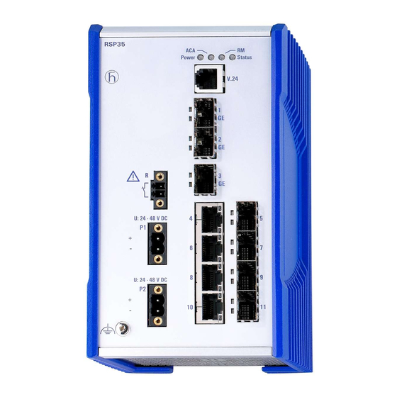
Device views 1.3.1 Front view Front view (using the example RSP20-11003Z6TT-SCC...) LED display elements for device status V.24 interface 3 × SFP slot for 100 Mbit/s connections 8 × 10/100 Mbit/s twisted pair ports Grounding screw Supply voltage connection alternatively, Supply voltage with the ... -
Page 23: Rear View
1.3.2 Rear view Slot for the SD card Thumb screw Installation RSP 20/25/30/35 Release 15 12/2017... -
Page 24: Supply Voltage With The Characteristic Value K9
Power supply You will find information on the characteristic values here: “Device name and product code” on page 19 1.4.1 Supply voltage with the characteristic value K9 For the power supply of the device, a 3-pin terminal block is available. Further information: See “Supply voltage with the characteristic value K9”... -
Page 25: Ethernet Ports
Ethernet ports You can connect end devices and other segments to the device ports using twisted pair cables or optical fibers (F/O). 1.5.1 10/100 Mbit/s twisted pair port This port is an RJ45 socket. The 10/100 Mbit/s twisted pair port allows you to connect network components according to the IEEE 802.3 10BASE-T/100BASE-TX standard. -
Page 26: Mbit/S F/O Port (Optional)
1.5.4 100/1000 Mbit/s F/O port (optional) This port is an SFP slot. The 100/1000 Mbit/s F/O port allows you to connect network components according to the IEEE 802.3 100BASE-FX/1000BASE-SX/1000BASE-LX standard. This port supports: 1000 Mbit/s full duplex 100 Mbit/s half-duplex mode, 100 Mbit/s full duplex mode State on delivery: ... -
Page 27: Display Elements
Display elements After the supply voltage is set up, the software starts and initializes itself. Afterwards, the device performs a self-test. During this process, various LEDs light up. 1.6.1 Device state These LEDs provide information about conditions which affect the operation of the whole device. -
Page 28: Port Status
Applies to software releases after 02.0.00: Display Color Activity Meaning Status Device Status — none Device is starting and/or is not ready for operation green Lights up Device is ready for operation. Characteristics can be configured Lights up Device is ready for operation. Device has detected at least one error in the monitoring results Flashes 1 time... -
Page 29: Management Interfaces
For information about the position on the device see “Rear view” on page On the front of the device there is an LED display that informs you about the status of the interface. Only use Hirschmann SD cards. Installation RSP 20/25/30/35 Release 15 12/2017... -
Page 30: Signal Contact
Signal contact Figure 2: Signal contact: 2-pin terminal block with screw locking The signal contact is a potential-free relay contact. The device allows you to perform remote diagnosis via the signal contact. In the process, the device signals events such as a line interruption. When an event occurs, the device opens the relay contact and interrupts the closed circuit. -
Page 31: Installation
Installation The devices have been developed for practical application in a harsh industrial environment. On delivery, the device is ready for operation. Perform the following steps to install and configure the device: Checking the package contents Installing the SD card (optional) ... -
Page 32: Installing The Sd Card (Optional)
Installing the SD card (optional) Note: Only use the AutoConfiguration Adapter ACA31 storage medium. See “Accessories” on page 60. Proceed as follows: Deactivate the write protection on the SD card by pushing the write- protect lock towards the middle of the card. ... -
Page 33: Installing The Device Onto The Din Rail
2.3.1 Installing the device onto the DIN rail Verify that the device maintains the minimum clearing in order to meet the climatic conditions: Top and bottom device side: 3.94 in (10 cm) Left and right device side: 0.79 in (2 cm) Undercutting the minimum clearing reduces the specified maximum operating temperature. -
Page 34: Grounding The Device
Ground the device via the ground screw. Installing an SFP transceiver (optional) Use only Hirschmann SFP transceivers which are suitable for usage with the device. See “Accessories” on page 60. Proceed as follows: ... -
Page 35: Connecting The Terminal Blocks
Connecting the terminal blocks WARNING ELECTRIC SHOCK Before connecting the electrical wires, always verify that the requirements listed are complied with. See “Requirements for connecting electrical wires” on page 6. Never insert sharp objects (small screwdrivers, wires, etc.) into the connection terminals for electric conductors, and do not touch the terminals. - Page 36 Type of the voltages Specification of the supply Pin assignment that can be voltage connected AC voltage Rated voltage range AC Outer conductor 110 V AC ... 230 V AC, −/N Neutral conductor 50 Hz ... 60 Hz Protective conductor Voltage range AC including maximum tolerances 88 V AC ...
-
Page 37: Supply Voltage With The Characteristic Value Kk
2.5.2 Supply voltage with the characteristic value KK You will find information on the characteristic values here: “Device name and product code” on page 19 You have the option of supplying the supply voltage redundantly, without load distribution. Both supply voltage inputs are uncoupled. With a redundant supply, the supply voltage 1 (upper voltage input on the device) has priority. - Page 38 WARNING ELECTRIC SHOCK Install this device solely in a switch cabinet or in an operating site with restricted access, to which maintenance staff have exclusive access. Failure to follow this instruction can result in death, serious injury, or equipment damage. ...
-
Page 39: Supply Voltage With The Characteristic Value Cc
2.5.3 Supply voltage with the characteristic value CC You will find information on the characteristic values here: “Device name and product code” on page 19 You have the option of supplying the supply voltage redundantly, without load distribution. Both supply voltage inputs are uncoupled. −... -
Page 40: Supply Voltage With The Characteristic Value Tt
2.5.4 Supply voltage with the characteristic value TT You will find information on the characteristic values here: “Device name and product code” on page 19 You have the option of supplying the supply voltage redundantly, without load distribution. Both supply voltage inputs are uncoupled. −... -
Page 41: Signal Contact
2.5.5 Signal contact Connect the signal contact wires with the connectors of the terminal block. Fasten the wires connected by tightening the terminal screws. You find the prescribed tightening torque in chapter: “General technical data” on page 49 Operating the device WARNING ELECTRIC SHOCK... -
Page 42: Connecting Data Cables
Connecting data cables Note the following general recommendations for data cable connections in environments with high electrical interference levels: Keep the length of the data cables as short as possible. Use optical data cables for the data transmission between the buildings. ... -
Page 43: Making Basic Settings
Making basic settings The IP parameters must be entered when the device is installed for the first time. The device provides the following options for configuring IP addresses: Input via the V.24 interface Entry via the HiDiscovery protocol in the applications HiDiscovery or Industrial HiVision ... -
Page 44: Upgrading Software
Upgrading Software The upgrade options for RSP 20/25/30/35 device depend on the software level of the device. See “Device name and product code” on page 19. Note: For software version 04.0 or higher, “HiOS” is available as a common software image for the software levels 2A and 3S. You select only the desired redundancy function during the installation of the image. -
Page 45: Monitoring The Ambient Air Temperature
Monitoring the ambient air temperature Operate the device below the specified maximum ambient air temperature exclusively. See “General technical data” on page 49. The ambient air temperature is the temperature of the air at a distance of 2 in (5 cm) from the device. It depends on the installation conditions of the device, e.g. -
Page 46: Maintenance And Service
Hirschmann is continually working on improving and developing their software. Check regularly whether there is an updated version of the software that provides you with additional benefits. You find information and software downloads on the Hirschmann product pages on the Internet (http://www.hirschmann.com). ... -
Page 47: Disassembly
Disassembly Removing the device WARNING ELECTRIC SHOCK Disconnect the grounding only after disconnecting all other cables. Failure to follow this instruction can result in death, serious injury, or equipment damage. Proceed as follows: Disconnect the data cables. Disable the supply voltage. ... -
Page 48: Removing An Sfp Transceiver (Optional)
Removing an SFP transceiver (optional) Proceed as follows: Pull the SFP transceiver out of the slot by means of the opened lock. Seal the SFP transceiver with the protection cap. Installation RSP 20/25/30/35 Release 15 12/2017... -
Page 49: Technical Data
Technical data General technical data Dimensions RSP 20/25/30/35 See “Dimension drawings” on page 53. W × H × D Weight RSP 20/25/30/35-..TT-S..approx. 2.65 lb (1.2 kg) RSP 20/25/30/35-..TT-T..approx. 3.31 lb (1.5 kg) RSP 20/25/30/35-..TT-E..RSP 20/25/30/35-..ZT-S..approx. 1.3 kg RSP 20/25/30/35-..ZT-T.. - Page 50 (10 cm) operation Left and right device side: 0.79 in (2 cm) Derating refer to the Hirschmann product web page under http://www.hirschmann.com Ambient air temperature Devices with operating temperature characteristic value S (standard): +32 °F ... +140 °F (0 °C ... +60 °C)
- Page 51 Temperature of the ambient air at a distance of 2 in (5 cm) from the device c. Hirschmann recommends to use SFP transceivers with “EEC” extension. d. Use SFP transceivers with the “EEC” extension only, otherwise the standard temperature range applies.
-
Page 52: Power Consumption/Power Output
Power consumption/power output Device name Maximum Power output power consumption RSP20-11003Z6TT... Supply voltage with characteristic value CC, K9 or KK 15 W 51 Btu (IT)/h Supply voltage with characteristic value TT 17 W 58 Btu (IT)/h RSP20-11003Z6ZT... Supply voltage with characteristic value CC, K9 or KK 18 W 61 Btu (IT)/h Supply voltage with characteristic value TT... -
Page 53: Dimension Drawings
Dimension drawings 114,7 6,55 4.52 inch 0.26 2.76 89,9 3.54 Figure 7: Dimensions of the device variants with operating temperature characteristic value S. For the characteristic value, cf. “Device name and product code” on page 114,7 6,55 4.52 inch 0.26 2.76 98,29 3.87... -
Page 54: Emc And Immunity
EMC and immunity You will find detailed information on the certificates and declarations applying to your device in a separate overview. See table 5 on page 21. Stability Standard applications Substation applications IEC 60068-2-6, test Fc Vibration — 2 Hz ... 9 Hz with 0.12 in. (3 mm) amplitude 5 Hz ... - Page 55 EMC interference immunity Standard applications Substation applications Electrostatic discharge EN 61000-4-2 Contact discharge ±4 kV ±8 kV IEEE C37.90.3 EN 61000-4-2 Air discharge ±8 kV ± 15 kV IEEE C37.90.3 Electromagnetic field EN 61000-4-3 80 MHz ... 3000 MHz 10 V/m 10 V/m IEEE 1613 80 MHz ...
- Page 56 EMC interference immunity Standard applications Substation applications Damped oscillation - data line EN 61000-4-12 line/ground — 2.5 kV IEEE C37.90.1 EN 61000-4-12 line/line — 1 kV Pulse magnetic fields EN 61000-4-9 — 300 A/m...
-
Page 57: Network Range
Network range Note: The line lengths specified for the transceivers apply for the respective fiber data (fiber attenuation and BLP/dispersion). Product code Mode Wave length Fiber System Example for F/O Fiber attenuation BLP /Dispersion M-SFP-... attenuation cable length -SX/LC... 850 nm 50/125 µm 0 dB ... - Page 58 a. MM = Multimode, SM = Singlemode, LH = Singlemode Longhaul b. Including 3 dB system reserve when compliance with the fiber data is observed. c. Using the bandwidth-length product is inappropriate for expansion calculations. d. With F/O adapter compliant with IEEE 802.3-2002 Clause 38 (single-mode fiber offset-launch mode conditioning patch cord). e.
- Page 59 Product code Mode Wave length Fiber System Example for F/O Fiber attenuation BLP/Dispersion M-FAST-SFP-... attenuation cable length -MM/LC... 1310 nm 50/125 µm 0 dB ... 8 dB 0 mi ... 3.11 mi 1.0 dB/km 800 MHz×km (0 km ... 5 km) -MM/LC...
-
Page 60: Scope Of Delivery, Order Numbers And Accessories
Scope of delivery, order numbers and accessories Scope of delivery Number Article 1 × Device 1 × General safety instructions 1 × 2-pin terminal block for signal contact 1 × 3-pin terminal block for the supply voltage (only for device variants featuring supply voltage with characteristic value K9) 2 ×... - Page 61 M-SFP-LH+/LC EEC 942 119-001 SFP-GIG-LX/LC 942 196-001 SFP-GIG-LX/LC EEC 942 196-002 a. You find further information on certifications on the Internet at the Hirschmann product pages (www.hirschmann.com). Bidirectional Gigabit Ethernet SFP transceiver Order number M-SFP-BIDI Type A LX/LC EEC 943 974-001...
- Page 62 M-FAST SFP-LH/LC EEC 943 948-001 SFP-FAST-MM/LC 942 194-001 SFP-FAST-MM/LC EEC 942 194-002 SFP-FAST-SM/LC 942 195-001 SFP-FAST-SM/LC EEC 942 195-002 a. You find further information on certifications on the Internet at the Hirschmann product pages (www.hirschmann.com). Installation RSP 20/25/30/35 Release 15 12/2017...
-
Page 63: Underlying Technical Standards
Underlying technical standards Name CSA C22.2 No. 142 Canadian National Standard(s) – Process Control Equipment – Industrial Products ANSI/ISA-12.12.01 Nonincendive Electrical Equipment for Use in Class I and II, Division 2 and Class III, Divisions 1 and 2 Hazardous (Classified) Locations EN 55032 Electromagnetic compatibility of multimedia equipment –... -
Page 64: A Further Support
Further support Technical questions For technical questions, please contact any Hirschmann dealer in your area or Hirschmann directly. You find the addresses of our partners on the Internet at http://www.hirschmann.com. A list of local telephone numbers and email addresses for technical support directly from Hirschmann is available at https://hirschmann-support.belden.eu.com. - Page 65 Installation RSP 20/25/30/35 Release 15 12/2017...
Need help?
Do you have a question about the RSP 25 and is the answer not in the manual?
Questions and answers