
Related Manuals for Hirschmann RSPE 30


Summary of Contents for Hirschmann RSPE 30
-
Page 1: User Manual
User Manual Installation Industrial Ethernet Rail Switch Power Enhanced RSPE 30/32/35/37 Installation RSPE 30/32/35/37 Technical support Release 12 10/2015 https://hirschmann-support.belden.eu.com... - Page 2 In addition, we refer to the conditions of use specified in the license contract. You can get the latest version of this manual on the Internet at the Hirschmann product site (www.hirschmann.com). Hirschmann Automation and Control GmbH Stuttgarter Str.
-
Page 3: Table Of Contents
1.7.2 SD card interface 1.7.3 USB interface Signal contact Installation Checking the package contents Installing the SD card (optional) Mounting a dummy panel or a media module 2.3.1 Mounting a dummy panel 2.3.2 Mounting a media module Installation RSPE 30/32/35/37 Release 12 10/2015... - Page 4 Filling out the inscription label Making basic settings Upgrading Software Monitoring the ambient air temperature Maintenance and service Disassembly Removing the device Removing an SFP transceiver (optional) Removing a media module (optional) Technical data Further Support Installation RSPE 30/32/35/37 Release 12 10/2015...
-
Page 5: Safety Instructions
Certified usage Use the product only for the application cases described in the Hirschmann product information, including this manual. Operate the product only according to the technical specifications. See “Technical data” on page 53. Connect to the product only components suitable for the requirements of the specific application case. -
Page 6: Grounding The Device
Beware of possible short circuits when connecting a cable section with conductive shielding braiding. Requirements for connecting electrical wires Before connecting the electrical wires, always verify that the requirements listed are complied with. Installation RSPE 30/32/35/37 Release 12 10/2015... - Page 7 The minus conductor is on ground potential. Otherwise, a fuse is also located in the minus conductor. Regarding the properties of this fuse: See “General technical data” on page 53. Table 3: Requirements for connecting the supply voltage Installation RSPE 30/32/35/37 Release 12 10/2015...
- Page 8 The supply voltage is connected to the device casing through protective elements exclusively. For supply voltage connections with protective conductor connection: First connect the protective conductor before connecting the wires for the supply voltage. Installation RSPE 30/32/35/37 Release 12 10/2015...
- Page 9 Provisions shall be made to prevent the rated voltage from being exceeded by transient disturbances of more than 119 V. Connectors shall be connected or disconnected exclusively in dead- voltage state. The USB port shall remain disconnected. Installation RSPE 30/32/35/37 Release 12 10/2015...
- Page 10 Ne pas debrancher tant que le circuit est sous tension a moins que l‘emplacement soit connu pour Control Drawing for RSPE devices according to Class 1 Division 2 Hazardous Locations Rev.: 1 Document No.: 000182303DNR Page 1/2 Installation RSPE 30/32/35/37 Release 12 10/2015...
- Page 11 (“Cable C ” denotes the capacitance per unit length of used cable) The lower value of (a) and (b) is to apply. Control Drawing for RSPE devices according to Class 1 Division 2 Hazardous Locations Rev.: 1 Document No.: 000182303DNR Page 2/2 Installation RSPE 30/32/35/37 Release 12 10/2015...
- Page 12 Connectors shall be connected or disconnected exclusively in dead- voltage state. The USB port shall remain disconnected. CE marking The labeled devices comply with the regulations contained in the following European directive(s): Installation RSPE 30/32/35/37 Release 12 10/2015...
- Page 13 LED or LASER components according to IEC 60825-1 (2014): CLASS 1 LASER PRODUCT CLASS 1 LED PRODUCT Note: You will find additional warning and safety information in the “User Manual Installation Installation RSPE 30/32/35/37“ supplied with every RSPE 30/32/35/37 device. Installation RSPE 30/32/35/37 Release 12 10/2015...
- Page 14 Recycling note After usage, this device must be disposed of properly as electronic waste, in accordance with the current disposal regulations of your county, state, and country. Installation RSPE 30/32/35/37 Release 12 10/2015...
-
Page 15: About This Manual
Event log Simultaneous configuration of multiple devices Graphical user interface with network layout SNMP/OPC gateway The symbols used in this manual have the following meanings: Listing Work step Subheading Installation RSPE 30/32/35/37 Release 12 10/2015... -
Page 16: Description
Description General description The RSPE 30/32/35/37 devices are designed for the special requirements of industrial automation. They meet the relevant industry standards, provide very high operational reliability, even under extreme conditions, and also long-term reliability and flexibility. You can choose from between a wide range of variants. You have the option to set up your device individually based on different criteria: ... -
Page 17: Device Name And Product Code
PDF files on the enclosed CD/DVD, or you can download them from the Internet on the Hirschmann product pages (www.hirschmann.com). The Hirschmann network components help you ensure continuous communication across all levels of the company. Device name and product code The device name corresponds to the product code. - Page 18 HiOS Layer 3 Standard 32 ... 36 Software version 03.1. Software version 03.1 XX.X. Current software version 37 ... 38 Maintenance Bugfix version 00 Current bugfix version Table 4: Device name and product code Installation RSPE 30/32/35/37 Release 12 10/2015...
- Page 19 Application case Certificates and Characteristic value declarations Z9 X9 W9 WX WU WD WC WB WA U9 UY UX UW T9 TY V9 VP VU P9 Standard applications ATEX, Zone 2 IECEx EN 60950-1 EN 61131-2 ISA 12.12.01 – Class I, Div. 2 UL 61010-1, UL 61010-2-210 UL 60950-1 Substation applications...
-
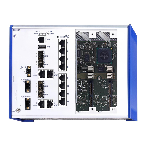
Page 20: Device Views
2 voltage inputs for redundant power the characteristic supply 3-pin terminal block value: Supply voltage with 2 voltage inputs for redundant power the characteristic supply value: 2-pin terminal block Grounding screw Connection for the signal contact Installation RSPE 30/32/35/37 Release 12 10/2015... -
Page 21: Rear View
USB interface V.24 interface a. only for twisted pair connections 1.3.2 Rear view Slot for the SD card Knurled screw Installation RSPE 30/32/35/37 Release 12 10/2015... -
Page 22: Power Supply
IEEE 802.3 (insulation resistance 48 V, output to the “rest of the world” 750 V DC for 60 seconds). For further information see “Supply voltage with characteristic value PP” on page Installation RSPE 30/32/35/37 Release 12 10/2015... -
Page 23: Ethernet Ports
Note: By using media modules, you obtain up to 16 additional Fast Ethernet ports on a RSPM basic device. You will find more information on the media modules in the “User Manual for Installation of RSPM”. Installation RSPE 30/32/35/37 Release 12 10/2015... -
Page 24: 10/100 Mbit/S Twisted Pair Port
The socket housing is electrically connected with the front panel. 1.5.2 Gigabit combo port The RSPE 30/32/35/37 device provides 4 combo ports for transmission speeds of up to 1000 Mbit/s. See table 6 on page 23. You have the option of alternatively connecting a twisted pair cable via a RJ45 socket or an optical fiber via a SFP transceiver to a combo port. -
Page 25: 100 Mbit/S F/O Port (Optional)
Note: Insert the media module with 8 F/O ports only in the media module slot 2. See “Device views” on page 20. You will find more information on the media modules in the “User Manual for Installation of RSPM”. Installation RSPE 30/32/35/37 Release 12 10/2015... -
Page 26: Support Of Poe(+)
IEEE 802.3at Brief description PoE+ Classes max. Powered Device (PD) class 4 (30 W) Table 7: PoE support: technical standards In accordance with IEEE 802.3af and IEEE 802.3at: Endpoint PSE Alternative A. Installation RSPE 30/32/35/37 Release 12 10/2015... -
Page 27: Pin Assignments
RX− BI_DB− Negative V BI_DA+ Positive V — BI_DD+ Positive V — BI_DD− Positive V TX− BI_DA− Positive V — BI_DC+ Negative V — BI_DC− Negative V a. Phantom supply b. Spare pair supply Installation RSPE 30/32/35/37 Release 12 10/2015... -
Page 28: Display Elements
The boot parameters used when the a period device has been started differ from the boot parameters saved. Start the device again. flashes 4 times Device has detected a multiple IP address a period Installation RSPE 30/32/35/37 Release 12 10/2015... -
Page 29: Media Module Status
1.6.2 Media module status Device variants RSPE 30 and RSPE 35 1 LED is located on the upper part of the media module. This LED provides information on the supply voltage status of the media module. Power Display Color... -
Page 30: Port State
Device detects a non-supported SFP transceiver or a non-supported data rate Flashing Device is transmitting and/or receiving data Flashes 1 time a period Device detects at least one unauthorized MAC address (Port Security Violation) Installation RSPE 30/32/35/37 Release 12 10/2015... - Page 31 Flashes 1 time a period Device detects at least one unauthorized MAC address (Port Security Violation) PoE status — None RSPE 30, RSPE 35: LED is without any function RSPE 32, RSPE 37: No powered device connected Green Lights up Power device is supplied with PoE...
-
Page 32: Management Interfaces
For information about the position on the device see “Rear view” on page On the front of the device there is an LED display that informs you about the status of the interface. Only use Hirschmann SD cards. Installation RSPE 30/32/35/37 Release 12 10/2015... -
Page 33: Usb Interface
Voltage not potential-separated Connectors: type A Supports the USB master mode Supports USB 2.0 Figure Operation VCC (VBus) − Data + Data Ground (GND) Table 8: Pin assignment of the USB interface Installation RSPE 30/32/35/37 Release 12 10/2015... -
Page 34: Signal Contact
The management setting specifies which events switch a contact. You can also use the management to switch the signal contact manually and thus control external devices. Installation RSPE 30/32/35/37 Release 12 10/2015... -
Page 35: Installation
Deactivate the write protection on the SD card by pushing the write- protect lock towards the middle of the card. Push the SD card into the slot with the beveled corner facing upwards. Tighten the thumb screw hand-tight to fix the SD card. Installation RSPE 30/32/35/37 Release 12 10/2015... -
Page 36: Mounting A Dummy Panel Or A Media Module
Mounting a dummy panel or a media module Hirschmann supplies the RSPE 30/32/35/37 device with free, uncovered media module slots. 2.3.1 Mounting a dummy panel If you do not use media modules, close the slots with dummy panels, that you obtain as an accessory, in order to keep the degree of protection. -
Page 37: Installing And Grounding The Device
DIN EN 60715, proceed as follows: Slide the upper snap-in guide of the device into the DIN rail. Press the media module downwards onto the clip-in bar. Snap in the device. Installation RSPE 30/32/35/37 Release 12 10/2015... -
Page 38: Grounding The Device
PP have a connection for functional grounding. You will find information on the characteristic values here: “Device name and product code” on page 17 Always ground the device via the grounding screw. Installation RSPE 30/32/35/37 Release 12 10/2015... -
Page 39: Installing An Sfp Transceiver (Optional)
Installing an SFP transceiver (optional) Use only Hirschmann SFP transceivers which are suitable for usage with the device. See “Accessories” on page 63. Proceed as follows: Remove the protection cap from the SFP transceiver. Push the transceiver with the lock closed into the slot until it latches in. -
Page 40: Supply Voltage With The Characteristic Value K9
For the supply voltage to be connected, perform the following steps: Remove the power connector from the device. Connect the protective conductor according to the pin assignment on the device with the clamp. Installation RSPE 30/32/35/37 Release 12 10/2015... -
Page 41: Supply Voltage With The Characteristic Value Kk
Voltage range AC incl. Protective conductor maximum tolerances 88 V ... 265 V, 47 Hz ... 63 Hz Table 10: Supply voltage with the characteristic value KK: type and specification of the supply voltage, connections Installation RSPE 30/32/35/37 Release 12 10/2015... - Page 42 Fasten the wires connected by tightening the terminal screws. With a non-redundant supply of the supply voltage, the device reports the loss of a supply voltage. You can prevent this message by changing the configuration in the Management. Installation RSPE 30/32/35/37 Release 12 10/2015...
-
Page 43: Supply Voltage With The Characteristic Value Cc
With a non-redundant supply of the supply voltage, the device reports the loss of a supply voltage. You can prevent this message by applying the supply voltage via both inputs, or by changing the configuration in the Management. Installation RSPE 30/32/35/37 Release 12 10/2015... -
Page 44: Supply Voltage With Characteristic Value Pp
For every supply voltage to be connected, perform the following steps: Remove the power connector from the device. Connect the wires according to the pin assignment on the device with the clamps. Fasten the wires connected by tightening the terminal screws. Installation RSPE 30/32/35/37 Release 12 10/2015... -
Page 45: Signal Contact
The torque for tightening the terminal block for the signal contact on the device is 3 lb-in (0.34 Nm). Proceed as follows: Use screws to secure the connectors to the device. Enable the supply voltage. Installation RSPE 30/32/35/37 Release 12 10/2015... -
Page 46: Connecting Data Cables
Connect the data cables according to your requirements. For further information see “Device name and product code” on page Filling out the inscription label The information field for the IP address helps you identify your device. Installation RSPE 30/32/35/37 Release 12 10/2015... -
Page 47: Making Basic Settings
(read/write) V.24 data rate: 9,600 Baud Ethernet ports: link status is not evaluated (signal contact) Optical ports: Full duplex TP ports: Autonegotiation RSTP (Rapid Spanning Tree) activated Installation RSPE 30/32/35/37 Release 12 10/2015... -
Page 48: Upgrading Software
Upgrading Software The upgrade options for your RSPE 30/32/35/37 device depend on the software level of the device. See “Device name and product code” on page 17. Note: For software version 04.0 or higher, “HiOS” is available as a common software image for all software levels. -
Page 49: Monitoring The Ambient Air Temperature
It is higher than the ambient air temperature. The maximum internal temperature of the device named in the technical data is a guideline that indicates to you that the maximum ambient air temperature has possibly been exceeded. Installation RSPE 30/32/35/37 Release 12 10/2015... -
Page 50: Maintenance And Service
Hirschmann is continually working on improving and developing their software. Check regularly whether there is an updated version of the software that provides you with additional benefits. You find information and software downloads on the Hirschmann product pages on the Internet (www.hirschmann.com). ... -
Page 51: Disassembly
Disconnect the terminal blocks. Disconnect the grounding. Insert a screwdriver horizontally below the housing into the locking gate. Without tilting the screwdriver, pull the locking gate down and tilt the device upwards. Installation RSPE 30/32/35/37 Release 12 10/2015... -
Page 52: Removing An Sfp Transceiver (Optional)
Loosen the 2 screws on the media module. Pull the media module out of the slot. Close the media module slot on the device with a dummy panel. See “Accessories” on page 63. Installation RSPE 30/32/35/37 Release 12 10/2015... -
Page 53: Technical Data
Power loss buffer > 10 ms at 98 V AC Overload current protection at Non-replaceable fuse input Back-up fuse Nominal rating: 1 A ... 20 A Characteristic: slow blow Peak inrush current < 3.5 A Installation RSPE 30/32/35/37 Release 12 10/2015... - Page 54 (tested in accordance with IEC 60068-2-2) RSPE 30, RSPE 35: −40 °F ... +158 °F (−40 °C ... +70 °C ) −40 °F ... +185 °F (−40 °C ... +85 °C) for 16 hours (tested in accordance with...
- Page 55 Temperature of the ambient air at a distance of 2 inches (5 cm) from the device d. Hirschmann recommends to use SFP transceivers with the "EEC" extension. e. Use only SFP transceivers with the “EEC” extension, otherwise the standard temperature range applies.
-
Page 56: Dimension Drawings
0.26 4.52 8.54 0.29 2.36 Figure 8: Dimensions of device variants with operating temperature characteristic value E and T. For the characteristic value, cf. “Device name and product code” on page Installation RSPE 30/32/35/37 Release 12 10/2015... - Page 57 EMC and immunity EMC interference Standard Navy applications Railway Substation emission applications applications applications (trackside) Radiated emission EN 55022 Class A Class A Class A Class A GL Guidelines — EMC 1 — — FCC 47 CFR Part 15 Class A Class A Class A...
- Page 58 EMC interference Standard Navy applications Railway Substation immunity applications applications applications (trackside) EN 61000-4-2 Air discharge ± 8 kV ± 8 kV ± 8 kV ± 15 kV IEEE C37.90.3 Electromagnetic field EN 61000-4-3 80 MHz ... 3000 MHz 10 V/m 10 V/m 20 V/m 10 V/m...
- Page 59 EMC interference Standard Navy applications Railway Substation immunity applications applications applications (trackside) Damped vibration – DC supply connection EN 61000-4-12 line/ground — — — 2.5 kV IEEE C37.90.1 EN 61000-4-12 line/line — — — 1 kV IEEE C37.90.1 Damped oscillation - data line EN 61000-4-12 line/ground —...
- Page 60 LH 1590 nm 1490 nm 9/125 µm 5-24 dB 23-80 km 0.25 dB/km 19 ps/(nm×km) LH/LC Table 15: F/O port (bidirectional Gigabit Ethernet SFP Transceiver) a. including 3 dB system reserve when compliance with the fiber data is observed Installation RSPE 30/32/35/37 Release 12 10/2015...
- Page 61 3 dB system reserve when compliance with the fiber data is observed b. with ultra-low-loss optical fiber MM = Multimode, SM = Singlemode, LH = Singlemode Longhaul 10/100/1000 Mbit/s twisted pair port Length of a twisted pair segment max. 100 m (for cat5e cable) Installation RSPE 30/32/35/37 Release 12 10/2015...
-
Page 62: Scope Of Delivery
(only for device variants featuring supply voltage with the characteristic value KK) 2 × 2-pin terminal block for the supply voltage (only for device variants featuring supply voltage with the characteristic value CC or PP) 1 × Installation user manual 1 × CD/DVD with manual Installation RSPE 30/32/35/37 Release 12 10/2015... - Page 63 943 014-001 M-SFP-SX/LC EEC 943 896-001 M-SFP-MX/LC EEC 942 108-001 M-SFP-LX/LC 943 015-001 M-SFP-LX/LC EEC 943 897-001 M-SFP-LX+/LC 942 023-001 M-SFP-LX+/ LC EEC 942 024-001 M-SFP-LH/LC 943 042-001 M-SFP-LH/LC EEC 943 898-001 M-SFP-LH+/LC 943 049-001 Installation RSPE 30/32/35/37 Release 12 10/2015...
- Page 64 943 865-001 M-FAST SFP-MM/LC EEC 943 945-001 M-FAST SFP-SM/LC 943 866-001 M-FAST SFP-SM/LC EEC 943 946-001 M-FAST SFP-SM+/LC 943 867-001 M-FAST SFP-SM+/LC EEC 943 947-001 M-FAST SFP-LH/LC 943 868-001 M-FAST SFP-LH/LC EEC 943 948-001 Installation RSPE 30/32/35/37 Release 12 10/2015...
- Page 65 If your device has a shipping approval according to Germanischer Lloyd, you find the approval mark printed on the device label. You will find out whether your device has other shipping approvals on the Hirschmann website under www.hirschmann.com in the product information.
-
Page 66: A Further Support
Further Support Technical Questions For technical questions, please contact any Hirschmann dealer in your area or Hirschmann directly. You will find the addresses of our partners on the Internet at http://www.hirschmann.com Contact our support at https://hirschmann-support.belden.eu.com You can contact us in the EMEA region at ... - Page 67 Installation RSPE 30/32/35/37 Release 12 10/2015...
Need help?
Do you have a question about the RSPE 30 and is the answer not in the manual?
Questions and answers