
Related Manuals for Vent-Axia INTEGRA PLUS


Summary of Contents for Vent-Axia INTEGRA PLUS
- Page 1 INTEGRA PLUS Installation and Wiring Instructions Stock Ref. N° INTEGRA PLUS 437666 230V~ 50Hz IPX2 PLEASE READ INSTRUCTIONS IN CONJUNCTION WITH ILLUSTRATIONS. PLEASE SAVE THESE INSTRUCTIONS.
-
Page 2: Product Description
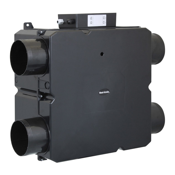
Read the following instructions in conjunction with the illustrations before commencing installation. Product Description The INTEGRA PLUS is a loft/ceiling mounted heat recovery ventilation unit for domestic and commercial applications. It is designed for connection to 150mm-diameter insulated flexible or rigid ventilation ducting. -
Page 3: Air Direction
Air Direction Intake from Outside Exhaust to Outside Extract from Rooms Supply to Rooms Exploded View of Fan unit Cover Heat Recovery Cell Extract Motor Supply Motor Base Controller Page 3 of 12... -
Page 4: Installers Guide
The unit should, for optimum drainage, be tilted by 3 degrees towards the drain side. See Fig. 3a. Ceiling mounted:. Invert the unit with the Vent-Axia logo facing down and attach the unit securely to the rafters. For optimum performance, ensure the ductwork does not turn 90deg directly off the spigots. -
Page 5: Mounting Options
Mounting Options Fig 3a. Mounted on joists CONDENSATION DRAIN (THE UNIT SHOULD SLOPE DOWNWARDS BY 3° TOWARDS THE CONDENSATE DRAIN) 8 CORE CONTROLLER CABLE Fig 3b. Ceiling mounted 8 CORE CONTROLLER CABLE CONDENSATION DRAIN (THE UNIT SHOULD SLOPE DOWNWARDS BY 3° TOWARDS THE CONDENSATE DRAIN) Fig 4. -
Page 6: Installing The Controller
Installing the Controller Controller Dimensions Dimensions of the Controller Box Installing the Controller Remove the controller from the packaging. After noting the positions of the cable connections on the unit, select a suitable installation site (allow for an extra 30mm clearance either end for cable glands. - Page 7 Setting and wiring the Controller Any power supply to the controller must be switched off before any work is done on the controller or the cover is removed. Remove the controller cover by unscrewing the 6 cover screws. 2 screws on top of unit 4 screws to side of controller (2 visible in this picture) Determine which voltages are needed to give the appropriate volumes (there is a graph in the appendix for reference).
- Page 8 Earthing Crimped The Mains cable gland must be then tightened and secured. The 2 Molex connectors from the Fan unit must then be pushed through the hole in the Controller housing and connected to the appropriate Molex connectors inside the PCB (fitting red to red and blue to blue). They are colour coded as well as polarised to aid connection.
-
Page 9: Wiring Diagrams
Wiring Diagrams Fig.1 Fig.2 Supply 220-240V 50Hz Lighting circuit Light switch INTEGRA PLUS CONTROLLER Relay COMM Lamp BOOST PURGE Switched COMM fused spur BOOST PURGE Fig.3 Fig.4 Fig.1 = Wiring via a 3 speed external switch Symbols for 3 speed switch Fig.2 = Wiring via a light switch... -
Page 10: Maintenance And Cleaning
Maintenance and Cleaning Cleaning Instructions Isolate from the mains supply before cleaning the product. The following cleaning and disinfection regime should be conducted every 6 months to maintain the efficiency and hygiene of the unit. Cleaning should be carried out by a suitably qualified person. Care should be taken when using sterilising solutions;... - Page 11 Please leave these instructions with the end user Appendix 1 Air Performance Graph INTEGRA PLUS Air performance HR300XL Air Performance Extract - - - - Supply 230V 190V 160V 130V (m³/h) Volume (l/s) 0 Page 11 of 12...
- Page 12 Tel: 0844 8560590 Fax: 01293 565169 TECHNICAL SUPPORT: Tel: 0844 8560594 Fax: 01293 532814 For details of the warranty and returns procedure please refer to www.vent-axia.com or write to Vent-Axia Ltd, Fleming Way, Crawley, RH10 9YX 438178C 1212 Page 12 of 12...
Need help?
Do you have a question about the INTEGRA PLUS and is the answer not in the manual?
Questions and answers