Table of Contents
Advertisement
Quick Links
Advertisement
Table of Contents

Related Manuals for Essilor Neksia


Summary of Contents for Essilor Neksia
- Page 1 User Manual...
-
Page 3: Table Of Contents
> C ANUAL ONTENTS ONTENTS NTRODUCTION I. F IRST STEPS WITH EKSIA 1. Descriptive diagrams 2. Connection to an edger 3. Using the tracer-centerer-blocker a. Turn on and turn off the tracer-centerer-blocker b. Using the touch screen and keypads c. Work screen II. - Page 4 > C ANUAL ONTENTS b. Block the lens IV. M ODIFYING THE LENS SHAPE 1. Menu screen 2. Modifying a shape a. Enlarging, reducing or rotating a shape b. Free-form modification c. Retouching a shape 3. Archiving / saving a shape V.
- Page 5 > C ANUAL ONTENTS ECHNICAL DATA 1. Tracer-centerer-blocker 2. Environment ENERAL INFORMATION 1. Symbols 2. Modifications 3. Declaration of conformity 4. Copyright 5. Materials and products 6. Safety instructions: 7. Electromagnetic waves LOSSARY...
-
Page 7: Introduction
• the user manual, present on the CD-ROM The screens may vary according to the edger connected to the tracer-centerer-blocker. This documentation was produced with a connection to the Neksia edger. Neksia > v1-02-14... - Page 8 > I ANUAL NTRODUCTION Neksia > v1-02-14...
-
Page 9: First Steps With Neksia
I. F IRST STEPS WITH EKSIA... -
Page 10: Descriptive Diagrams
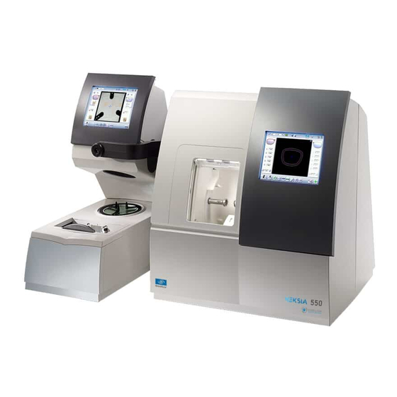
1. D ESCRIPTIVE DIAGRAMS This section contains the descriptions and list of accessories of the tracer-centerer-blocker: Screen Blocking arm Centering chamber Tripod Tracing table ON/OFF button Connectors Manufacturer plate RS232 (edger) port Barcode reader port Neksia > v1-02-14... -
Page 11: Connection To An Edger
2. C ONNECTION TO AN EDGER To connect the tracer-centerer-blocker to an edger, use the RJ45 cable (Neksia/Mr Orange edgers) or RS232 cable (Jess/Jessie /JessD/Kappa edgers) provided with the edger. For the RS232 cable, refer to the labels indicating the direction of connection. -
Page 12: Using The Tracer-Centerer-Blocker
During a prolonged period of non-use (several days), it is preferable to turn off the tracer-centerer- blocker by unplugging the mains power supply. b. Using the touch screen and keypads Using the touch screen Use the stylus on the touch screen. You can also touch the screen with your finger. Neksia > v1-02-14... - Page 13 Reset the fields • Back • Confirm • Cancel and go back to the work screen • The alphanumeric keyboard is displayed for storing, calling and searching for jobs. • & & • Job reference (alphanumeric characters) Neksia > v1-02-14...
-
Page 14: Work Screen
Settings Devices connected Active eye and information on the shape Work area Function buttons Actions available for the current screen Detailed functions For more information, consult the section Perform a trace > Tracing environment> Captioned screen. p.40) Neksia > v1-02-14... -
Page 15: Ii. T Racing
II. T RACING... -
Page 16: Tracing
Menu screen Dimensions display ◦ A: A-dimension ◦ B: B-dimension ◦ D: D-dimension ◦ E: Greater radius from the boxing center ◦ P: Perimeter Function buttons ◦ Tracing ◦ Centering Neksia > v1-02-14... - Page 17 For mechanical tracing of demo lenses, recut lenses or patterns, the tracer automatically detects the pattern holder inserted in the tracing table. New Job For more information on jobs , refer to the section Tracing > Shape management and storage & p.22) Tracing cycle initialization Neksia > v1-02-14...
-
Page 18: Jobs And Working Modes
• tracing - tracing - preparing edging - centering mode The selected work mode is shown in the information bar, to the left of the Essilor logo. You can change it in the tracer settings. Working in tracing - centering - preparing edging mode At the end of a tracing, the tracer-centerer-blocker displays the centering screen automatically then the edging preparation screen. - Page 19 You can perform several tracings in succession. • The tracings are saved under the job number that you have assigned to them. • Shape modification, edging preparation, centering and blocking are processed later. • All jobs must be saved. Neksia > v1-02-14...
-
Page 20: Displaying The Binocular View
In tracing - centering mode, the centering screen is displayed at the end of the tracing: Select then to access the tracing screen. The monocular view is displayed by default. Press to display the binocular view. Neksia > v1-02-14... - Page 21 > The binocular view is displayed. 2. Position the frame in front of the screen, against the faceplate to check its shape and centering. 3. Press to return to the monocular screen. Neksia > v1-02-14...
-
Page 22: Shape Management And Storage
Sort the jobs ◦ ◦ Reference ◦ Date ◦ Types of jobs: ◦ Drilled ◦ Asymmetric tracings ◦ Creative shapes Selected job Select the eye to be displayed in the preview Neksia > v1-02-14... - Page 23 Delete the selected job(s) Press to delete the selected job(s). A confirmation message is displayed. Search for a job by ID or by reference Rename the selected job Duplicate the selected job Call the selected shape to the work area Neksia > v1-02-14...
-
Page 24: Job List
Manufacturer, etc. Press on to confirm. > The tracing screen is displayed, the allocated ID appears in the information bar. The tracer-centerer-blocker is ready for tracing. For further information, refer to the section concerning your job type. Neksia > v1-02-14... -
Page 25: Working In Current Job Mode (Job A)
The alphanumeric keypad is displayed. For more information on entry and use of the keyboard, refer to the section First steps > Using the tracer-centerer-blocker > Using the touchscreen and keypads p.12) Press to select the ID field. & Neksia > v1-02-14... -
Page 26: Tracing A Rimmed Frame
• monocular tracing to cut only one lens of a rimmed frame Place the frame in the tracing table, between the two clamps located opposite you. Gently close the jaw to hold the frame. Neksia > v1-02-14... -
Page 27: Tracing A High-Base Frame (Option)
Put the frame in place and start the tracing When you place the frame in the tracing table, position the eye as flat as possible: the black grips which hold the eye to be traced must be in the middle of the circle. Neksia > v1-02-14... - Page 28 The numeric keypad is displayed. Enter the value of the D-dimension, then press to confirm. > Once the tracing of the first eye is finished, a message is displayed: Position the frame to trace the second eye. Neksia > v1-02-14...
- Page 29 You can also press for a few seconds on the value and change it using the numeric keypad. > The value of the curve angle is modified. Neksia > v1-02-14...
-
Page 30: Tracing A Pattern, Demo Lens Or Recut Lens
Prerequisite: for the tracer to correctly detect the horizontality of the lens, the lens must be clean and marked using the permanent felt tip marker with: • either three focimeter dots, • or a horizontal line which must not touch the edges of the lens (a space of at least 5 mm is required) Neksia > v1-02-14... - Page 31 > The numeric keypad is displayed. Enter the D-dimension value, then press to confirm. > The drilling screen is displayed. Configure the drilling settings if necessary. Neksia > v1-02-14...
-
Page 32: Mechanical Tracing
• add drilling to the shape. For more information, refer to the section Preparing a drilled job p.73) b. Mechanical tracing Detailed view of the pattern holder Front tab Neksia > v1-02-14... - Page 33 Press on the knurled knob, screwing it, until the pattern is immobilized (as for fixing a lens). > The pattern is clamped. Screwing of the knurled knob inside the tip posiblock has no functional impact on the latter. Neksia > v1-02-14...
- Page 34 (next to you - see illustration below). Check that the pattern holder does not move in the table. Tracing Press to start mechanical tracing. To interrupt tracing at any time, press > The tracer automatically detects the pattern holder. Neksia > v1-02-14...
-
Page 35: Inputting The Curve And The Frame Base After Monocular Tracing
Prerequisite: before entering the curve angle and frame base, one of the following operations must be performed: • Optical tracing of a pattern, a demo lens or a recut lens p.30) • Mechanical tracing of a pattern, demo lens or recut lens p.32) Neksia > v1-02-14... - Page 36 • the bridge of the frame superimposed on the base line. Use the buttons to align the light blue lines with the nasal and temporal ends of the circles. Neksia > v1-02-14...
- Page 37 The value is displayed in red. Use the buttons to modify the frame base value. You can also press for a few seconds on the value and change it using the digital keyboard. Press on to confirm. Neksia > v1-02-14...
- Page 38 > II. T ANUAL RACING Neksia > v1-02-14...
-
Page 39: Centering
III. C ENTERING... -
Page 40: Centering Environment
Job call p.42) • Using the tripods p.43) • Centering modes p.43) • Centering help p.44) a. Menu screen Centering screen indicator Blocking mode ◦ Blocking in the boxing center & ◦ Blocking in the optical center Neksia > v1-02-14... - Page 41 Entering the curve angle and frame base Lens type selection ◦ Single vision lens & ◦ Progressive lens & ◦ Bifocal lens & ◦ Executive lens & ◦ Mid-distance lens & Value modification Enables you to reduce or increase the previously selected value. Neksia > v1-02-14...
-
Page 42: Call A Shape (If The Connection To Tess Is Activated)
> A warning message is displayed. • Press to replace the job displayed by the job called. • Press to cancel: the job is not transmitted to the tracer. > The shape is displayed in the centering screen. Neksia > v1-02-14... -
Page 43: Using The Tripods
You can adjust the spacing of the studs to ensure better lens stability. ITH THE STANDARD TRIPOD ITH THE RECUT LENS TRIPOD d. Centering modes The centering modes available depend on the type of lens selected. Always refer to the specific procedure for your type of lens. Neksia > v1-02-14... -
Page 44: Centering Help
Prerequisite: micro-engravings must be re-marked with the felt-tip pen. The diameter of the dots must be between 0.5 and 1.5 mm. We advise you to use the white felt tip marker supplied with the tracer-centerer-blocker to mark the lens. Neksia > v1-02-14... - Page 45 Enter the half PD and pupillary height. > The target moves. Ensure that the tripod is within the centering chamber. Use the recut lens tripod (option) for a high base lens, a recut lens or a decentered lens (option). Neksia > v1-02-14...
- Page 46 > The indicators are displayed in green. > The lens is centered and ready to be blocked. Three focimeter dots Micro-engravings To carry out lens blocking, refer to the section Lens Centrering > Blocking a lens p.61) Neksia > v1-02-14...
-
Page 47: Centering A Progressive Lens
• Remark the micro-engravings with the marker; the points must have a diameter ranging between 0.5 and 1.5 mm. We advise you to use the white felt tip marker supplied with the tracer-centerer-blocker to mark the lens. Neksia > v1-02-14... - Page 48 Enter the half PD and pupillary height. > The target moves. Ensure that the tripod is within the centering chamber. Use the recut lens tripod (option) for a high base lens, a recut lens or a decentered lens (option). Neksia > v1-02-14...
- Page 49 • aligned on the line corresponding to the PRP of the lens. The PRP value of Essilor progressive lenses is 4 mm. This may vary depending on the manufacturer of the lenses. > The lens is centered and ready to be blocked.
-
Page 50: Centering A Lens Using Manufacturer Markings
The lens must at least have the following markings: Far vision mark Centering marks Centering the lens Press to select the type of progressive lens. > The centering target is displayed: Enter the half PD and pupillary height. > The target moves. Neksia > v1-02-14... - Page 51 Perfectly centered in the centering cross, • Parallel with the horizontal lines. > The lens is now centered and ready for blocking. To carry out lens blocking, refer to the section Lens Centrering > Blocking a lens p.61) Neksia > v1-02-14...
-
Page 52: Centering Bifocal / Trifocal Lenses
This section describes the centering procedure for a bifocal or trifocal lens with a straight, curved or round & segment. Description of the centering target Centering cross (orange cross) and the boxing center of the shape (blue cross) Near vision mark Centering marks Neksia > v1-02-14... - Page 53 The target moves. Ensure that the tripod is within the centering chamber. Use the recut lens tripod (option) for a high base lens, a recut lens or a decentered lens (option). Position the lens on the tripod. Neksia > v1-02-14...
-
Page 54: Centering An Executive Lens
Prerequisite: the lens must be marked using a focimeter. The three focimeter dots must be: • aligned, • at the same distance from the central dot, • 0.5 to 1.5 mm in diameter. Description of the centering target Centering mark Neksia > v1-02-14... - Page 55 The target moves. Ensure that the tripod is within the centering chamber. Use the recut lens tripod (option) for a high base lens, a recut lens or a decentered lens (option). Position the lens on the tripod. Neksia > v1-02-14...
-
Page 56: Centering A Mid-Distance Lens
Description of the centering target Centering cross (orange cross) and boxing center of the shape (blue cross) Centering graduated marks The horizontal line is situated at 6mm enabling you to measure the PRP distance. Neksia > v1-02-14... -
Page 57: Centering A Lens Using Re-Marked Micro-Engravings
Centering the lens Press to select the type of mid-distance lens. > The centering target is displayed: Enter the half PD and the frame height. > The target moves. Ensure that the tripod is within the centering chamber. Neksia > v1-02-14... - Page 58 • aligned on the line corresponding to the PRP of the lens. The PRP value of Essilor mid-distance lenses is 6 mm. This may vary depending on the manufacturer of the lenses. > The lens is centered and ready to be blocked.
-
Page 59: Centering A Lens Using Manufacturer Markings
The lens must at least have the following markings: Centering cross Centering marks Centering the lens Press to select the type of mid-distance lens. > The centering target is displayed: Enter the half PD and the frame height. Neksia > v1-02-14... - Page 60 Perfectly centered in the centering cross, • Parallel with the horizontal lines. > The lens is now centered and ready for blocking. To carry out lens blocking, refer to the section Lens Centrering > Blocking a lens p.61) Neksia > v1-02-14...
-
Page 61: Centering For A High-Base Frame
Centering an executive lens p.54) • Centering a mid-distance lens p.56) 8. B LOCKING A LENS This section describes the procedures for lens blocking depending on the selected option: • Blocking preparation p.62) • Blocking with the automatic arm p.63) Neksia > v1-02-14... -
Page 62: Preparing Blocking
18x14 mm posiblock Magnet The posiblocks and their corresponding pads are supplied with the edger. • Always use Essilor pads: they are specially designed to ensure the performance of your machine for quality jobs. • The pads are non re-usable. -
Page 63: Block The Lens
The adjustments made to the PD, pupillary height, type of lens and type of centering are displayed by default for the second lens. Center and block the second lens. > The edging preparation screen is displayed automatically. Consult the chapter Preparing lens edging p.87) Neksia > v1-02-14... - Page 64 > III. C ANUAL ENTERING Neksia > v1-02-14...
-
Page 65: Modifying The Lens Shape
IV. M ODIFYING THE LENS SHAPE... -
Page 66: Menu Screen
(yellow) Limit of the drilling zone ◦ (red) Non-machinable shape ◦ (blue) Reference drilling points Binocular view Half PD and pupillary height Active eye The selected eye has an orange frame around it. D-dimension modification A-dimension modification Neksia > v1-02-14... -
Page 67: Modifying A Shape
Both lenses are modified simultaneously. a. Enlarging, reducing or rotating a shape The side panel on the right of the screen enables you to: • Modifying each dimension or half-dimension separately • Modifier the size of a shape as a whole Neksia > v1-02-14... - Page 68 You can also press for a few seconds on the corresponding value to display the numeric keypad: enter a new value and press to confirm. > The shape is modified. > The original shape is displayed in light red. Neksia > v1-02-14...
- Page 69 • Press once to cancel the last modification made to the shape. • Press twice consecutively to return to the original shape. Once the shape is modified, press to save and go back to the centering screen. Neksia > v1-02-14...
-
Page 70: Free-Form Modification
• Press once to cancel the last modification made to the shape. • Press twice consecutively to return to the original shape. Once the shape is modified, press to save and go back to the centering screen. Neksia > v1-02-14... -
Page 71: Retouching A Shape
The types of retouch available vary according to the size of the selected area. • Retouch to create a straight line. • Retouch to create a curve. • Retouch to create an angle. > The selected area is retouched. > The original shape is displayed in light red. Neksia > v1-02-14... -
Page 72: Archiving / Saving A Shape
You can also give it a different ID. Enter a reference for the shape to be saved. Press on to confirm. > The shape is archived in a new job with a new ID and is displayed in the shape modification screen. Neksia > v1-02-14... -
Page 73: Preparing A Drilled Job
V. P REPARING A DRILLED JOB... - Page 74 • Neksia RC • Neksia Drill (with drilling function). Photo mode To prepare a drilled job from a mechanically traced shape, proceed as follows: On the centering screen, position the demo lens within the centering chamber so that the shape and the demo lens coincide as far as possible.
-
Page 75: Legend Screen
For more information on drilling settings, consult the section Preparing a drilling job > Configuring a drilling point p.78) 1. L EGEND SCREEN The drilling screen is accessible: • from the centering screen (press briefly on • from the edging settings screen (long press on Neksia > v1-02-14... - Page 76 X and Y coordinates in relation to the boxing center of the shape. & ◦ Distance between the center of the drill-hole entrance point and the edge of the lens. ◦ X and Y coordinates in relation to the reference drilling point. Neksia > v1-02-14...
- Page 77 Archive the shape and create a new job based on the job displayed Back to the centering screen ◦ Press to save the changes and return to the centering screen. ◦ Press to return to the centering screen without saving the changes. Neksia > v1-02-14...
-
Page 78: Configuring A Drilling Point
The drilling coordinates are displayed on the right of the work screen; Press to copy the drilling points from the nasal area to the temporal area and vice-versa. On the tracer-centerer-blocker, you can configure up to 6 drilling points per side (nasal and temporal) of a shape. Neksia > v1-02-14... -
Page 79: Delete One Drilling Point
> The numeric keypad is displayed. You can also use the buttons to decrease or increase the selected value. Enter the new value of the parameter and press to confirm. > The drilling point has been modified. Neksia > v1-02-14... -
Page 80: Adjusting The Position Of A Drilling Point
The drilling coordinates are those of its entrance drill-hole. • For a drill-hole, it is the center. • For a slot and a notch, the entrance point is always on the side which is furthest away from the edge of the lens: Neksia > v1-02-14... - Page 81 If you need to modify several drilling points simultaneously, you can group them together provided they are on the same side of the shape (nasal side / temporal side). By default, the symbol is displayed: each drilling point can be modified individually. Neksia > v1-02-14...
- Page 82 You can position each drilling point in relation to the reference drilling point by modifying the values in the columns: • X coordinates in relation to the reference drilling point • Y coordinates in relation to the reference drilling point Neksia > v1-02-14...
-
Page 83: Drilling Models
Select the desired list. > The drilled jobs in the selected list are displayed. Select the desired job as a drilling model. > The model is displayed in the preview. Press to confirm import of the model. Neksia > v1-02-14... -
Page 84: Saving A Model
The distance from reference drilling points in relation to the edge of the lens (other drillings, in relation to reference drilling) Press to save the job and its drilling points. > The job-creation alphanumeric keypad is displayed. Neksia > v1-02-14... - Page 85 The new job with the new ID is displayed on the drilling screen. Press to return to the centering screen. You can go back to the previous job via the shape management screen if it has an ID. Neksia > v1-02-14...
- Page 86 > V. P ANUAL REPARING A DRILLED JOB Neksia > v1-02-14...
-
Page 87: Preparing Lens Edging
VI. P REPARING LENS EDGING... -
Page 88: Menu Screen
Medium/High index plastic lens - index > 1.5 ◦ Trivex lens ◦ Glass lens ◦ Lens material to be defined on the edger The configuration of the edging cycles depends on the type of material. An incorrect choice may result in material damage. Neksia > v1-02-14... - Page 89 ◦ Thin chamfer front surface ◦ Thick chamfer front surface ◦ No chamfering ◦ Chamfer to be defined on the edger Rear surface chamfering ◦ Thin chamfer front surface ◦ Thick chamfer front surface ◦ No chamfering Neksia > v1-02-14...
-
Page 90: Edging Configuration
> When you call the shape from the edger, its edging settings will be automatically recovered. Neksia > v1-02-14... - Page 91 VII. T RACER CENTERER BLOCKER CONFIGURATION...
-
Page 92: Tracer Centerer Blocker Configuration
Date Use the arrows to set the date. Type of date display Select the type of display out of the available formats. Language Select the flag corresponding to your language. Other languages Neksia > v1-02-14... -
Page 93: Options
Screen example: Optical tracing activated not activated by default. option available until the date indicated Job memory activated activated by default. Connection to Mr Orange activated not activated by default. High-base tracing and remote lens edging not activated Neksia > v1-02-14... -
Page 94: Connections
If necessary, first activate the connection to the Tess tracer via the customization screen. To do this, refer to the section Configuring the tracer> Customizing the tracer-centerer-blocker > Work modes and display precision p.97) To access the configuration menu for the connection from the work screen of your tracer-centerer-blocker, select > > Neksia > v1-02-14... -
Page 95: Screensaver And Brightness Of The Work Area
Screensaver and brightness of the work area This menu is used to configure a screensaver and the brightness of the work area. To access this menu from your work screen, select > > Neksia > v1-02-14... -
Page 96: Customize The Tracer-Centerer-Blocker
This section will enable you to customize the tracer according to your requirements: • Customising the working modes and display precision p.97) • Choosing a decentration mode p.98) • Customising the action bar p.99) • Adjusting the brightness p.101) Neksia > v1-02-14... -
Page 97: Working Modes And Display Precision
Select the desired step for the shape modification. PD and pupillary height Select the desired step for input of the PD and pupillary height. Working mode Select the default working mode: ◦ Tracing-tracing ◦ Tracing - centering Neksia > v1-02-14... -
Page 98: Decentration Mode
Decentration mode This menu enables you to select a default input mode for decentration data. To access this menu from your work screen, select > > The following screen is displayed: Neksia > v1-02-14... -
Page 99: Action Bar
• disable options you do not require so they are no longer displayed in the job options. To access the customization menu of the action bar from your work screen, select > > Neksia > v1-02-14... - Page 100 Metal frame ◦ Plastic frame ◦ Optyl frame, for particularly flexible frames ◦ Automatic detection Tracing mode ◦ Pattern ◦ Demo lens / Recut lens Type of lens ◦ Single vision lens ◦ Progressive lens ◦ Bifocal lens Neksia > v1-02-14...
-
Page 101: Brightness
You can adjust the default brightness of the work area and/or the touch screen in order to improve your view of the lens to be centered. To access the brightness customization menu from your work screen, select > > The following screen is displayed: Overview of the work area Neksia > v1-02-14... -
Page 102: Restoring The Factory Settings
At the bottom right of certain settings screens of the tracer-centerer-blocker, the button can be used to restore the factory parameters of the page. • Press to cancel and go back to the settings screen. • Press to confirm reinitialization. Neksia > v1-02-14... -
Page 103: Aintenance Servicing
VIII. M & AINTENANCE SERVICING... -
Page 104: Carrying Out The Autotests
The result is displayed on the right of the icon of the autotest carried out: • The equipment is operational. • A malfunction has been detected, a description is shown in the message box at the bottom of the screen. Neksia > v1-02-14... -
Page 105: Check And Calibrate (Remote Lens Edging Option)
Calibrate the touch screen p.110) a. Check and calibrate the tracing table (option) If you encounter mounting problems, you can check the calibration of the tracing table. From the work screen of your tracer, select > > Neksia > v1-02-14... - Page 106 If none of the references match that marked on the gauge, contact the technical department. Select Insert the pattern gauge in the tracing table. Press to start the test. Wait: a timer is displayed for a few minutes. Neksia > v1-02-14...
- Page 107 Wait: a timer is displayed for a few minutes. > : The first calibration phase is finished. > The image of the frame gauge is displayed: Insert the frame gauge in the tracing table. Close the jaws. Neksia > v1-02-14...
-
Page 108: Check And Calibrate The Blocking Arm
If you encounter problems with centering or blocking, you can check the calibration of the centering chamber and blocking arm. If the device has been moved, it is recommended to check the arm calibration. From the work screen, select > > Neksia > v1-02-14... - Page 109 Prerequisite: Make sure the blocking head is empty before starting the check or calibration. Select the desired option. Press to start the cycle. > A warning message is displayed. Remove any objects from within the centering chamber. Press on to confirm. > The procedure was successful Neksia > v1-02-14...
-
Page 110: Calibrate The Touch Screen
The settings menu is displayed automatically once the calibration is finished. Press to return to the work screen. 3. M AKE A BACKUP OF THE JOBS AND DISPLAY CONFIGURATION Connect the backup USB key to the tracer. From the work screen, select > Neksia > v1-02-14... - Page 111 Press to start the operation. > Once the backup is performed, a file is created on the backup key: Product number L20XXX - Product serial number XXXXXX- Optician- Date “XX/XX/XXXX”-Time "XXhXXmXXs" Example: Neksia > v1-02-14...
- Page 112 To import on the tracer: • a previously created backup • the jobs and configuration of the tracer or another Neksia tracer, • calibration data of the tracing table calibration gauge (option). Connect the backup USB key to the tracer.
-
Page 113: Statistics And Technical History
Total number of tracings ◦ Asymmetric binocular tracing & ◦ Symmetric binocular tracing & ◦ Right-eye monocular tracing ◦ Left-eye monocular tracing ◦ High-base frame tracing (option) ◦ Mechanical tracing (patterns, demo lenses or recut lenses) Traced frame materials Neksia > v1-02-14... -
Page 114: Technical Log And Errors
Select the cycle counter to reset to zero. b. Press to reset it to zero. b. Technical log and errors From the work screen, select > > to access the list of error messages. The following screen is displayed: Partial counter Neksia > v1-02-14... -
Page 115: Maintain And Clean The Tracer-Centerer-Blocker
A dirty or scratched glass may cause tracing and centering faults. It must be replaced by a technician. Take care of it and clean it regularly using a soft, dry cloth. Never pour liquid on the glass pane of the centering chamber. Neksia > v1-02-14... - Page 116 > VIII. M & ANUAL AINTENANCE SERVICING Neksia > v1-02-14...
-
Page 117: Technical Data
ECHNICAL DATA... -
Page 118: Tracer-Centerer-Blocker
Communication protocol: OMA (ISO 16284) Integrated auto-maintenance functions (self-calibration, autotests) Dimensions: L 280 mm, P 520 mm, H 610 mm Size of colour touch screen: 8.4 inches Weight: 18.2 kg External power supply: 100-240 V - 50-60 Hz, Neksia > v1-02-14... -
Page 119: Environment
The back of your machine must be at least 20 cm away from a wall. This machine is neither adapted nor intended to operate in an environment where there is a risk of explosion. Neksia > v1-02-14... - Page 120 > T ANUAL ECHNICAL DATA Neksia > v1-02-14...
-
Page 121: General Information
ENERAL INFORMATION... -
Page 122: Symbols
Essilor cannot be held responsible for any malfunction or loss of data resulting from such errors or omissions. -
Page 123: Copyright
(2) must accept interference from external sources, notably that liable to cause malfunctions. In accordance with the requirements of FCC rules, any modification made to this equipment which is not expressly approved by ESSILOR INTERNATIONAL would nullify the user's right to use this device. -
Page 124: Electromagnetic Waves
The products have been designed to withstand interference and operate despite its presence and the possibility of micro-outages on the network. However, if these malfunctions are too serious and abnormal, the machine cannot be guaranteed to operate normally. Neksia > v1-02-14... -
Page 125: Glossary
LOSSARY... - Page 126 • separation line present on the rear surface of the lens • Example of lenses of this type: Telex lenses The job identifier, or ID, consists of alphanumeric characters. It is unique. Neksia > v1-02-14...
- Page 127 The indices vary according to the materials used for the lenses: • Plastic lens: 1.5 • Polycarbonate lens: 1.59 • Medium or High Index lens: > 1.5 • Trivex™ lens: 1.5 to 1.6 • Glass lens: 1.5 to 1.9 Neksia > v1-02-14...
- Page 128 • the lower part of the lens is used for near vision. RIPOD Tripod to be used for centering all types of lens, except recut lenses. Neksia > v1-02-14...
- Page 130 Essilor Instruments USA 8600 W. Catalpa Avenue, Suite 703 Chicago, IL 60656 Phone: 855.393.4647 Email: info@essilorinstrumentsusa.com www.essilorinstrumentsusa.com...
Need help?
Do you have a question about the Neksia and is the answer not in the manual?
Questions and answers