
Related Manuals for Wellav DMP900


Summary of Contents for Wellav DMP900
- Page 1 DMP900 Digital Media Platform User Guide V2.2-N DVBCommunity - cообщество профессионалов ЦТВ https://dvbcommunity.ru/...
- Page 2 DMP900 User Guide Revision History Date Version Description Author 1/1/2011 First Draft 12/27/2012 1.06 New Module Introduction Added 4/9/2013 1.07 New Module Introduction Added 1/15/2015 1.10 New Module Introduction Added 8/30/2016 2.0-N New Web User Interface 12/5/2016 2.1-N Add Power specification, NIT NOTE, EN4SC-xM2Axx 6/28/2017 2.2-N...
- Page 3 DMP900 User Guide Safety Instructions Read these instructions Keep these instructions Follow all instructions Heed all warnings Do not use this unit near water. Only use a damp cloth to clean chassis Do not install near any heat sources such as radiators, heat registers, stoves, or other apparatus (including amplifiers) that produce heat ...
- Page 4 DMP900 User Guide SAFETY PRECAUTIONS There is always a danger present when using electronic equipment. Unexpected high voltages can be present at unusual locations in defective equipment and signal distribution systems. Become familiar with the equipment that you are working with and observe the following safety precautions.
-
Page 5: Table Of Contents
DMP900 User Guide Contents PART 1 PANEL OVERVIEW · · · · · · · · · · · · · · · · · · · · · · · · · · · · · · · · · · · · · · · · · · · · · · · · · · · · · · · · · · · · · · · · · · · · · · · · · · · · · · · · · · · · · · · · · · · · · · · · · · · · · · · · · · · · · · · · · · · · · · · · · · · · · · · · · · · · · · · · · · · · · 1 1.1 F... - Page 6 DMP900 User Guide 4.1.11 OFDM · · · · · · · · · · · · · · · · · · · · · · · · · · · · · · · · · · · · · · · · · · · · · · · · · · · · · · · · · · · · · · · · · · · · · · · · · · · · · · · · · · · · · · · · · · · · · · · · · · · · · · · · · · · · · · · · · · · · · · · · · · · · · · · · · · · · · · · · · · · · · · · · · · · · · · · · · · · · · · 41 4.1.12 8VSBM ·...
-
Page 7: Part 1 Panel Overview
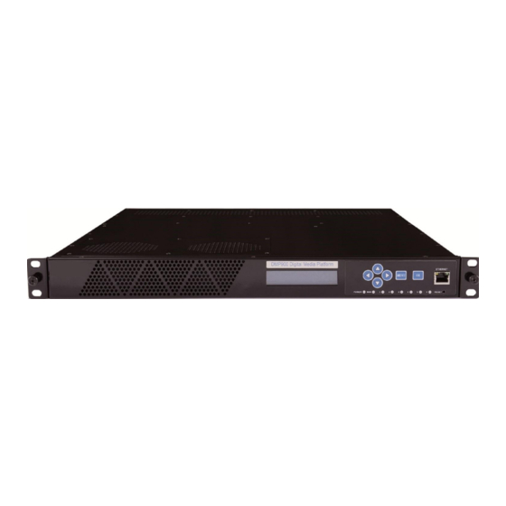
1.1 Front Panel DMP900 is a powerful, platform-based and multipurpose video-processing product. Equipped with six hot-swappable modules, DMP900 supports almost any video delivery requirement with any combination of receiving, de-scrambling, transcoding, re-multiplexing/grooming, scrambling, modulating and IP/ASI turn around for service providers. -
Page 8: Rear Panel
The DMP00 is cooled via forced induction through the front of the unit and exhausted through the slots in the rear of the chassis. The DMP900 is equipped with a temperature controlled status indicator. If the temperature inside the chassis exceeds 50° C (the default alarm threshold) the mainboard status indicator will be flashing red on the front panel. -
Page 9: Part 2 Installation
Part 2 Installation 2.1 Rack Installation The DMP900 is designed to be mounted in a standard 19” rack. It takes 1RU of rack space. To install it into a rack, please use the following steps: 1. Determine the desired position in the rack for the DMP00. Make sure that the air intake on the top of the unit and the exhausts on the back of the unit will not be blocked. -
Page 10: Configuring Network Via Front Panel
Version Mainboard Version Sub board/Slot Version To configure DMP900 network, use the following steps: 1. Press MENU button to enter Main Menu. 2. Use Up, Down, OK button to navigate and enter submenus. 3. In order to change the addresses, press OK button to enter edit mode. When a short line appears under editable digit, press Up or Down button to change the digit, then press Left or Right button to edit next digit. -
Page 11: Part 3 Web Gui
CAT5 straight-through cables. If you do not have a switch, you can connect the computer directly to DMP900’s management port. Set the IP address of the laptop/computer in the same network with the DMP900 management IP address. For example, you can set the computer’s IP address to 192.168.1.98. ... -
Page 12: Logging Into The Web Gui
DMP900 User Guide 3.1.2 Logging into the Web GUI Type the DMP management IP address into the URL field of any recommended browser (IE8 or above, Firefox, and Google Chrome) to access the logon page. By default, the admin user account is admin with password admin. -
Page 13: Dropdown Menu Overview
Menu Module Configuration is where you set input and output parameters for each board. Menu Service Configuration is where to distribute services. Menu Equipment Configuration includes the basic settings for a DMP900 unit. 3.1.4 Service Configuration Service Configuration page, see the following image, is the main page to distribute input and output services. - Page 14 Click Apply buttons every time you complete the settings in these pages. Click Save to save all the configurations into the flash memory. Only in this way will the DMP900 be able to restore all the configurations after power recycling.
-
Page 15: Basic Operations
Click Clear Power Alarm to clear the alarm for power supply. If you change the IP address of the DMP900 in System page and click Apply, this unit will restart itself to activate the new IP address. -
Page 16: Configuring Input
DMP900 User Guide 3.2.2 Configuring Input Before configuring the input, please plug in an input cable with valid signals. Steps to configure ASI input: 1. Go to Module configuration > ASI, set Port 1 and Port 2 as input ports. Click Apply before you go to the next step. - Page 17 DMP900 User Guide Batch Scan is really a convenient function especially used to search multiple TSIP input channels. So you do not have to do it one by one. Note before you use this function, please go to Status > TSIP and verify all the input channels you are going to batch scan present input bitrates.
-
Page 18: Configuring Output
DMP900 User Guide 3.2.3 Configuring Output Verify the output ports are enabled in Module Configuration. Use the following two ways to create output TS: Drag TS to TS Click an input TS; drag and drop it to an output TS. Click Apply. Click Save if necessary. See the following Image, there is a TS coming from Board6 ASI input, and a TS is to be created in Board4 TSIP output port. - Page 19 DMP900 User Guide Go to Status > TSIP (64I32O) to verify the Effective Bitrate in the corresponding output channel. Go to Module Configuration > TSIP (64I32O) > Output*Channel (1-16). See the following image. Set the Constant Rate 2 Mbps higher than the output Effective Bitrate you to avoid overflow. For example, if the Effective Bitrate of ASI output TS1 is 3.822 Mbps, set Constant Rate 6 Mbps.
-
Page 20: Delete An Output Ts/Program/Pid
DMP900 User Guide EMM and Other PIDs (EIT, SDT, TDT and other PIDs) can be output by drag-and-drop procedures. 3.2.4 Delete an Output TS/Program/PID Move the cursor to a TS, Program or PID until a red icon ( ) appears. Click the red icon to delete the service or PID. -
Page 21: Version Information/Upgrade
Click Browse to select the software. Then click Upgrade to start update process. If it is a mainboard upgrade, DMP900 will reboot itself after upgrade is finished. If it is module upgrade, Go to Module Configuration and click Reboot to load the module again. -
Page 22: Import/Export Configuration
DMP900 User Guide License page is where to check and update licenses. Note slot 0 refers to the Mainboard. Updating License 1. Click Browse to select a license file. 2. Click the circle to select a slot number, then click Export License to save the license in the computer. -
Page 23: Login User Management
In that case, you will lose the configuration of this unit. 3.2.9 Log Log records the operations and activities of a DMP900. We may request an exported log file from user for troubleshooting or other use. -
Page 24: Advanced Operations
DMP900 User Guide 3.3 Advanced Operations 3.3.1 Edit Output TS Right-click any output TS and select Edit TS Info. When the Output TS Standard in the System page is DVB, you have the following editable items. Name Range Name Range... -
Page 25: Edit Service Information For Dvb Output
DMP900 User Guide PID 8191 is taken as the PID for null (stuffing) packets. When the Output TS Standard in the System page is ATSC, you have the following editable items. Name Range Name Range Max 32 letters 32~8190 Service Name... - Page 26 DMP900 User Guide Add Network Information Table (NIT) See the following image. Board3 [QAM A/C] is streaming output TS1, TS2 and TS3. Original Network ID is 1. TS1 ID is 1, and TS2 with ID 2, TS3 ID 3. TS1 frequency is 474000 KHz, and TS2 482000 KHz, TS3 490000 KHz.
- Page 27 DMP900 User Guide 3. Right-click transport_descriptors in transport_stream_id:1 to add Cable Descriptor for TS1. 4. Repeat step 2 to add TS2 and TS3. Repeat step 3 to add cable descriptors for these two TS’. 5. Click Apply, and go to Service Configuration page, click Apply again.
- Page 28 DMP900 User Guide Add Logical Channel Number (LCN) LCN is used to sequence the channels in the Set Top Box. See the following image, we have a NIT tree with Cable Descriptors added in transport_stream_id:1, transport_stream_id:2, transport_stream_id:3. TS1 with Cable Descriptor...
- Page 29 DMP900 User Guide 2. Select Board1 [QAM (A/C)] Port1 TS1 by clicking the circle in front of it. Then CCTV2 and CCTV7 in TS1 will be in Services on the right side. Click in front of CCTV2 (service ID 302) and CCTV7 (service ID 303), they will be added to LCN edit list.
- Page 30 DMP900 User Guide 3. Check the LCN descriptors of CCTV2 and CCTV7 that you configured. 4. Right-click transport_descriptors under transport_stream_id:2, then select Add LCN Description to enter edit page. Select Board1 [QAM (A/C)] Port1 TS2 add LCN for CCTV10 (service ID 304) and CCTV10 (service ID 305). Click Add and Exit.
- Page 31 DMP900 User Guide 5. Repeat step 4 to add LCN for CCTV12 and CCTV15 under transport_stream_id:3. Once you have added LCN for these 6 services, click Apply in the following page. 6. Go to Service Configuration. Click Apply and Save.
-
Page 32: Upgrading Set Top Box Through Ota
DMP900 User Guide 3.3.3 Upgrading Set Top Box through OTA To update the software for a number of STB’s, use the following steps: 1. Feed the update stream to SMP by the embedded ASI or IP port. 2. Drag the update PID to QAM output port. See the following image, an update stream is taken as other PID 8001 in SMP. -
Page 33: Part 4 Module Configuration
DMP900 User Guide Part 4 Module Configuration 4.1 Input and Output Modules 4.1.1 TSIP TSIP is short for TS over IP. There two Gigabit RJ45 ports and two SFP (Small Form-factor Pluggable) ports on this module. The leftmost RJ45 port and the left SFP port are main I/O ports. - Page 34 DMP900 User Guide Module Configuration > TSIP (64I32O) > Setup Name Range Name Range 192168.1.34 Auto IP Address Speed Mode Subnet Mask 255.255.255.0 100M-Duplex 192.168.1.1 100M-Half Gateway 1000M-Half 1000M-Duplex V1, V2, V3 Off, On IGMP Version Enable Input IGEM Auto Report...
- Page 35 DMP900 User Guide Module Configuration > TSIP (64I32O) > Output Enable output TS channel. Configure multicast destination IP address, source port, and protocol. The Constant Rate should be about 2 Mbps higher than the Effective Bitrate listed in the Status > TSIP (64I32O) menu. In that case, the bitrate of inserted null packets will be around 2 DVBCommunity - cообщество...
- Page 36 DMP900 User Guide Mbps. Better not enable unemployed channels, since the enabled channels without services still output null packets at Constant Bitrate. Select Advanced Setting to configure backup port. The backup feature is available only when the main channels are transferring services.
- Page 37 DMP900 User Guide Module Configuration > TSIP (64I32O) > Output > FEC Module Configuration > TSIP (64I32O) > Output > Batch Set Batch Set is an efficient feature to Enable/Disable output ports with consecutive IP addresses. DVBCommunity - cообщество профессионалов ЦТВ...
-
Page 38: Tsip
DMP900 User Guide 4.1.2 TSIP+ TSIP+ is an enhanced TSIP module with extra memory card which supports more TS channels and can adjust the PCR better. You may assign different IP address to the main port and backup port. Its configuration pages are similar to TSIP. Please refer to chapter 4.1.1. -
Page 39: Asi
DMP900 User Guide 4.1.3 ASI ASI is a 4-channel ASI I/O module. Each ASI port can be set as either input port or output port separately. Module configuration > ASI Name Range Description Input, Output Select to determine the port to be input or output. -
Page 40: Ipasi
DMP900 User Guide 4.1.4 IPASI IPASI module is a combination of TSIP and ASI. The leftmost RJ45 port is an I/O port, and the rightmost RJ45 port only provides backup output. The two ASI ports can be set as either input or output port separately. - Page 41 DMP900 User Guide Module Configuration > DVBC Name Range Frequency (KHz) 48000~870000 Symbol Rate (KSym/s) 3000~7000 Constellation QAM16/32/64/128/256 Lock Status Lock/Un-lock Status > DVBC DVBCommunity - cообщество профессионалов ЦТВ https://dvbcommunity.ru/...
-
Page 42: Dvbs2
DMP900 User Guide 4.1.6 DVBS2 DVBS2 is a 4-channel DVBS2 receiving module. Module Configuration > DVBS2 (V2) Name Range Description 4CH Mode(Normal) 4CH Mode: QPSK, 8PSK Mode 2CH Mode(Advanced) 2CH Mode: QPSK, 8PSK, 16APSK, 32 APSK. Symbol Rate (Ksym/s) 1000~45000... -
Page 43: Dvbt2
DMP900 User Guide Dual Band Band Selection Auto Forced Low Forced High Bias Disable/Enable Available in Port2 and Port4 Polarization 13V (V) Vertical 18V (H) Horizontal Lock/Un-lock To indicate the input is locked or not. Lock Status Contact service provider for input information or visit www.lyngsat.com... -
Page 44: 8Vsb
DMP900 User Guide Name Range Description Tuner Mode DVB-T DVB-T: QPSK, 16/64QAM DVB-T2 DVB-T2: QPSK, 16/64/256QAM Frequency(KHz) 48000~862000 Bandwidth 6M, 7M, 8M Depends on the standard in your country. A, B Available when Tuner Mode is DVB-T2. PLP Mode PLP ID Available when PLP Mode is B. -
Page 45: Qam
DMP900 User Guide Name Range Description Channel 57~803MHz Refer to American ATSC (8-VSB) Channel List 4.1.9 QAM QAM module supports modulating 8 adjacent channels. The left connector is for local monitoring. Module Configuration > QAM DVBCommunity - cообщество профессионалов ЦТВ... -
Page 46: Iqam
DMP900 User Guide Name Range Name Range RF Level(dBuV) 90~106 Enable Disable, Enable Bandwidth 6M, 7M, 8M Frequency (KHz) 47000~862000 Symbol Rate (KBaud) 4400~6956 Constellation QAM64/128/256 Spectrum Shaping Disable, Enable Max Rate (Mbit) Automatically calculated 4.1.10 IQAM IQAM module supports modulating 16 non- adjacent channels. -
Page 47: Ofdm
DMP900 User Guide 4.1.11 OFDM OFDM is a 4 channel modulating module. The left connector is for local monitoring. Module Configuration > OFDM Name Range Name Range Bandwidth 6M, 7M, 8M Guard Interval 1/4, 1/8, 1/16, 1/32 RF Level(dBuV) 90~109... -
Page 48: 8Vsbm
DMP900 User Guide 4.1.12 8VSBM 8VSBM is compliant with the modulation method used for broadcast in the ATSC digital television standard. Module Configuration > ATSCM Name Range Description 80~107 dB RF level -27~0 dBm Spectrum Shaping Disable, Enable OTA, STD, IRC, HRC... -
Page 49: Hdmi/Sdi Decoder
DMP900 User Guide 4.1.13 HDMI/SDI Decoder HDMI/SDI Decoder supports decoding 2 programs in two HDMI ports and two SDI ports. Module Configuration > HDMI/SDI Decoder Name Range Name Range Aspect Ratio Automatic Output Resolution 1920x1080_50i/60p/59.94p/ Conversion 4:3 Letterbox 59.94i/60i/30p/29.97p/24p 4:3 Pan and Scan 1280x720_60p/50p/59.94p... -
Page 50: Asi-Switch
DMP900 User Guide 4.1.14 ASI-Switch ASI-Switch is a 3in2out board for ASI input redundancy application. The three ports on the right are primary, secondary (it could be a copy of the main), and fail-safe input. The two ports on the left are both output 1 and output 2 interfaces. - Page 51 DMP900 User Guide Some options in Port automatic switch settings: Automatic switch mode Use Primary program first, this module will activate switch function. Select Switch Lock to disable this feature. Min/Max total bitrate of primary, Configure Minimum and Maximum rates to define the secondary and fail-safe port normal rate ranges for the input ports.
- Page 52 DMP900 User Guide If you choose Program-level for Switch level settings, as you can see in the following image, you will need to configure Program-switch condition selection and Program Setup. Module Configuration > SWITCH > Output ASI Out 1 bitrate Configure the constant bitrate for the output ASI port 1.
-
Page 53: Ds3
DMP900 User Guide 4.1.15 DS3 DS3 is a 4-channel input/output module for SDH/PDH transmission network. Module Configuration > DS3 Name Range Description Input, Output Configure a DS3 port to be input or output Type Protocol One, Two, Three, Four DS3 interface protocol Disable, Enable DVBCommunity - cообщество... -
Page 54: Isdbt
DMP900 User Guide 4.1.16 ISDBT ISDBT is a 4-channel receiving module that fully complies with ISDBT standard. Module Configuration > ISDBT Name Range Description Frequency (KHz) 48000~862000 6M, 7M, 8M Bandwidth DVBCommunity - cообщество профессионалов ЦТВ https://dvbcommunity.ru/... -
Page 55: En4Av-4M2B
DMP900 User Guide 4.2 Encoding Modules 4.2.1 EN4AV-4M2B EN4AV-4M2B is a 4-channel CVBS encoder that supports H.264 and MPEG-2 encoding. It can be licensed to support MPEG-2 encoding only. Module Configuration > EN4AV-4M2B DVBCommunity - cообщество профессионалов ЦТВ https://dvbcommunity.ru/... - Page 56 DMP900 User Guide Name Range Name Range Video Encoder Type H264, MPEG2 PCR PID 32~8190 Audio Encoder Type OFF,MPEG1_Layer2, MPEG4_AAC Video PID 32~8190 AC3 (optional), MPEG2_AAC Video Encode Mode CBR, VBR Audio PID 32~8190 Video Max Encode Rate 1.5~2 times of Video Encode Rate...
-
Page 57: En4Sdi-2M2A
DMP900 User Guide 4.2.2 EN4SDI-2M2A EN4SDI-2M2A module supports encoding 2 H.264 HD/SD channels or 2 MPEG-2 SD channels via SDI/CVBS input. AAC and AC3 audio encoding is available with optional hardware and license. Module Configuration > EN4SDI-2M2A DVBCommunity - cообщество профессионалов ЦТВ... - Page 58 DMP900 User Guide Name Range Name Range Video Source Aspect Ratio Automatic, 16x9_LetterBox CVBS 16x9_CutOff, 4x3_PillarBox H264, MPEG2 Auto, Downscale Video Encoder Type Video Standard Video Encode Rate 600~6000 PCR PID 32~8190 (Payload)(Kbps) Video Encode Mode CBR, VBR Video PID...
-
Page 59: En4Hdmi-Xm2A
DMP900 User Guide MPEG2_AAC MPEG4_AAC Enter a value to adjust the AC3 AC Mode Latency adjustment audio and video (ms) synchronization. Enter a positive value to delay audio encoding. Audio Encode Rate 64~384 Vlc Mode CABAC (Payload)(Kbps) CAVLC Belong to... - Page 60 DMP900 User Guide Module Configuration > EN4HDMI-4M2A DVBCommunity - cообщество профессионалов ЦТВ https://dvbcommunity.ru/...
- Page 61 DMP900 User Guide Name Range Name Range Video Encoder Type H264, MPEG2 GOP Structure IPPB, IPPP, IBP VLC Mode CABAC, CAVLC GOP Size 6~63 Profile Main, High GOP Close Disable, Enable Level 3.0, 3.1, 3.2, Sample Rate 32KHZ, 44.1KHZ, 48KHZ 4.0, 4.1, 4.2...
-
Page 62: En2Sdi-2H
DMP900 User Guide 4.2.4 EN2SDI-2H EN2SDI-2H is a 2-channel H.264/MPEG-2 HD/SD encoder via SDI/CVBS input. Module Configuration > EN2SDI-2H DVBCommunity - cообщество профессионалов ЦТВ https://dvbcommunity.ru/... - Page 63 DMP900 User Guide Name Range Name Range Video Source SDI, CVBS Video PID 32~8190 H264, MPEG2 32~8190 Video Encoder PMT PID Type Video Encode Rate 600~20000 Service ID 0~65535 (Payload)(Kbps) CBR, VBR Max 32 letters Video Encode Mode Program Name...
-
Page 64: En4Sc-4M2A
DMP900 User Guide Belong to Progrma-1 Profile Main, High Audio Volume Level 3.0, 3.1, 3.2, 4.0, 4.1, 4.2 Audio PID 32~8190 Sample Rate 32KHZ, 44.1KHZ,48KHZ GOP Structure IPPB, IPPP, IBP Brightness 0~255 GOP Size 6~63 Contrast 0~255 GOP Close Disable, Enable... - Page 65 DMP900 User Guide DVBCommunity - cообщество профессионалов ЦТВ https://dvbcommunity.ru/...
- Page 66 DMP900 User Guide Name Range Name Range Video Source SDI, CVBS GOP Structure IBBP/IPPP/IBP Video Encoder Type H264, MPEG2 GOP Size 6~63 Video Encode Rate 600~15000 GOP Close Disable, Enable Video Encode Mode CBR, VBR Aspect Ratio Auto SDI1-Audio1/2(SDI) Auto...
-
Page 67: En5-4H/1U
DMP900 User Guide 4.2.6 EN5-4H/1U Module Configuration > EN5-4H/1U DVBCommunity - cообщество профессионалов ЦТВ https://dvbcommunity.ru/... - Page 68 DMP900 User Guide Name Range Name Range Work Mode SDI (HD x4) Signal Lost Blue screen Processing SDI (4K x1) Resolution 1920x1080_422_10_60P/59.94P/ Frame Ration Auto 60I/59.94I/50P/50I/30I/29.97P 23.94 1920x1080_420_10_60P/59.94P 29.97 1920x1080_422_8_60P/59.94P/ 59.94 60I/59.94I 1280x720_422_10_60P/59.94P 1280x720_422_8_60P/59.94P 720x576_420_8_50I 720x480_420_8_60I/59.94I Video PID Format 4:2:0, 4:2:2...
-
Page 69: Tc4-Xm2A
DMP900 User Guide Name Range Name Range Availability Enable, Disable Audio PID Audio Source SDI1_12, SDI1_34 Type MPEG1 LAYER2 SDI1_56, SDI1_78 AC3/EAC3 Mono, Stereo, Surround 32, 48, 56, 80, 96, 112, Channel Layout Bitrate (Kbps) 128, 160, 192, 224, 256,... - Page 70 DMP900 User Guide Module Configuration >TC4-XM2A01 DVBCommunity - cообщество профессионалов ЦТВ https://dvbcommunity.ru/...
- Page 71 DMP900 User Guide Name Range Name Range Video Encode Rate 600~15000 Video Profile Main, High Audio Encode Rate 64~384 Video Level 3.0, 3.1, 3.2, 4.0, 4.1, 4.2 Audio Volume Video Vlc Mode CABAC, CAVLC GOP Structure IPPB, IPPP Audio Encoder Type...
-
Page 72: Ci Descrambling
DMP900 User Guide 4.4 Scrambling/Descrambling Modules 4.4.1 CI Descrambling One CI module allows the user to insert two pairs of CAM and smartcard into two independent slots. The top slot is slot 1. The bottom slot is slot2. The user can either select Auto Reset or click Reboot to reset CAM modules. - Page 73 DMP900 User Guide 2. Go to Service Configuration. Bypass the input TS and drag it to output Board3 [CI] on the right side. Then on the left side in Board3 [CI] Port1 the processed TS is listed as an input again.
- Page 74 DMP900 User Guide 5. Go to Status > CI, check the Service Descramble Status. In the following figure, three services are descrambled successfully. DVBCommunity - cообщество профессионалов ЦТВ https://dvbcommunity.ru/...
-
Page 75: Ci-Biss Descrambling
DMP900 User Guide 4.4.2 CI-BISS Descrambling CI module can be converted to CI-BISS module by a different license and loading CI-BISS module software. BISS descrambling does not require any CAM module. Use the similar way as in Chapter 4.2.1 CI Descrambling to configure CI-BISS Descrambling. -
Page 76: Scrambler
DMP900 User Guide 4. Drag the descrambled services to output port. 5. Check descrambling status in Status > CI. To ensure CA PMT is updated in CI, better bypass the input TS before drag it to CI. Otherwise, descrambling process may fail. - Page 77 DMP900 User Guide The following figure gives an overview of Scrambler+ menu structure. Configuring Scrambler+ Setup Go to Module Configuration >Setup. Enter the IP Address, Subnet Mask, Gateway, and Speed Mode for this scrambler. The IP Address should be in the same network with that of the CAS server.
- Page 78 DMP900 User Guide Configuring EMMG connection. Enter EMMG TCP Port, EMMG UDP Port (keep it 0 if EMM Send Type is TCP), EMM Send Type, EMM PID, and EMM Bandwidth. Click Apply. Check EMMG Communication Status in Status >Scrambler+. When the connection is stable, the status should be a green Connected.
- Page 79 DMP900 User Guide Scrambling Programs Once the ECMG, EMMG connection is done and ECM is added, go to Service Configuration and right-click a program in output port to Program Scramble Setting. Select Slot (the slot in which Scrambler+ is installed), CA Stream ID for each program and click Apply to scramble them.
-
Page 80: Part 5 Appendices
DMP900 User Guide Part 5 Appendices Appendix A - Abbreviations 8VSB Vestigial sideband modulation with 8 discrete amplitude levels Vestigial sideband modulation with 16 discrete amplitude levels 16VSB Advanced Audio Coding AC-3 Also known as Dolby Digital Asynchronous Serial Interface... - Page 81 DMP900 User Guide Input/output Kbps 1000 bit per second Logical Channel Number Low-Noise Block Local Oscillator Mbps 1,000,000 bits per second Modulation Error Ratio Management Information Base MPTS Multi-program Transport Stream Network Information Table OFDM Orthogonal Frequency-Division Multiplexing Program Association Table...
- Page 82 DMP900 User Guide Appendix B – Modules Available In Different Regions Check the following sheet to find out which modules are available in certain regions. Module Name North America Europe Other TSIP TSIP+ ...
- Page 83 DMP900 User Guide Appendix C - Warranty We warrants this instrument against defects from any cause, except acts of God and abusive use, for a period of 1 (one) year from date of purchase. During this warranty period, we will correct any covered defects without charge.
Need help?
Do you have a question about the DMP900 and is the answer not in the manual?
Questions and answers