Table of Contents
Advertisement
T IREBOSS
TM
Tire Pressure Control
SERVICE MANUAL
V6-06-15
15803-121A Ave., Edmonton, Alberta, Canada T5V 1B1
Phone (780) 451-4894 Fax (780) 452-6786
Toll Free: North America 1-888-338-3587
. Australia 1-800-148-694 . New Zealand 1-800-443-971 .
E-mail info@tirepressurecontrol.com
www.TIREBOSS.com
Part # CT-SRV-DC
Advertisement
Table of Contents

Summary of Contents for TPC TIREBOSS
- Page 1 T IREBOSS Tire Pressure Control SERVICE MANUAL V6-06-15 15803-121A Ave., Edmonton, Alberta, Canada T5V 1B1 Phone (780) 451-4894 Fax (780) 452-6786 Toll Free: North America 1-888-338-3587 . Australia 1-800-148-694 . New Zealand 1-800-443-971 . E-mail info@tirepressurecontrol.com www.TIREBOSS.com Part # CT-SRV-DC...
-
Page 2: Table Of Contents
This Service Manual has been developed for typical North American designed vehicles. Electrical and air supply systems for European vehicles may require different settings and procedures to work properly with those vehicles. The TIREBOSS operational procedures are similar for all vehicle types. For further information contact TPC International or a local TIREBOSS technical representative. -
Page 3: Tire Pressure Control
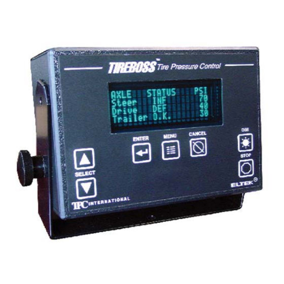
TIREBOSS Tire Pressure Control SYSTEM DESCRIPTION The TIREBOSS Tire Pressure Control system consists of a computerized Operator Control Unit (OCU), mounted in the cab, which monitors system activity and displays clear text messages to the operator of the vehicle. The OCU is linked to a computerized Valve Control Module (VCM) and pneumatic control valves located outside of the cab. -
Page 4: Safety Features
This feature limits the selections to the driver and ensures only the appropriate tire pressures are being used for current vehicle load. In addition to the system safety features outlined above, it should be noted that the TIREBOSS systems use only quality components, such as DOT approved drive axle air hosing. -
Page 5: System Schematics And Diagrams
TIREBOSS Tire Pressure Control SERVICE MANUAL SECTION 1 SYSTEM SCHEMATICS AND DIAGRAMS... -
Page 6: System Overview
TIREBOSS Tire Pressure Control SERVICE MANUAL SYSTEM OVERVIEW Steer Shut-off Valves (located on frame) Speed/Ignition Operator Cable Control Unit Operator Control Cable Steer Axle Main Line TRUCK (optional) TPCS Air Supply Line Valve Box Truck Wet Tank Pressure Protection Valve... -
Page 7: Air And Electrical Schematic
TIREBOSS Tire Pressure Control SERVICE MANUAL OPERATOR TIREBOSS CONTROL UNIT AIR and ELECTRICAL SCHEMATIC Truck Battery The ‘switching out’ of OCUs between (12 V / 24 V) trucks is not recommended as settings and speed functions have to be adjusted per truck specifi... -
Page 8: Truck With Receiver Tank
TIREBOSS Tire Pressure Control SERVICE MANUAL Install Temporary Gauge Here to set Dryer Governor Pressure Protection Valve to 125psi (Internal Relief Valve) One Way Adjusted to 100 psi Internal Standpipe Check Valve TIREBOSS - mounted inside wet tank VALVE BOX... -
Page 9: Air And Electrical Schematic (With Ad-Is Dryer)
Tank AD-IS Factory Pressure Air Drying Relief Valve NOTE: Pressure Protection Valve System can be mounted at optional wet tank or at TIREBOSS Valve Box Air Governor Truck Compressor Brake Pressure Protection pneumatic control lines Switch Air main air supply lines... -
Page 10: Wiring Diagram
Black & Green wires are not not recommended as (From Data Link, Impulse connected on GPS equipped settings and speed Sender, Frequency Gen- functions have to be TIREBOSS systems. adjusted per truck erator or OPERATOR Marked G on rear panel specifi cations. Frequency Convertor) - Page 11 TIREBOSS Tire Pressure Control SERVICE MANUAL OPERATOR CONTROL CIRCUIT BOARD ELTEK 1483-00 Speed Board Mount Datalogger Stand Off Posts Header Programming Speed Board Header Header 6 5 4 3 2 1 Sonalert Header Power ON/ OFF Header Speed/Ignition Power/Data Header...
- Page 12 TIREBOSS Tire Pressure Control SERVICE MANUAL VALVE CIRCUIT BOARD #1393-01 VALVE BODY HEATER FUSE CONTROL RELAY BRAKE PRESSURE PROTECTION SWITCH V6-0615 f:tec\manuals\Service\SERVICEv5.indd -...
- Page 13 TIREBOSS Tire Pressure Control SERVICE MANUAL VALVE CIRCUIT BOARD #1393-02 White Wire (Positive) Black Wire (Ground) 12/24v NOTE - Black Wire to neg. battery post Jumper -VBAT +VBAT Steer unless truck has a (blue) Power Disconnect Switch. Then Black Wire must be con- nected to truck frame.
-
Page 14: Valve Circuit Board Indicator Light Descriptions
The LED indicator lights on the valve circuit board may assist in trouble shooting and/or diagnosing of the electronic circuits. When the TIREBOSS system is operating and communicating correctly, the LED indicator lights will illuminate as follows... *Key OFF - LED L2 and LED L4 illuminated solid green (with main power available at +V Bat) *Key ON - All LED’s illuminated solid green and LED L3 fl... -
Page 15: Data Logger Connections
PIN 9 (no connect) Pin 9 (no connect) PIN 8 RTS (not used)(white) PIN 7 CTS (not used)(grey) PIN 6 DSR (not used)(purple) The internal TIREBOSS OCU connections are as follows: Internal J5 header TIREBOSS DB9 SUB D Pin 1 (TX) (White/Red wire) -
Page 16: Valve Box Diagram
SERVICE MANUAL TIREBOSS Tire Pressure Control VALVE BOX System DIAGRAM Serial Steer Axle Static Tank (if equipped) Number Drive Axle Static Tank Trailer Axle Static Tank (if equipped) Orifi ce Fitting Orifi ce Fitting Orifi ce Fitting Vent Power/Communication Elec-... -
Page 17: Operator Control Unit Button And Screen Descriptions
TRAILER CIRCUIT OVERRIDE FUNCTION This function is used only when pulling a trailer that is not equipped with TIREBOSS Tire Pressure Control or when not pulling a trailer. Non-equipped or non-connected trailers will cause the TRAILER “AIR FLOW RESTRICTION” alert to activate. -
Page 18: Operator Control Unit Selection Sequences
(ie. ValV202) ENTER MENU DOWN TPC SYSTEM ...screen will return to normal view ...will display TPC Serial Number of SERIAL NUM- after 30 seconds Valve Box (ie. MigBCA00J0000) fi ve times ...this number MUST match the serial number inside the valve box on VCM bracket. -
Page 19: Operator Guide And Pressure Setting Cab Cards
SERVICE MANUAL TIREBOSS Tire Pressure Control OPERATOR GUIDE AND PRESSURE SETTING CAB CARDS Supplied with each system at time of install is an Operator Guide and a set of Pressure Setting Cab cards. Pressure Setting Cab Cards are specifi c to each truck and application. -
Page 20: Adjustments And Settings
TIREBOSS Tire Pressure Control SERVICE MANUAL SECTION 2 ADJUSTMENTS AND SETTINGS... -
Page 21: Truck Air Compressor Governor Adjustment
Valve opposite of the electric pressure switch. (Refer to Pressure Protection Valve Adjustment section in this guide). -with the TIREBOSS Operator Control Unit turned off, ensure truck air compressor is set to a min. 115psi cut-in pressure to a maximum 132-135 psi cut-out pressure (the pressure at which the dryer unloads). - Page 22 Valve opposite of the electric pressure switch. (Refer to Pressure Protection Valve Adjustment sec- tion in this manual). -with the TIREBOSS Operator Control Unit turned off, fi rst ensure truck air compressor is set to 135psi, (the pressure that is maintained after the dryer has unloaded and pressure has stabilized).
-
Page 23: Pressure Protection Valve Adjustment
Close wheel end valves. Remove one end of an drive hose at hanger fi tting. With the truck wet tank at zero pressure, start truck, turn TIREBOSS control “ON” and leave engine idling. Air will begin fl owing through pressure protection valve and out of hanger at open fi tting. -
Page 24: Viewer Program Installation
Control Files folder as follows: When a new fi le is sent (by e-mail) to load into the controller, right click on the attachment & select “Save As” to save the fi le to the directory C:\Program Files\TireBoss Viewer\ Control Files. If it is replacing an existing fi le, click “Yes” when the screen is displayed asking if you want to replace the fi... -
Page 25: Trouble Shooting
TIREBOSS Tire Pressure Control SERVICE MANUAL SECTION 3 TROUBLE SHOOTING... -
Page 26: Warnings
WARNINGS The system has seven ‘warning conditions’. The following chart indicates the cause of the warnings and some possible solutions. If the problem persists, contact TPC International or one of their authorized installers, and speak to a service technician. WARNING... -
Page 27: Alerts
ALERTS The system has ten ‘alert conditions’. The following chart indicates the cause of the alerts and some possible solutions. If the problem persists, contact TPC International or one of their authorized installers, and speak to a service technician ALERT... -
Page 28: Heater Current Error
-test ohms resistance at heaters to determine if (see page 3-4 faulty heater or page 3-6) -check VB program (TPC only) TEMP SENSOR ..the thermistor (valve block tem- - check thermistor wires at valve board perature sensor) has malfunctioned... - Page 29 SERVICE MANUAL TIREBOSS Tire Pressure Control “HEATER CURRENT ERROR” ALERT Valve Circuit Board 1393-01 (Note: Valve board 1393-01 only uses 12V - 30 watt heaters) This alert appears on the cab controller display to indicate a problem related to the system valve heater circuit operation.
- Page 30 This can only be checked by TPC or their certifi ed installers. Check the VB program in the operator controller to ensure the correct heater wattage is indicated in the protected parameters.
- Page 31 SERVICE MANUAL TIREBOSS Tire Pressure Control “HEATER CURRENT ERROR” ALERT Valve Circuit Board 1393-02 (Note: Valve board 1393-02 accommodates both 12V and 24V systems) This alert appears on the cab controller display to indicate a problem related to the system valve heater circuit operation.
- Page 32 This can only be checked by TPC or their certifi ed installers. Check the VB program in the operator controller to ensure the correct heater wattage is indicated in the protected parameters.
-
Page 33: Ocu "Heater Info" Screen
SERVICE MANUAL TIREBOSS Tire Pressure Control OCU “HEATER INFO” SCREEN Note: All Operator Control Units manufactured after the Spring 2005 have a heater information screen available. (Factory heater settings must be activated for this function to operate.) To access this information/ test screen, use the following procedures.. -
Page 34: "Valve No Power" Alert
SERVICE MANUAL TIREBOSS Tire Pressure Control “VALVE NO POWER” ALERT Valve Circuit Board 1393-01 This alert appears on the Cab Controller display to indicate an existing problem related to the system Valve Controller circuit board power. Notes: In the following descriptions, “RLY” is Relay and “VPS” is Valve Power Supply. - Page 35 SERVICE MANUAL TIREBOSS Tire Pressure Control On the Valve Controller board, check if LED light (L1) is On or Off. Using a multi-meter, set to DC volts, connect the negative lead at the –VBAT terminal. - If L1 is On, determine if voltage is present at terminal VPS.
- Page 36 SERVICE MANUAL TIREBOSS Tire Pressure Control “VALVE NO POWER ALERT” Valve Circuit Board 1393-02 This alert appears on the Cab Controller display to indicate an existing problem related to the system Valve Controller circuit board power. Notes: In the following descriptions, “RLY” is Relay and “VPS” is Valve Power Supply.
- Page 37 SERVICE MANUAL TIREBOSS Tire Pressure Control On the Valve Controller board, check if LED light (L2) is On or Off. Using a multi-meter, set to DC volts, connect the negative lead at the –VBAT terminal. - If L2 is On, determine if voltage is present at terminal VPS.
-
Page 38: Slight Air Leak Through Exhaust Port
SERVICE MANUAL TIREBOSS Tire Pressure Control SLIGHT AIR LEAK THROUGH EXHAUST PORT Note: A slight air leak, as referenced here, can be identifi ed by holding your hand over the exhaust port (bottom of the valve box assembly) and detecting a slow build up of pressure A slight leak through the exhaust port can come from one of two places. - Page 39 TIREBOSS SYSTEM “SHUT OFF” at the controller. You are checking the supply side of the circuit and the TIREBOSS system should be off for this portion of the test. Once again this will not allow a tire pressure drop as it is independent of the tire supply circuit.
-
Page 40: Trans Range Error" Alert
Turn all wheel valves off to isolate tires. Inside the TIREBOSS Valve Box, remove cover of Valve Control Module by removing the eight screws. Remove the airline to the transducer at push-to-lock fi tting on side of Valve Control Module. - Page 41 SERVICE MANUAL TIREBOSS Tire Pressure Control “TRANS RANGE ERROR” ALERT ... con’t Transducer Adjusting Screw Transducer Transducer Wires (Red Green and Black) Transducer Manifold *SIDE VIEW Ground Terminal Positive Terminal (-VBAT) (+VBAT) Air line to Transducer Attach Red probe here...
- Page 42 SERVICE MANUAL TIREBOSS Tire Pressure Control TRANSDUCER INPUT/OUTPUT VOLTAGE CHART INPUT OUTPUT INPUT OUTPUT INPUT OUTPUT VOLTAGE VOLTAGE VOLTAGE VOLTAGE VOLTAGE VOLTAGE 3-17 V6-0615 f:tec\manuals\Service\SERVICEv5.indd -...
-
Page 43: Maintenance Procedures
TIREBOSS Tire Pressure Control SERVICE MANUAL SECTION 4 MAINTENANCE PROCEDURES... -
Page 44: System Maintenance Overview
SERVICE MANUAL TIREBOSS Tire Pressure Control System Maintenance Overview Attached is the information required to properly maintain your TIREBOSS™ Tire Pressure Control system for optimum performance. DAILY - Drain wet tank - Observe moisture content - Walk around the truck , and visually inspect system and wheel ends WEEKLY - Inspect Rotary Unions. -
Page 45: Rotary Union Maintenance
The grease should be tacky, have excellent water resistance, and have an extremely high dropping point (260o C) A recommended grease available direct from TIREBOSS is “Nemco Red Max EP1.5” FREQUENCY... -
Page 46: Air Flow Check Procedures
Close all wheel end valves at the tires for drives,steers and trailers (if applicable). Bleed air from the main air line at the fi ller port on the side of the TIREBOSS Tire Pressure Control System Valve Box. -
Page 47: Tire Pressure Loss Warning' Check Procedures
Tire Pressure Control ‘Tire Pressure Loss Warning’ Check Procedures In the event of a line breakage or tire failure, the TIREBOSS Tire Pressure Control System will immediately warn the operator with an audible alert and a warning fl ashing on the Operator Control Unit screen. -
Page 48: Static Tank Orifi Ce Testing
SERVICE MANUAL TIREBOSS Tire Pressure Control Static Tank Orifi ce Testing Shut off all wheel valves at the tires Remove air line (indicated as “A”) from fi tting on side of tank (indicated as “Fitting B”) and install a 200 p.s.i. test pressure gauge. Install gauge in line as shown. -
Page 49: Testing Overspeed Function
TIREBOSS Tire Pressure Control Testing Overspeed Function The TIREBOSS system is equipped with an Overspeed function which will automatically increase the selected pressure/speed setting to the next pressure/speed setting in the event of an continuous Overspeed situation. The testing of this function should be done on an annual basis. - Page 50 SERVICE MANUAL TIREBOSS Tire Pressure Control Wheel End Valve Operational Check Wheel End Valves (WEV) Operational Checks and AIR Flow Checks Run truck with all wheel valves open to highest tire pressure setting (i.e. 95 or 100 PSI). Shut down truck and turn on ignition switch so controller is in operational mode.
-
Page 51: Drive Axle Hanger Bracket And Hose Maintenance
SERVICE MANUAL TIREBOSS Tire Pressure Control Drive Axle Hanger Brackets and Hose Maintenance Typical Wheel Hanger Position & Hose Length for units NOT using tire chains. Note position of hanger brackets. Units not using tire chains should have the hanger brackets adjusted to the lowest possible position without going... - Page 52 SERVICE MANUAL TIREBOSS Tire Pressure Control Drive Axle Hanger Brackets and Hose Maintenance Typical Wheel Hanger Position & Hose Length for units NOT using tire chains. Note position of hanger brackets. Units not using tire chains should have the hanger brackets adjusted to the lowest possible position without going below the centre line of Rotary Unions 1.5 ”...
- Page 53 TIREBOSS Tire Pressure Control Tire/Wheel Changing Procedures - Steer Tires WARNING - ALL valve cores MUST be removed for the TIREBOSS system to operate prop- erly. Failure to remove valve cores can cause unsafe or dangerous driving conditions as the TIREBOSS system will be unable to maintain proper tire pressures.
- Page 54 Undo TIREBOSS wheel hoses from the wheel end manifold swivel fi ttings Undo wheel nuts and remove outer wheel. (In most cases the rim will fi t over the TIREBOSS wheel end manifold) Before removing the inner wheel, ‘MARK’...
- Page 55 Operator Control Unit (switch on back left side) Relieve air pressure from the TIREBOSS tire mainline by the Schrader valve (2nd from bottom Schrader marked with a ‘T’) located on the right side of the TIREBOSS valve box. (usually located on the truck frame) ‘MARK’...
- Page 56 SERVICE MANUAL TIREBOSS Tire Pressure Control Tire/Wheel Changing Procedures - Diagrams Rotary Union Compres- To Valve Stem sion Fitting Manifold Swivel Fitting Wheel Hose Swivel Fitting Hose Adaptor Fitting Manifold Assembly Hub Cap Fitting Inner (Caution... always hold this fi tting...
- Page 57 SERVICE MANUAL TIREBOSS Tire Pressure Control Tire Pressure Control Systems – Service Inspection – MONTHLY Date: ______________________________Work Order #: _________________________________ Customer Name __________________________________________________________________ Unit #: _____________________________Mileage: ______________________________________ Vehicle Make: _______________________Inspected By: __________________________________ = Repairs Completed Inspection Codes = Pass...
- Page 58 Soap/water spray test all hoses, hardware and pneumatic connections with system at higher pressure (i.e. 100 psi) (7 bar) AIR SUPPLY SYSTEM Check dryers unloading OK (check with TIREBOSS system off) Refer to Dryer Service Manual Check wet tank drain operation...
- Page 59 SERVICE MANUAL TIREBOSS Tire Pressure Control Tire Pressure Control Systems – Service Inspection – A – Each Six Months Date: ______________________________ Work Order #: ____________________________ Inspection: A Service B Service Unit #: __________________________________ Customer Name: _____________________ Mileage: ________________________________ Vehicle Make: _______________________...
- Page 60 SERVICE MANUAL TIREBOSS Tire Pressure Control Service Inspection Explanations – SIX MONTH OPERATION OF SYSTEM Ensure all manual valves are open for this test Check operation of Operator Control Unit... Check that dimming function is operational (Screen should dim and white lettering should glow).
- Page 61 SERVICE MANUAL TIREBOSS Tire Pressure Control Tire pressure Control Systems – Service Inspection – B – Annual Complete this inspection in addition to the “A” (six month) inspection Inspection Codes = Pass = Failed = Repairs Completed *See next page for inspection explanations...
- Page 62 SERVICE MANUAL TIREBOSS Tire Pressure Control Service Inspection Explanations – ANNUAL AIR SUPPLY SYSTEM Visual check of compressor discharge line/fi ttings... Soap/water spray test all hoses and fi ttings for leaks. Check for rub-through. Ensure line is securely fas- tened and protected.
-
Page 63: Valve Rebuild Procedures
TIREBOSS Tire Pressure Control SERVICE MANUAL SECTION 5 VALVE REBUILD PROCEDURES... - Page 64 Repeat the process for each valve body if required. When working with more than one valve body ensure all cable harness’s and air lines are returned to the original position when reassembling the valve bodies. NOTE - One VALVE PACK MAINTENANCE KIT is required for each valve in the TIREBOSS system. Valve Removal ...
- Page 65 VALVE REBUILD PROCEDURE con’t Disconnection inside box Remove 1/4” plastic airline from valve NOTE - It may be necessary to remove line from static tank fi rst to allow enough movement to disconnect from valve -Systems with valve heaters only- Cut tie strap from wire bundle and un-plug heater harness ...
- Page 66 VALVE REBUILD PROCEDURE con’t Disassembly and Replacement of Orifi ce Filters Filters Using two wrenches, remove Static Tank Orifi ce located on top of static tank Remove and replace 2 snap rings and fi lters supplied in valve pack maintenance kit. CAUTION - When re-installing, do not over tighten, as brass fi...
- Page 67 VALVE REBUILD PROCEDURE con’t VALVE BODY Y-FILTER - Clean metal screen inside Y-fi lter and replace seal washer BREAKDOWN DRAWING #1 *included in Valve Pack Maintenance Kit BRASS PLUG AIR SUPPLY (only on SIDE some MANIFOLD valves) O-RING* (Do not remove) INLET CHECK VALVE*...
- Page 68 *between valve body and solenoid VALVE PACK NOTE - One VALVE PACK MAINTENANCE MAINTENANCE KIT KIT is required for each valve in the TIREBOSS system. (Eg. Systems controlling drives and trailers will Part #CT-VPO-TB require two VALVE PACK MAINTENANCE KITS.)
- Page 69 VALVE REBUILD PROCEDURE con’t Allen Screw Rubber O-ring 16000-116 Valve Seat Poppet Spring Rubber O-ring Cartridge Body Rubber O-ring VALVE CARTRIDGE Rubber O-ring 16000-026 Part #16750 BREAKDOWN DRAWING #3 (Exploded view for reference only, parts not sold separately) Aluminium Piston Shaft Y-FILTER Part #59-003-01 BREAKDOWN DRAWING #4...
- Page 70 VALVE REBUILD PROCEDURE con’t Rubber O-ring 16000-116 Spring Spring Washer Rubber O-ring VALVE Cartridge Body CARTRIDGE Rubber O-ring Part #16750 New Style Rubber O-ring BREAKDOWN DRAWING #3 16000-026 (Exploded view for reference only, parts not sold separately) Valve Seat Poppet Brass End Cap Lock Washer Allen Screw...
Need help?
Do you have a question about the TIREBOSS and is the answer not in the manual?
Questions and answers