Chapters
Table of Contents

Related Manuals for Apec Water Ultimate RO


Summary of Contents for Apec Water Ultimate RO
- Page 1 ULTIMATE REVERSE OSMOSIS SYSTEM INSTALLATION INSTRUCTION & OWNER’S MANUAL Ver 1.0-H Ver 1.0-H www.FreeDrinkingWater.com www.FreeDrinkingWater.com All Rights Reserved © APEC Water Systems All Rights Reserved © APEC Water Systems...
-
Page 3: Table Of Contents
Please keep this Owner’s Manual for future reference. Please keep this Owner’s Manual for future reference. It contains useful information on how to maintain and care for your It contains useful information on how to maintain and care for your APEC Reverse Osmosis water filter system. -
Page 4: Installation
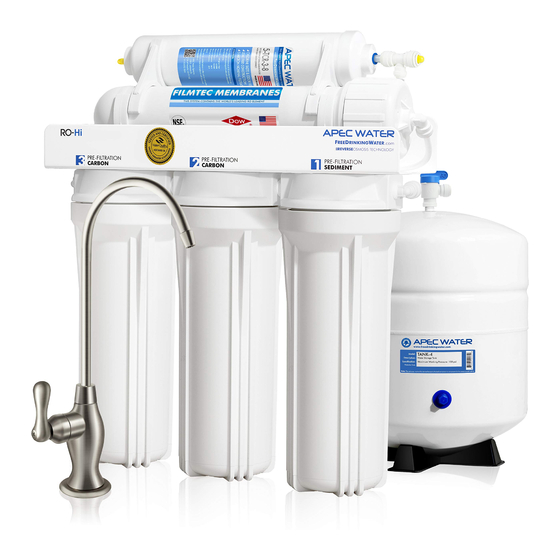
Thank you for choosing APEC reverse osmosis systems. Thank you for choosing APEC reverse osmosis systems. You now own the finest water filter in America. You now own the finest water filter in America. Please read and become familiar with instructions and parts needed before proceeding with the Please read and become familiar with... - Page 5 Components included with the RO system: Components included with the RO system: Make sure you have all these parts before starting installation. Make sure you have all these parts before starting installation. 1 RO system head 1 RO system head 3 Pre-filters in 3 Housings 3 Pre-filters in 3 Housings 1 Storage tank...
- Page 6 Component Itemization: Component Itemization: Sediment pre-filter and housing (1 Sediment pre-filter and housing (1 -stage filter) -stage filter) Carbon block pre-filter and housing ( 2 Carbon block pre-filter and housing ( -stage filter) -stage filter) Carbon block pre-filter and housing ( 3 Carbon block pre-filter and housing ( 3 -stage filter) -stage filter)
- Page 7 There are 2 types of fittings provided for connecting the system There are 2 types of fittings provided for connecting the system Fitting Types: Fitting Types: 1. Quick-Connect (QC) fitting: 1. Quick-Connect (QC) fitting: (no insert, sleeve, or nut insert, sleeve, or nut Most of the fittings on the RO unit are this Most of the fittings on the RO unit are this type.
- Page 8 THERE ARE TWO PARTS TO INSTALLING THE RO SYSTEM: THERE ARE TWO PARTS TO INSTALLING THE RO SYSTEM: Part I. Part I. Assemble the filters and housings onto the main system Assemble the filters housings onto the main system Part II. Part II.
- Page 9 PART II. INSTALLING THE SYSTEM PART II. INSTALLING THE SYSTEM Space: Make sure there is sufficient space under the counter for installation (an area of about Space: Make sure there is sufficient space under the counter for installation (an area of about 17”L x 6”W x 18”H for the system, 11”D x 18”H for tank).
- Page 10 Fig. 5A - Needle Valve Installation. Fig. 5A - Needle Valve Installation. Attach the needle valve (C) to water supply adapter (A). Please apply 5-6 wraps of Attach the needle valve (C) to water supply adapter (A). Please apply 5-6 wraps of teflon tape to needle valve prior to connecting it to the water supply adapter (A).
- Page 11 3. Recommend Connection For Flex Line Riser: See Fig.6A. & Fig. 6D. Loosen nut and 3. Recommend Connection For Flex Line Riser: See Fig.6A. & Fig. 6D. Loosen nut and separate cold water riser tube from faucet shank. Gently bend riser tube so that the Feed separate cold water riser tube from faucet shank.
- Page 12 Fig. 6C Fig. Fig. 6D Fig. 6D Fig. 6E Fig. 4. Needle Valve: See Fig. 6C. Screw the Needle Valve onto the Adaptor tightly. Apply 6-8 rounds 4. Needle Valve: See Fig. 6C. Screw the Needle Valve onto the Adaptor tightly. Apply 6-8 rounds of Teflon tape onto Needle Valve before attaching it to the Adaptor.
- Page 13 Step 2: Drain Saddle Installation Step 2: Drain Saddle Installation Note: Note: To avoid annoying drainage noise, mount drain line as low as possible To avoid annoying drainage noise, mount drain line possible on the vertical tailpiece, or on horizontal tailpiece. on the vertical tailpiece, or on horizontal tailpiece.
- Page 14 3. See Fig.9, 9A. Make sure to align the drain saddle hole to the drilled hole perfectly. 3. See Fig.9, 9A. Make sure to align the drain saddle hole to the drilled hole perfectly y. y y Mis-aligning these two holes will block the drain water and cause membrane damage. Attach the Mis-aligning these two holes will block the drain water and cause membrane damage.
- Page 15 3. For Porcelain Sink: Porcelain enameled sinks can readily be chipped if care is not exercised Porcelain Sink: Porcelain enameled sinks can readily be chipped if care is not exercised when drilling the hole. Before starting the drill motor, apply firm downward pressure on the bit when drilling the hole.
- Page 16 Step 6: Connecting The System Step 6: Connecting The System Summary of Tubing Connections: Summary of Tubing Connections: There are 4 connections: There are 4 connections: See Fig. 11 and 11A See Fig. 11 and 11A Point A to X: Point A to Connect RO to COLD water supply —...
-
Page 17: Feed Water Connection
Fig. 11A Fig. 11A Details on Tubing Connections: Details on Tubing Connections: To ensure a smooth and correct installation, please connect the water lines following the se- To ensure a smooth and correct installation, please connect the water lines following the se- quence and order outlined below. - Page 18 3. Point W Waste water connection: Point W Waste water connection: Tubing color: Tubing color: Black tubing. Connect the BLACK tubing from the RO to the Drain Saddle. Black tubing. Connect BLACK tubing from the RO to the Drain Saddle. Fitting type: Fitting type: Quick-Connect fitting on drain saddle.
- Page 19 7. Point Y 7. Point Y Tank’s input & output connection: Tank’s input & output connection: Prepare tank: See Fig.12. Apply 6-8 wraps of Teflon tape to tank’s threaded Output stem on top of Prepare tank: See Fig.12. Apply wraps Teflon tape to tank’s threaded Output stem...
- Page 20 Using RO for Ice-maker only: Using RO for Ice-maker only: If you want the RO to feed your ice-maker (fridge) only, you should still connect the RO faucet you want the RO to feed your ice-maker (fridge) only, you should still connect the RO faucet as a 2nd outlet.
-
Page 21: Maintenance
(i.e. allow the system to rest at least a few hours a day). To properly maintain your APEC drinking water system, To properly maintain your APEC drinking water system, please use only genuine APEC Water replacement filters at please use only genuine APEC Water replacement filters at www.freedrinkingwater.com/filters www.freedrinkingwater.com/filters... - Page 22 2) Open housing: Have the RO standing upright. Slip the plastic wrench onto the #1 housing. 2) Open housing: Have the RO standing upright. Slip the plastic wrench onto the #1 housing. Looking down from a top view, you should open the housing turning clockwise. If necessary, lay Looking down from a top view, you should open the housing turning clockwise.
- Page 23 5) Check for leaks! 5) Check for leaks! 6) Drain the first tank of water (through faucet) to flush out the new membrane! The 2 Drain the first tank of water (through faucet) to flush out the new membrane! The 2 tank tank of water is ready for use.
-
Page 25: System Flow Diagram
OWNER’S MANUAL Please read this section for useful RO system and Please read this section for useful RO system and maintenance information. maintenance information. TABLE OF CONTENT TABLE OF CONTENT Part I: Part RO Basics RO Basics Basic terms ................. Basic terms ................. -
Page 26: Part I: Part I: Ro Basics
Part I: RO BASICS Part I: RO BASICS This section provides basic concepts on how an RO system works, how it performs in relation to your This section provides basic concepts how an RO system works, how it performs relation to your house’s water condition. -
Page 27: Water Pressure -- The Most Important Factor Water Pressure -- The Most Important Factor
3) Water Pressure – The Most Important Factor! 3) Water Pressure – The Most Important Factor! RO systems run on water pressure. Therefore your water pressure has the most direct effect on how systems run on water pressure. Therefore your water pressure has the most direct effect on how well your RO will perform. - Page 28 6) How Full Can My Tank Fill Up? 6) How Full Can My Tank Fill Up? Your incoming water pressure determine how full and how fast the storage tank will be filled up. Your incoming water pressure determine how full and how fast the storage tank will be filled up.
-
Page 29: Icemaker And Multiple Output Points
delivery pressure: delivery pressure: 14-gallon tank’s 14-gallon tank’s 10 gallons —> 50 psi output pressure ( pressure inside tank ) gallons —> 50 psi output pressure pressure inside tank ) 9.0 gallon —> 40 psi 9.0 gallon —> 40 psi 7.8 gallon —>... -
Page 30: How To Test Your Water Pressure
11) How to Test Your Water Pressure: 11) How to Test Your Water Pressure: Get a water pressure gauge that adapts onto your sink or garden faucet (from hardware store), Get a water pressure gauge that adapts onto your sink or garden faucet (from hardware store), attach gauge onto faucet, turn water on to FULL, then take a reading. -
Page 31: Ro Head Diagram
Part II: Trouble-Shoot Guide Part II: Trouble-Shoot Guide For Newly Installed RO System For Newly Installed RO System After installation, if you encounter any of the problems described below, please follow this guide to After installation, if you encounter the problems described below, please follow this guide to troubleshoot. -
Page 32: Humming Noise
1) RO Makes Humming Noise Makes Humming Noise When RO makes a humming noise, most likely it’s caused by air bubbles being trapped in the When RO makes a humming noise, most likely it’s caused by air bubbles being trapped in the “Check Valve”... - Page 33 Output line is crimped —> Remove crimp Output line is crimped —> Remove crimp Incorrect installation —> See Fig.11 & 11A. Verify all line connections. Incorrect installation —> See Fig.11 & 11A. Verify all line connections. Tank defective, no pre-charge pressure —> Set tank pre-charge to 5-7 psi. Tank defective, no pre-charge pressure —>...
-
Page 34: Slow Slow Output
3) Sluggish Flow At Dispensing Faucet 3) Sluggish Flow At Dispensing Faucet Insufficient water pressure (see “ Insufficient water pressure (see “ ” for explanation) —> Check water pressure. If too ” for explanation) —> Check water pressure. If too RO Basics Basics low for this chosen RO model, either increase your water pressure or add pump to RO system. - Page 35 6) System Does Not Shut-Off: Waste water runs all day - and Never Stops 6) System Does Not Shut-Off: Waste water runs all day - and Never Stops Input pressure way too low (below 30psi). Not enough pressure to shut off the RO at all —> Input pressure way too low (below 30psi).
-
Page 36: Tds Level Higher Than Normal
Test#2: Test Check Valve and ASO valve: Test#2: Test Check Valve and ASO valve: Make sure there is some water in the tank (tank not empty). Make sure there is some water in the tank (tank not empty). Remove the Black drain line from the drain saddle (so you can check waste flow drainage). Remove the Black drain line from the drain saddle (so you can check waste flow drainage). -
Page 37: Filter Housing Is Leaking
Dispense some water from the RO faucet, this water comes directly from Dispense some water from the RO faucet, this water comes directly from Test #1 TDS from tank: Test #1 TDS from tank: the tank. Test TDS, record the reading, then Do Test #2. the tank. -
Page 38: Tank Ball Valve Is Leaking
10) There is a leak at the Tank ball valve connection 10) There is a leak at the Tank ball valve connection If you are experiencing a leak from where the tank ball valve attaches to the tank stem, you may If you are experiencing a leak from where the tank ball valve attaches to... -
Page 39: Other Information
OTHER INFORMATION OTHER INFORMATION AirGap Faucet Installation AirGap Faucet Installation There are 3 colored tubings on your Air-Gap faucet. At the end of each 1/4” tubing there is a There are 3 colored tubings on your Air-Gap faucet. At the end of each 1/4” tubing there is a “Quick Connect”... - Page 40 How wastewater is disposed via Air-Gap faucet: How wastewater is disposed via Air-Gap faucet: Waste water is routed through the Air-Gap faucet prior to being drained off into the standard drain- Waste water is routed through the Air-Gap faucet prior to being drained off into standard drain- pipe outlet.
-
Page 41: W W
LIMITED PRODUCT WARRANTY LIMITED PRODUCT WARRANTY Scope Scope APEC takes pride in selling a superb line of products, including this reverse osmosis system (“Product”). As such, APEC expressly APEC takes pride in selling a superb line of products, including this reverse osmosis system (“Product”). As such, APEC expressly warrants to the original purchaser that, for a period of one (1) year from the date of purchase, the Product will be reasonably free of warrants to the original purchaser that, for a period of one (1) year from the date of purchase, the Product will be reasonably free of defects in materials and workmanship. - Page 42 CONDITIONS THAT RENDER THIS LIMITED PRODUCT WARRANTY VOID CONDITIONS THAT RENDER THIS LIMITED PRODUCT WARRANTY VOID THIS LIMITED PRODUCT WARRANTY SHALL BE VOID IF: THIS LIMITED PRODUCT WARRANTY SHALL BE VOID 1. The Product is not operated in compliance with normal municipal water conditions for which the particular model of this Product 1.
- Page 44 Advanced Purification Engineering Corp. Advanced Purification Engineering Corp. 1320 S Johnson Drive 1320 S Johnson Drive City of Industry, CA 91745 City of Industry, CA 91745 For questions or comments please visit our website at: For questions or comments please visit our website www.FreeDrinkingWater.com www.FreeDrinkingWater.com...
Need help?
Do you have a question about the Ultimate RO and is the answer not in the manual?
Questions and answers