Megger SVERKER 900 User Manual
Relay and substation test system
Hide thumbs
Also See for SVERKER 900:
- Application note (12 pages) ,
- Technical manual (33 pages) ,
- Quick manual (4 pages)

Related Manuals for Megger SVERKER 900


Summary of Contents for Megger SVERKER 900
- Page 1 SVERKER 900 Relay and Substation Test System User’s Manual Art No. ZP-CR02E Doc. CR0333LE V12a 2016...
- Page 3 © 2013-2016, Megger Sweden AB. All rights reserved. The contents of this manual are the property of Megger Sweden AB. No part of this work may be reproduced or transmitted in any form or by any means, except as permitted in written license agreement with Megger Sweden AB. Megger Sweden AB has made every reasonable attempt to ensure the completeness and accuracy of this document.
-
Page 4: Table Of Contents
Contents 1 Safety Switch buttons ..........18 ............. 6 Start SVERKER 900 ........... 18 1.1 General ............... 6 4.2 Home menu ............19 Symbols on the instrument ......... 6 Home menu buttons ........19 System configuration ........19 1.2 Safety instructions ..........6 Generator configuration ........ - Page 5 View and reuse test files ........41 Storage file ............. 41 Reference file ..........41 Transfer files to PC ..........41 Copy test files from USB stick to SVERKER 900.. 42 4.10 Calibration ............42 Calibration procedure ........42 Automatic calibration ........42 Manual calibration ..........
-
Page 6: Safety
1 SAFETY 1 Safety 1.1 General 1.2 Safety instructions Warning Important Read and comply with the following in- structions. High voltage/current on output terminals. Always comply with local safety regula- The instrument is equipped with a power tions. cord with integral safety ground pin. The equipment must be connected to a grounded mains outlet. - Page 7 Do not expose the instrument to rain or moisture. Refer all servicing to Megger authorized personnel. If you need to return the instrument, please use either the original crate or one of equiv-...
-
Page 8: Introduction
Impedance instrument The rugged hardware design is built for field use over a wide temperature range. SVERKER 900 is a three-phase test equipment. It can generate voltage and current from its four voltage generators and three current generators respectively, receive binary inputs and a binary output that is a make/brake contact. -
Page 9: Unpack System
Unpack the unit and check for evidence of any ship- For technical assistance please contact your local ping damage. If there is any visual damage, imme- representative or direct your request to Megger in diately notify the freight carrier to make a damage Sweden. -
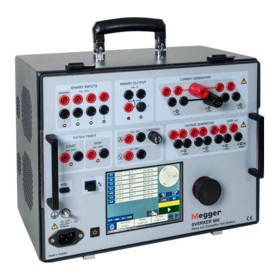
Page 10: Instrument Description
3 INSTRUMENT DESCRIPTION 3 Instrument description 3.1 Panel 3.2 The lid Inside the lid are: 1. Binary inputs 2. Binary output ▪ Jumpers 3. F2 fuse ▪ 4. Current generators I1, I2, I3 CTM-box for use with the CT magnetization instrument 5. -
Page 11: Binary Inputs
The SVERKER 900 have 4 binary inputs, independ- The binary output is a make/break contact that is ent programmable gate circuits that permit simple actuated when the SVERKER 900 is set to ON-gener- selection of the desired mode for voltage or contact ating or OFF-generating mode. -
Page 12: Current Generators: I1, I2, I3
3 INSTRUMENT DESCRIPTION 3.5 Current generators: I1, Current generators in series: I1 – I2 – I3 I2, I3 The current generators can be used separately, in par- allel or in series. Constant power output in many cases eliminates the need to connect the current channels in parallel or series to test high burden relays. -
Page 13: Voltage Generators: U1, U2, U3 And U4
3 INSTRUMENT DESCRIPTION 3.6 Voltage generators: U1, Voltage generators in parallel: U1 // U2 // U3 // U4 U2, U3 and U4 The voltage generators can be used separately, in parallel or in series. ▪ All outputs are independent from sudden changes in mains voltage and frequency, and are regulated so Voltage range Power (max) -
Page 14: Extra Timer
3 INSTRUMENT DESCRIPTION 3.7 Extra timer At the opening or closing of contacts. The SVERKER 900 has two independent gate inputs that permit simple selection of the desired mode for When a generator is turned on or off, timing operation. or that a trip signal stops the generat- To monitor operation of the contacts in the device ing or that an open current circuit is under test, a light is provided for each gate. -
Page 15: A-Meter / V-Meter
3 INSTRUMENT DESCRIPTION 3.8 A-meter / V-meter Ammeter and Voltmeter windows Type U (V) Select AC or DC SVERKER is equipped with an ammeter and voltmeter. Range Auto, 0-9 V, 9-90 V, 90-900 V These instruments can also be used to display resist- Type I (A) Select AC or DC ance, frequency, impedance, phase angle, power and... -
Page 16: Other Entities
The volt and current values can be transfer data, e.g. to a PC for storage or printing. stored to a test file. ▪ Copy test files from USB to SVERKER 900 In the Main menu, the volt- Firmware upgrade via age and current values for pick-up or drop-off, can also SVERKER 900 USB port... -
Page 17: Ethernet Port
0 – 50 mA. The built in ammeter, in SVERKER 900, is connected to measure the current injected into the test object. The ratio between the input and output currents is somewhat depending on the load, e.g. -
Page 18: Operating Sverker 900
4 OPERATING SVERKER 900 4 Operating SVERKER 900 4.1 Local interface Start SVERKER 900 Plug the unit line cord into an appropriate The SVERKER 900 local interface is the manual control power source and press the button and user interface for the unit. All manual entries will be made through the SVERKER 900 local interface. -
Page 19: Home Menu
Main instrument The Main instrument screen is the default screen frequency is changed between the different states. for SVERKER 900, and is presented when started. When “Change State On 0-crossing” is ON it means that the state is not finished until the curve form of Prefault ->... -
Page 20: Generator Configuration
▪ Voltage generator in individual connection 3 AC + AUX AC License file To add additional instruments to the SVERKER 900, press the “License file” button. Insert the USB stick with the license file and follow instructions on the display. -
Page 21: Main Instrument
Balances the phase angle values The Main instrument screen is the default screen for SVERKER 900, and is presented when started. SVERKER 900 will be opened with the settings from Stop last time it was run. Returns to Home menu Non-generating mode This is the default state for the Main instrument. -
Page 22: Numerical Keypad
4 OPERATING SVERKER 900 Press When a trip has been identified on any of the binary inputs the sequence is ended, clock stops and result is displayed. Note The configured off delay time period is to be added before turning off generation. -
Page 23: Finding The Pick-Up And Drop-Off Value Using The Hold Function
4 OPERATING SVERKER 900 Example: You configure the UL2 angle to 240 degrees and press the BALANCE button. UL1 = 0 deg (= 240 + 120) UL2 = 240 deg UL3 = 120 deg (= 240 - 120) When the “condensed” view is selected, only the generators used are shown. -
Page 24: Make Bi Settings
Confirm. Settings are confirmed and window "OR" logic but you can set two or more of the binary closes inputs to a logic “AND” when SVERKER 900 is set to Make BI settings ”Advanced mode” (see "System configuration" on page 19). -
Page 25: Debounce Filter
Press the "10" buttons (see picture above) to set the hysteresis voltage. Set pickup Harmonics and hysteresis voltage level To use the harmonics function SVERKER 900 has to be set to ”Advanced mode” Press for the Home menu. Set debounce time... -
Page 26: Prefault->Fault Instrument
Prefault and Fault. You can configure and activate both stages individu- ally and make SVERKER 900 execute the test and automatically change from Prefault to Fault state. The Prefault state configuration is a valid condition for the test object, meaning it does not trigger during operation. -
Page 27: Prefault View
Set the time duration for how long to gener- Press the graph to make it full screen. ate the Prefault state before SVERKER 900 is Tap on full screen to minimize. automatically entering Fault state. Press the button if you want to acti- vate the selected generators. -
Page 28: Ramping Instrument
4 OPERATING SVERKER 900 4.5 Ramping instrument Press to set ramp speed. Note For the phase angle, the direction is indicated by setting “-“ or not in the keypad menu. Press to set stop values. The Ramp instrument is selected from the Home... -
Page 29: Sequencer Instrument
4 OPERATING SVERKER 900 4.6 Sequencer instrument The sequencer instrument is used to test several conditions in a system, e.g. the automatic recloser. The sequencer instrument is selected from the Home menu using the button Navigation There are 16 programmable states in the sequence in- strument. - Page 30 4 OPERATING SVERKER 900 Insert and replace state Press to edit the state name, for example "Prefault 1(16)". Delete state Press to copy/paste, delete/ replace or rename a state. Press to make a copy of the selected state. Press to set the time (milliseconds).
- Page 31 4 OPERATING SVERKER 900 Press to set a stop condition for the selected state. The sequence is terminated when a trip sig- nal is detected in that particular state Press to set the current state to be the last state in the sequence. It also stops to step further up to a higher numbered state.
-
Page 32: Ct Magnetization Instrument
The CT magnetization instrument is used to determine the knee point voltage of a current transformer. In CT-mode SVERKER 900 can generate up to 900 V by connecting the four voltage generators in series and 300 V by connecting the four voltage in parallel. -
Page 33: Ct Magnetization Instrument Buttons
4 OPERATING SVERKER 900 When the CT instrument is opened, a picture Voltage generators - Series shows how to connect the voltage output to VA--4 I--4 the CT. 1000 Voltage generators - Parallel VA//4 I//4 Press to confirm the connection. -
Page 34: Manual/Auto Test
4 OPERATING SVERKER 900 You can set limits for maximal voltage and current if needed. Press the buttons and make the settings. Start test by pressing and then slowly turn the control knob clockwise until knee point is reached. Press the diagram to get full screen. -
Page 35: Demagnetization
Fault state(s) with support for impedance entry mode. Prefault and Fault state can be configured and activat- ed individually or you can also make SVERKER 900 to execute the test and automatically/manually change from Prefault to Fault state. -
Page 36: Prefault View
4 OPERATING SVERKER 900 Note The generators can only be turned off by pressing the button and no timer is applied in prefault view. Fault + Manual pickup search view Prefault view Press the button to enter Fault view. Select the fault type by pushing the button. -
Page 37: Prefault - Fault View
4 OPERATING SVERKER 900 Note The registered trig will not be saved as test Press to select binary inputs and results. make the settings. The generators can only be turned off by Note For setting BI, see "Make BI settings" on page... -
Page 38: Manual Binary Search View
4 OPERATING SVERKER 900 The default Prefault and Fault durations can be You can save and/or delete the registered results in the table by pressing the changed by pressing the button and configuring and/or the button, respectively. the relevant settings. Moreover, Off Delay and/or Post Fault state(s) can be added to the sequence. -
Page 39: The Impedance Plane Graph
4 OPERATING SVERKER 900 The device will generate the Fault state until any of Note Pressing the button will save all the following conditions are met: your results disregarding which fault type is selected. However, by pressing the • Default (5 s) or the previously configured Maximum... -
Page 40: Test File Management
4 OPERATING SVERKER 900 4.9 Test file management From all instruments you can save any test results or test configuration in SVERKER 900 persistent storage or to an external USB memory. When you save a test the first time you will have to select where to save the test. -
Page 41: Quick Save
4 OPERATING SVERKER 900 From the “STORAGE FILE” and “REFERENCE FILE” all the test files can be selected and opened. Selected test will be opened in the instrument that is running. Note Only tests made for the instrument that is running can be opened. -
Page 42: Copy Test Files From Usb Stick To Sverker
Automatic calibration The automatic calibration is done by connecting Copy test files from USB stick to SVERKER 900 to a DMM (Agilent 34410A or equal) SVERKER 900 via a router or a switch. If you use a switch you also need network connection. -
Page 43: Manual Calibration
4 OPERATING SVERKER 900 of the menu “Connected to measurement If the values entered before calibration are within equipment”. limits, then no calibration will be performed for that specific range. Now you can proceed with the automatic calibration of the voltage and current generators and the volt/... -
Page 44: Troubleshooting
5 TROUBLESHOOTING 5 Troubleshooting 5.1 Problems Problem Cause Remedy Outputs No current or voltage output Channel disabled Activate channel The thermal cut-out may have tripped Wait until the unit has cooled due to an overload No Binary output Miniature circuit breaker F1 may have Check the miniature circuit breaker tripped Cannot set U4/DC amplitude,... -
Page 45: Error Messages
Too high output power demand or power supply Check the connected load and/or de- hardware fault crease the setting value. If same error persist contact Megger representative OPEN CIRCUIT The current output circuit has been disconnected Check connections SHORT CIRCUIT... -
Page 46: Alarms
5 TROUBLESHOOTING 5.4 Alarms Distortion alarm The distortion alarm is activated when the measured values deviates from the set values for a current or voltage generator. The alarm is indicated by flashing LED for the generator in question. Moreover, in all instruments, except CT and Impedance, the distortion alarm is shown with a black bold frame around the generator in question, see example below. -
Page 47: A-Meter / V-Meter Alarm
5 TROUBLESHOOTING A-meter / V-meter alarm This alarm is activated when the meters have faulty opera- tion and indicated by flashing red color on the meter in question, see example below. The alarm is shown with flashing red color on both A-meter and V-meter. -
Page 48: Specifications
6 SPECIFICATIONS 6 Specifications Specifications SVERKER 900 Voltmeter Measurement method: AC true RMS, DC mean value Specifications are valid for resistive load, at 170-240 voltage sup- Insulation 900 V, 1273 Vpeak ply and ambient temperature +25°C ±3°C, (77°F ±5.4°F) after 30 minutes warm up time and in the frequency range 10 Hz to 70 Hz. - Page 49 6 SPECIFICATIONS Generation section 4 Voltage Voltage Power Current generators (max) (max) VOLTAGE GENERATORS in series: 900 V 450 VA 0.5 A Voltage outputs U1, U2, U3 and U4/AUX out U1 – U2 – U3 – U4 400 V 360 VA 0.9 A All voltage sources/generators are galvanically separated from each 268 V...
- Page 50 6 SPECIFICATIONS Current generators in single-phase mode, AC or DC Current generators in parallel: I1 // I2// I3 Current Power (max) Voltage Duty cycle (max) 15 A 750 VA 50 V Continuous 45 A 750 VA 16.5 V Continuous 50 A 750 VA 14.7 V Continuous...
- Page 51 CR0333LE ZP-CR02E SVERKER 900...
-
Page 52: Index
INDEX Index Generator settings ......... 21 Harmonics ............. 25 Hide warning messages ........ 19 Advanced mode..........19 Hold on trip ............ 15 Alarms ............46 Home menu ........... 19 A-meter ............15 Home menu buttons ........19 Application or removal of AC or DC voltage .. 11 Hysteresis voltage ......... - Page 53 Setting frequency to DC ........ 22 Special settings available for BI1....25 Specifications ..........48 Start conditions ..........14 Start SVERKER 900 ........18 Stop conditions ..........14 Storage file ............ 41 Switch buttons ..........18 Symbols on the instrument ......6 System configuration ........
- Page 54 INDEX SVERKER 900 ZP-CR02E CR0333LE...
- Page 56 ▪ Insulation Power Factor (C&DF) Test Equipment worldwide. ▪ Insulation Resistance Test Equipment Megger is certified according to ISO 9001 and 14001. ▪ Line Testing Equipment Megger is a registered trademark. ▪ Low Resistance Ohmmeters ▪...
Need help?
Do you have a question about the SVERKER 900 and is the answer not in the manual?
Questions and answers